android_sdk/apps/Quectel_RILv3.6.24/chatBinary files differ
android_sdk/apps/Quectel_RILv3.6.24/ip-downBinary files differ
android_sdk/apps/Quectel_RILv3.6.24/ip-upBinary files differ
android_sdk/apps/Quectel_RILv3.6.24/libreference-ril.soBinary files differ
android_sdk/apps/Quectel_RILv3.6.24/ql-ril.conf
New file @@ -0,0 +1,62 @@ #This file is in a state of unavailability. #In most cases, there is no need to open any option. #In special cases, please use it under the guidance of FAE. #LTE_SignalStrength=-1 #LTE_Is_Report_SignalStrength=1 #At_Cmds_For_Customer_Initialize=at+csq;at+cgreg?;at+cops?;at+qcfg="nwscanmodeex" #Icc_Constants=EF_ICCID #support_CDMPhone=1 #URC_delay_mseconds=2000 #Query_Available_Networks=1 #Sim_Hot_Plugging=1 #0-not support; 1-support low level; 2-support high level #at_qcrmcall=1 #Recovery_App= #ATT_Test=1 #need_switch_CMT_to_CMTI=1 #RevokeClientIDIndication=1 #PS_ONLY=1 #check_data_stall=1 #POLL_CALL_STATE=1 #support_fota=1 #url and local path should start with 'fota:'. such as 'fota:/data/EC200Txxxxxxx.bin' #autoUnlockPin=1 #check_sms_manually=1 #support_x55_loopback=1 #manifest_path=/odm/etc/vintf/xxx.xml #xxx.xml is the name of manifest,such as manifest_m50_nonpayment_cell.xml #usb_port_path1= #usb_port_path2= #use_dsda=1 #RIL_REQUEST_SHUTDOWN_SUPPORT=0 #RM500Voice=1 #SetPreferredNetworkType_NR=1 #asr_support_gps=1 #support_mdm_rndis=1 #BG95_ECM=1 #ASR_ECM=1 #RIL_REQUEST_SET_PREFERRED_NETWORK_TYPE_SUPPORT=0 #RIL_REQUEST_SET_NETWORK_SELECTION_MANUAL_SUPPORT=0 #NO_USE_PROFILE_ID=1 #asr_zhanrui_support_ipv6=1 #not_support_0b00=1 #ue_function_mode=1 ##1 data only 2 data voice 3 data_voice_roaming 4 voice only #active_query_network_resident=1 #asr_zhanrui_support_ipv6=1' #plane_mode_0=1 #use_MTK=1 #auto_suspend_ignore_platform=1 #enable_em05_suspend_workaround=1 #auto_suspend_delay_time= #asr_support_gps=1 #support_gnssrawdata=1 #Dial_log_tcp_port=9000 #The general range is 1~65535 #libnetutils_path= #libcutils_path= #stop_sent_at=1 #vzw_test=1 #quectel_libril=1 #support_mbim=1; #support_ecm=1; #support_esim=1; #lte_signalstrength_to_nsa_endc=1 #disable_ims=1 #qcfg_nat=1 android_sdk/apps/canutils.rarBinary files differ
android_sdk/apps/mt7601u.binBinary files differ
android_sdk/build.sh
New file @@ -0,0 +1,211 @@ #!/bin/bash # this project absolute path PRJ_PATH=$(cd $(dirname "${BASH_SOURCE[0]}") && pwd) # top project absolute path TOP_PATH=$(realpath $PRJ_PATH/..) # SDK build workspace SDK_DIR=/work/sdk_build # binaries build prefix install path PRFX_PATH=$PRJ_PATH/install # binaries finally install path if needed #INST_PATH=/tftp # download taballs path TARBALL_PATH=$PRJ_PATH/tarballs # config file path CONF_FILE=$TOP_PATH/config.json #4g files path FILES_PATCH_4G=$PRJ_PATH/apps/Quectel_RILv3.6.24 #wifi firmware path FILES_PATCH_WIFI=$PRJ_PATH/apps # shell script will exit once get command error set -e #+-------------------------+ #| Shell script functions | #+-------------------------+ function pr_error() { echo -e "\033[40;31m $1 \033[0m" } function pr_warn() { echo -e "\033[40;33m $1 \033[0m" } function pr_info() { echo -e "\033[40;32m $1 \033[0m" } # decompress a packet to destination path function do_unpack() { tarball=$1 dstpath='pwd' if [[ $# == 2 ]] ; then dstpath=$2 fi pr_info "decompress $tarball => $dstpath" mkdir -p $dstpath case $tarball in *.tar.gz) tar -xzf $tarball -C $dstpath ;; *.tgz) tar -xzf $tarball -C $dstpath ;; *.tar.bz2) tar -xjf $tarball -C $dstpath ;; *.tar.xz) tar -xJf $tarball -C $dstpath ;; *.tar.zst) tar -I zstd -xf $tarball -C $dstpath ;; *.tar) tar -xf $tarball -C $dstpath ;; *.zip) unzip -qo $tarball -d $dstpath ;; *) pr_error "decompress Unsupport packet: $tarball" return 1; ;; esac } # parser configure file and export environment variable function export_env() { export BOARD=`jq -r ".board" $CONF_FILE | tr 'A-Z' 'a-z'` export SDK_VER=`jq -r ".android.sdk_ver" $CONF_FILE` export SDK_PATH=`jq -r ".android.sdk_path" $CONF_FILE` export ARCH=arm64 if [[ $BOARD =~ igkboard-rk3568 ]] ; then LUNCH_BOARD=rk3568_t-userdebug fi PYTHON_VERSION=$(python --version 2>&1 | awk '{print $2}' | cut -d. -f1) if [ $PYTHON_VERSION != "3" ] ; then PYTHON_VERSION=$(python --version 2>&1) pr_error "ERROR: This SDK build need Python3, current version is $PYTHON_VERSION" pr_warn "You can use 'sudo update-alternatives --config python' command to switch it" exit fi } function do_fetch() { SDK_FPATH=$SDK_PATH/$SDK_VER PATCH_FLAG="$SDK_DIR/kernel-5.10/arch/arm64/configs/rockchip_defconfig" if [ -e $PATCH_FLAG ] ; then pr_warn "SDK source code fetched already, skip do fetch" fi if [ ! -d $SDK_DIR/.repo ] ; then SDK_FILE=$SDK_PATH/$SDK_VER.tar.bz2 if [ ! -e $SDK_FILE ] ; then pr_error "ERROR: SDK package '$SDK_FILE' doesn't exist!" exit fi pr_info "decompress SDK tarball $SDK_FILE..." do_unpack $SDK_FILE $SDK_DIR fi cd $SDK_DIR if [ ! -e $PATCH_FLAG ] ; then pr_info "repo sync to checkout source code..." ./.repo/repo/repo sync -l fi if ! grep -q '^CONFIG_CAN=y' $PATCH_FLAG ; then pr_info "patch for android..." cd kernel-5.10 patch -p1 < $PRJ_PATH/patches/kernel.patch cd ../vendor/rockchip/common/ patch -p1 < $PRJ_PATH/patches/4g_patch/vendor.patch cd $SDK_DIR/device/rockchip/common/ patch -p1 < $PRJ_PATH/patches/4g_patch/device_rockchip.patch cd $SDK_DIR/device/google/atv/ patch -p1 < $PRJ_PATH/patches/4g_patch/device_google.patch cd $SDK_DIR/hardware/interfaces/ patch -p1 < $PRJ_PATH/patches/4g_patch/hardware_interfaces.patch cd $SDK_DIR/hardware/ril/ patch -p1 < $PRJ_PATH/patches/4g_patch/hardware_ril.patch cd $SDK_DIR/frameworks/opt/telephony/ patch -p1 < $PRJ_PATH/patches/4g_patch/frameworks_opt_telephony.patch pr_info "copy 4G RIL library..." cp -f $FILES_PATCH_4G/ip-* $SDK_DIR/vendor/rockchip/common/phone/etc/ppp/ cp -f $FILES_PATCH_4G/ql-ril.conf $SDK_DIR/vendor/rockchip/common/phone/etc/ppp/ cp -f $FILES_PATCH_4G/chat $SDK_DIR/vendor/rockchip/common/phone/bin/ cp -f $FILES_PATCH_4G/libreference-ril.so $SDK_DIR/vendor/rockchip/common/phone/lib/libreference-ril-em05.so pr_info "copy wifi firmware..." cp -f $FILES_PATCH_WIFI/mt7601u.bin $SDK_DIR/vendor/rockchip/common/wifi/firmware cd fi } function do_build() { pr_info "Choose your board" cd $SDK_DIR source build/envsetup.sh lunch $LUNCH_BOARD ./build.sh -AUCKu pr_info "System image will be installed to $SDK_DIR/rockdev/Image-rk3568_t" ls ./rockdev/Image-rk3568_t } #+-------------------------+ #| Shell script body entry | #+-------------------------+ export_env pr_warn "start build android sdk for ${BOARD}" do_fetch do_build android_sdk/patches/4g_patch/device_google.patch
New file @@ -0,0 +1,13 @@ diff --git a/overlay/TvFrameworkOverlay/res/values/config.xml b/overlay/TvFrameworkOverlay/res/values/config.xml index eba2806..d83fbe4 100644 --- a/overlay/TvFrameworkOverlay/res/values/config.xml +++ b/overlay/TvFrameworkOverlay/res/values/config.xml @@ -30,7 +30,7 @@ <bool name="config_sms_capable">false</bool> <!-- This device does not support mobile data. --> - <bool name="config_mobile_data_capable">false</bool> + <bool name="config_mobile_data_capable">true</bool> <!-- Control the default UI mode type to use when there is no other type override happening. One of the following values (See Configuration.java): android_sdk/patches/4g_patch/device_rockchip.patch
New file @@ -0,0 +1,65 @@ diff --git a/BoardConfig.mk b/BoardConfig.mk index 0d1c886..11f299b 100755 --- a/BoardConfig.mk +++ b/BoardConfig.mk @@ -297,7 +297,7 @@ BOARD_FORCE_UDISK_VISIBLE ?= true BOARD_DISABLE_SAFE_MODE ?= true #enable 3g dongle -BOARD_HAVE_DONGLE ?= false +BOARD_HAVE_DONGLE ?= true #for boot and shutdown animation ringing BOOT_SHUTDOWN_ANIMATION_RINGING ?= false @@ -328,7 +328,7 @@ BOARD_BLUETOOTH_LE_SUPPORT ?= true BOARD_WIFI_SUPPORT ?= true #for rk 4g modem -BOARD_HAS_RK_4G_MODEM ?= false +BOARD_HAS_RK_4G_MODEM ?= true #for rk DLNA PRODUCT_HAVE_DLNA ?= false diff --git a/modules/4g_modem.mk b/modules/4g_modem.mk index 5037d9e..7c84692 100644 --- a/modules/4g_modem.mk +++ b/modules/4g_modem.mk @@ -18,7 +18,7 @@ PRODUCT_PACKAGES += \ CarrierDefaultApp \ CarrierConfig \ rild \ - librk-ril \ + libreference-ril-em05 \ dhcpcd PRODUCT_COPY_FILES += vendor/rockchip/common/phone/etc/apns-full-conf.xml:$(TARGET_COPY_OUT_PRODUCT)/etc/apns-conf.xml @@ -35,14 +35,14 @@ DEVICE_MANIFEST_FILE += device/rockchip/common/4g_modem/manifest.xml ifeq ($(strip $(TARGET_ARCH)), arm64) PRODUCT_PROPERTY_OVERRIDES += \ - vendor.rild.libpath=/vendor/lib64/librk-ril.so + vendor.rild.libpath=/vendor/lib64/libreference-ril-em05.so PRODUCT_COPY_FILES += \ - $(LOCAL_PATH)/4g_modem/bin64/dhcpcd:$(TARGET_COPY_OUT_VENDOR)/bin/dhcpcd \ - $(LOCAL_PATH)/4g_modem/lib64/librk-ril.so:$(TARGET_COPY_OUT_VENDOR)/lib64/librk-ril.so + $(LOCAL_PATH)/../4g_modem/bin64/dhcpcd:$(TARGET_COPY_OUT_VENDOR)/bin/dhcpcd \ + $(LOCAL_PATH)/../4g_modem/lib64/librk-ril.so:$(TARGET_COPY_OUT_VENDOR)/lib64/librk-ril.so else PRODUCT_PROPERTY_OVERRIDES += \ - vendor.rild.libpath=/vendor/lib/librk-ril.so + vendor.rild.libpath=/vendor/lib/libreference-ril-em05.so PRODUCT_COPY_FILES += \ $(LOCAL_PATH)/4g_modem/bin32/dhcpcd:$(TARGET_COPY_OUT_VENDOR)/bin/dhcpcd \ diff --git a/overlay_wifi_only/frameworks/base/core/res/res/values/config.xml b/overlay_wifi_only/frameworks/base/core/res/res/values/config.xml index 33e8c93..bf4f825 100644 --- a/overlay_wifi_only/frameworks/base/core/res/res/values/config.xml +++ b/overlay_wifi_only/frameworks/base/core/res/res/values/config.xml @@ -22,5 +22,5 @@ If true, this means that the device supports data connectivity through the telephony network. This can be overridden to false for devices that support voice and/or sms . --> - <bool name="config_mobile_data_capable">false</bool> + <bool name="config_mobile_data_capable">true</bool> </resources> android_sdk/patches/4g_patch/device_rockchip_rk356x.patch
New file @@ -0,0 +1,12 @@ diff --git a/device.mk b/device.mk index d25c3ef..34141d7 100644 --- a/device.mk +++ b/device.mk @@ -70,6 +70,7 @@ PRODUCT_PROPERTY_OVERRIDES += \ ro.ril.ecclist=112,911 \ ro.opengles.version=196610 \ wifi.interface=wlan0 \ + rild.libpath=/vendor/lib64/libreference-ril-em05.so \ ro.audio.monitorOrientation=true \ debug.nfc.fw_download=false \ debug.nfc.se=false \ android_sdk/patches/4g_patch/frameworks_opt_telephony.patch
New file @@ -0,0 +1,13 @@ diff --git a/src/java/com/android/internal/telephony/uicc/IccCardStatus.java b/src/java/com/android/internal/telephony/uicc/IccCardStatus.java index ec07780c8f..cdf9b3578e 100644 --- a/src/java/com/android/internal/telephony/uicc/IccCardStatus.java +++ b/src/java/com/android/internal/telephony/uicc/IccCardStatus.java @@ -88,7 +88,7 @@ public class IccCardStatus { @UnsupportedAppUsage(maxTargetSdk = Build.VERSION_CODES.R, trackingBug = 170729553) public IccCardApplicationStatus[] mApplications; - public IccSlotPortMapping mSlotPortMapping; + public IccSlotPortMapping mSlotPortMapping = new IccSlotPortMapping(); public void setCardState(int state) { switch(state) { android_sdk/patches/4g_patch/hardware_interfaces.patch
New file @@ -0,0 +1,75 @@ diff --git a/compatibility_matrices/compatibility_matrix.7.xml b/compatibility_matrices/compatibility_matrix.7.xml index 26b8d63c5..d1ae04aba 100644 --- a/compatibility_matrices/compatibility_matrix.7.xml +++ b/compatibility_matrices/compatibility_matrix.7.xml @@ -516,6 +516,20 @@ <instance>default</instance> </interface> </hal> + + <hal format="hidl" optional="true"> + <name>android.hardware.radio.config</name> + <!-- + See compatibility_matrix.4.xml on versioning of radio config HAL. + --> + <version>1.0</version> + <version>1.1</version> + <interface> + <name>IRadioConfig</name> + <instance>default</instance> + </interface> + </hal> + <hal format="aidl" optional="true"> <name>android.hardware.radio.config</name> <version>1</version> @@ -524,7 +538,8 @@ <instance>default</instance> </interface> </hal> - <hal format="aidl" optional="true"> + + <hal format="aidl" optional="true"> <name>android.hardware.radio.data</name> <version>1</version> <interface> @@ -584,6 +599,29 @@ <instance>slot3</instance> </interface> </hal> + + <hal format="hidl" optional="true"> + <name>android.hardware.radio</name> + <version>1.1</version> + <version>1.2</version> + <version>1.3</version> + <version>1.4</version> + <version>1.5</version> + <interface> + <name>IRadio</name> + <instance>slot1</instance> + <instance>slot2</instance> + <instance>slot3</instance> + </interface> + </hal> + <hal format="hidl" optional="true"> + <name>android.hardware.radio.deprecated</name> + <version>1.0</version> + <interface> + <name>IOemHook</name> + <instance>slot1</instance> + </interface> + </hal> <hal format="hidl" optional="true"> <name>android.hardware.radio</name> <version>1.2</version> @@ -592,7 +630,8 @@ <instance>slot1</instance> </interface> </hal> - <hal format="hidl" optional="true"> + + <hal format="hidl" optional="true"> <name>android.hardware.renderscript</name> <version>1.0</version> <interface> android_sdk/patches/4g_patch/hardware_ril.patch
New file @@ -0,0 +1,14 @@ diff --git a/rild/rild.rc b/rild/rild.rc index f6beb54..ac97129 100644 --- a/rild/rild.rc +++ b/rild/rild.rc @@ -1,5 +1,5 @@ -service vendor.ril-daemon /vendor/bin/hw/rild - class main - user radio - group radio cache inet misc audio log readproc wakelock +service ril-daemon /vendor/bin/hw/rild -l /vendor/lib64/libreference-ril-em05.so + class main + user root + group radio cache inet misc audio sdcard_rw log capabilities BLOCK_SUSPEND NET_ADMIN NET_RAW android_sdk/patches/4g_patch/vendor.patch
New file @@ -0,0 +1,16 @@ diff --git a/phone/phone.mk b/phone/phone.mk index 61881e4..cf0a2bd 100755 --- a/phone/phone.mk +++ b/phone/phone.mk @@ -8,8 +8,9 @@ PRODUCT_COPY_FILES += \ $(CUR_PATH)/phone/etc/ppp/ip-down:system/etc/ppp/ip-down \ $(CUR_PATH)/phone/etc/ppp/ip-up:system/etc/ppp/ip-up \ $(CUR_PATH)/phone/etc/ppp/call-pppd:system/etc/ppp/call-pppd \ - $(CUR_PATH)/phone/etc/operator_table:system/etc/operator_table - + $(CUR_PATH)/phone/etc/operator_table:system/etc/operator_table \ + $(CUR_PATH)/phone/lib/libreference-ril-em05.so:vendor/lib64/libreference-ril-em05.so \ + $(CUR_PATH)/phone/etc/ppp/ql-ril.conf:system/etc/ql-ril.conf ifeq ($(strip $(PRODUCT_MODEM)), DTS4108C) PRODUCT_COPY_FILES += \ $(CUR_PATH)/phone/bin/rild_dts4108c:system/bin/rild \ android_sdk/patches/kernel.patch
New file Diff too large documents/4g/Quectel_Android_RIL_Driver_User_Guide_V2.0-1-4.pdfBinary files differ
documents/4g/bin/chatBinary files differ
documents/4g/bin/ip-downBinary files differ
documents/4g/bin/ip-upBinary files differ
documents/4g/bin/libreference-ril.soBinary files differ
documents/4g/ql-ril.conf
New file @@ -0,0 +1,62 @@ #This file is in a state of unavailability. #In most cases, there is no need to open any option. #In special cases, please use it under the guidance of FAE. #LTE_SignalStrength=-1 #LTE_Is_Report_SignalStrength=1 #At_Cmds_For_Customer_Initialize=at+csq;at+cgreg?;at+cops?;at+qcfg="nwscanmodeex" #Icc_Constants=EF_ICCID #support_CDMPhone=1 #URC_delay_mseconds=2000 #Query_Available_Networks=1 #Sim_Hot_Plugging=1 #0-not support; 1-support low level; 2-support high level #at_qcrmcall=1 #Recovery_App= #ATT_Test=1 #need_switch_CMT_to_CMTI=1 #RevokeClientIDIndication=1 #PS_ONLY=1 #check_data_stall=1 #POLL_CALL_STATE=1 #support_fota=1 #url and local path should start with 'fota:'. such as 'fota:/data/EC200Txxxxxxx.bin' #autoUnlockPin=1 #check_sms_manually=1 #support_x55_loopback=1 #manifest_path=/odm/etc/vintf/xxx.xml #xxx.xml is the name of manifest,such as manifest_m50_nonpayment_cell.xml #usb_port_path1= #usb_port_path2= #use_dsda=1 #RIL_REQUEST_SHUTDOWN_SUPPORT=0 #RM500Voice=1 #SetPreferredNetworkType_NR=1 #asr_support_gps=1 #support_mdm_rndis=1 #BG95_ECM=1 #ASR_ECM=1 #RIL_REQUEST_SET_PREFERRED_NETWORK_TYPE_SUPPORT=0 #RIL_REQUEST_SET_NETWORK_SELECTION_MANUAL_SUPPORT=0 #NO_USE_PROFILE_ID=1 #asr_zhanrui_support_ipv6=1 #not_support_0b00=1 #ue_function_mode=1 ##1 data only 2 data voice 3 data_voice_roaming 4 voice only #active_query_network_resident=1 #asr_zhanrui_support_ipv6=1' #plane_mode_0=1 #use_MTK=1 #auto_suspend_ignore_platform=1 #enable_em05_suspend_workaround=1 #auto_suspend_delay_time= #asr_support_gps=1 #support_gnssrawdata=1 #Dial_log_tcp_port=9000 #The general range is 1~65535 #libnetutils_path= #libcutils_path= #stop_sent_at=1 #vzw_test=1 #quectel_libril=1 #support_mbim=1; #support_ecm=1; #support_esim=1; #lte_signalstrength_to_nsa_endc=1 #disable_ims=1 #qcfg_nat=1 documents/edp/LCD-TP/TP-ILI2511.pngBinary files differ
documents/edp/LCD-TP/TP板照片-I2C反向.jpgBinary files differ
documents/edp_mipi/LCD-TP/ICI2511.C3.P1.V1规格书.pdfBinary files differ
documents/edp_mipi/LCD-TP/NV156FHM-N22(15.6寸屏) eDP线-30p-正边.pdfBinary files differ
documents/edp_mipi/LCD-noTP/B8 Product Spec-NV156FHM-N22_P0_20230301-汇总更新(1).pdfBinary files differ
documents/edp_mipi/eDP调试说明/01-20240529快递内容-1.jpgdocuments/edp_mipi/eDP调试说明/02-20240529快递内容-2.jpgdocuments/edp_mipi/eDP调试说明/03-eDP转接板接口说明.jpgdocuments/edp_mipi/eDP调试说明/04-ILI2511 TPP转接口说明.jpgdocuments/edp_mipi/eDP调试说明/05-LCD接柔性线-1.jpgdocuments/edp_mipi/eDP调试说明/06-LCD接柔性线-2.jpgdocuments/edp_mipi/eDP调试说明/07-LCD接FPC线-1.jpgdocuments/edp_mipi/eDP调试说明/08-LCD接FPC线-2.jpgdocuments/edp_mipi/eDP调试说明/09-eDP转接板完整接线.jpgdocuments/edp_mipi/eDP调试说明/10-模拟输入4-20mA电流测试.pngdocuments/edp_mipi/eDP调试说明/11-模拟输入0-5V测试.pngdocuments/edp_mipi/edp_converter/LT8911EXB_Datasheet_R1.5.pdfBinary files differ
documents/edp_mipi/edp_converter/LT8911EXB_MIPI2eDP_V2_XH_ST_N76_20220620.7zBinary files differ
documents/edp_mipi/edp_converter/LT8911EXB_MIPI_to_eDP_Reg_Setting_20231124.c
documents/edp_mipi/edp_converter/LT8911EX_EXB_调试手册.pdfBinary files differ
documents/edp_mipi/schematic/RK_AIC_eDP_pcb_top.pdfBinary files differ
documents/edp_mipi/schematic/rk_aic_edp_v10_3d_bottom.pngdocuments/edp_mipi/schematic/rk_aic_edp_v10_3d_top.pngdocuments/edp_mipi/schematic/rk_aic_edp_v10_bom.xlsBinary files differ
documents/edp_mipi/schematic/rk_aic_edp_v10_sch.pdfBinary files differ
documents/lvds/10.1-1280800-CWMN-03_FS_1.0.pdfBinary files differ
documents/lvds/51515P+G确认图10.1寸电容屏Model.pdfBinary files differ
documents/lvds/B8 Product Spec-NV156FHM-N22_P0_20230301-汇总更新(1).pdfcopy from "documents/edp/LCD-TP/B8 Product Spec-NV156FHM-N22_P0_20230301-\346\261\207\346\200\273\346\233\264\346\226\260\0501\051.pdf" copy to "documents/lvds/B8 Product Spec-NV156FHM-N22_P0_20230301-\346\261\207\346\200\273\346\233\264\346\226\260\0501\051.pdf" Binary files differ
documents/lvds/GT9271 Datasheet_20170510_Rev.07.pdfBinary files differ
documents/lvds/NV156FHM-T06_HP_Product Spec Rev P0_20181130.pdfBinary files differ
mcu_sdk/stm8s003f3_edp/Libraries/STM8S_StdPeriph_Driver/Release_Notes.html
New file @@ -0,0 +1,383 @@ <!DOCTYPE HTML PUBLIC "-//W3C//DTD HTML 4.01 Transitional//EN"> <html xmlns:v="urn:schemas-microsoft-com:vml" xmlns:o="urn:schemas-microsoft-com:office:office" xmlns:w="urn:schemas-microsoft-com:office:word" xmlns="http://www.w3.org/TR/REC-html40"><head> <meta http-equiv="Content-Type" content="text/html; charset=ISO-8859-1"> <link rel="File-List" href="Release_Notes%20%28package%29_files/filelist.xml"> <link rel="Edit-Time-Data" href="Release_Notes%20%28package%29_files/editdata.mso"><!--[if !mso]> <style> v\:* {behavior:url(#default#VML);} o\:* {behavior:url(#default#VML);} w\:* {behavior:url(#default#VML);} .shape {behavior:url(#default#VML);} </style> <![endif]--><title>Release Notes for STM8S/A Standard Peripherals Library Drivers</title><!--[if gte mso 9]><xml> <o:DocumentProperties> <o:Author>STMicroelectronics</o:Author> <o:LastAuthor>tguilhot</o:LastAuthor> <o:Revision>145</o:Revision> <o:TotalTime>461</o:TotalTime> <o:Created>2009-02-27T19:26:00Z</o:Created> <o:LastSaved>2010-12-13T14:14:00Z</o:LastSaved> <o:Pages>1</o:Pages> <o:Words>358</o:Words> <o:Characters>2045</o:Characters> <o:Company>STMicroelectronics</o:Company> <o:Lines>17</o:Lines> <o:Paragraphs>4</o:Paragraphs> <o:CharactersWithSpaces>2399</o:CharactersWithSpaces> <o:Version>11.9999</o:Version> </o:DocumentProperties> </xml><![endif]--><!--[if gte mso 9]><xml> <w:WordDocument> <w:View>Normal</w:View> <w:SpellingState>Clean</w:SpellingState> <w:GrammarState>Clean</w:GrammarState> <w:ValidateAgainstSchemas/> <w:SaveIfXMLInvalid>false</w:SaveIfXMLInvalid> <w:IgnoreMixedContent>false</w:IgnoreMixedContent> <w:AlwaysShowPlaceholderText>false</w:AlwaysShowPlaceholderText> <w:Compatibility> <w:UseFELayout/> </w:Compatibility> <w:BrowserLevel>MicrosoftInternetExplorer4</w:BrowserLevel> </w:WordDocument> </xml><![endif]--><!--[if gte mso 9]><xml> <w:LatentStyles DefLockedState="false" LatentStyleCount="156"> </w:LatentStyles> </xml><![endif]--> <style> <!-- /* Font Definitions */ @font-face {font-family:Wingdings; panose-1:5 0 0 0 0 0 0 0 0 0; mso-font-charset:2; mso-generic-font-family:auto; mso-font-pitch:variable; mso-font-signature:0 268435456 0 0 -2147483648 0;} @font-face {font-family:"MS Mincho"; panose-1:2 2 6 9 4 2 5 8 3 4; mso-font-alt:"Arial Unicode MS"; mso-font-charset:128; mso-generic-font-family:roman; mso-font-format:other; mso-font-pitch:fixed; mso-font-signature:1 134676480 16 0 131072 0;} @font-face {font-family:Verdana; panose-1:2 11 6 4 3 5 4 4 2 4; mso-font-charset:0; mso-generic-font-family:swiss; mso-font-pitch:variable; mso-font-signature:536871559 0 0 0 415 0;} @font-face {font-family:"\@MS Mincho"; panose-1:0 0 0 0 0 0 0 0 0 0; mso-font-charset:128; mso-generic-font-family:roman; mso-font-format:other; mso-font-pitch:fixed; mso-font-signature:1 134676480 16 0 131072 0;} /* Style Definitions */ p.MsoNormal, li.MsoNormal, div.MsoNormal {mso-style-parent:""; margin:0cm; margin-bottom:.0001pt; mso-pagination:widow-orphan; font-size:12.0pt; font-family:"Times New Roman"; mso-fareast-font-family:"Times New Roman";} h1 {mso-margin-top-alt:auto; margin-right:0cm; mso-margin-bottom-alt:auto; margin-left:0cm; mso-pagination:widow-orphan; mso-outline-level:1; font-size:24.0pt; font-family:"Times New Roman"; mso-fareast-font-family:"MS Mincho"; font-weight:bold;} h2 {mso-style-next:Normal; margin-top:12.0pt; margin-right:0cm; margin-bottom:3.0pt; margin-left:0cm; mso-pagination:widow-orphan; page-break-after:avoid; mso-outline-level:2; font-size:14.0pt; font-family:Arial; mso-fareast-font-family:"MS Mincho"; font-weight:bold; font-style:italic;} h3 {mso-margin-top-alt:auto; margin-right:0cm; mso-margin-bottom-alt:auto; margin-left:0cm; mso-pagination:widow-orphan; mso-outline-level:3; font-size:13.5pt; font-family:"Times New Roman"; mso-fareast-font-family:"MS Mincho"; font-weight:bold;} a:link, span.MsoHyperlink {color:blue; text-decoration:underline; text-underline:single;} a:visited, span.MsoHyperlinkFollowed {color:blue; text-decoration:underline; text-underline:single;} p {mso-margin-top-alt:auto; margin-right:0cm; mso-margin-bottom-alt:auto; margin-left:0cm; mso-pagination:widow-orphan; font-size:12.0pt; font-family:"Times New Roman"; mso-fareast-font-family:"Times New Roman";} @page Section1 {size:612.0pt 792.0pt; margin:72.0pt 90.0pt 72.0pt 90.0pt; mso-header-margin:36.0pt; mso-footer-margin:36.0pt; mso-paper-source:0;} div.Section1 {page:Section1;} /* List Definitions */ @list l0 {mso-list-id:1315182333; mso-list-template-ids:555131286;} @list l0:level1 {mso-level-tab-stop:36.0pt; mso-level-number-position:left; text-indent:-18.0pt;} @list l0:level2 {mso-level-tab-stop:72.0pt; mso-level-number-position:left; text-indent:-18.0pt;} @list l0:level3 {mso-level-tab-stop:108.0pt; mso-level-number-position:left; text-indent:-18.0pt;} @list l0:level4 {mso-level-tab-stop:144.0pt; mso-level-number-position:left; text-indent:-18.0pt;} @list l0:level5 {mso-level-tab-stop:180.0pt; mso-level-number-position:left; text-indent:-18.0pt;} @list l0:level6 {mso-level-tab-stop:216.0pt; mso-level-number-position:left; text-indent:-18.0pt;} @list l0:level7 {mso-level-tab-stop:252.0pt; mso-level-number-position:left; text-indent:-18.0pt;} @list l0:level8 {mso-level-tab-stop:288.0pt; mso-level-number-position:left; text-indent:-18.0pt;} @list l0:level9 {mso-level-tab-stop:324.0pt; mso-level-number-position:left; text-indent:-18.0pt;} @list l1 {mso-list-id:2024673066; mso-list-template-ids:154433278;} @list l1:level1 {mso-level-number-format:bullet; mso-level-text:\F0A7; mso-level-tab-stop:36.0pt; mso-level-number-position:left; text-indent:-18.0pt; mso-ansi-font-size:10.0pt; font-family:Wingdings;} @list l1:level2 {mso-level-number-format:bullet; mso-level-text:\F0B7; mso-level-tab-stop:72.0pt; mso-level-number-position:left; text-indent:-18.0pt; mso-ansi-font-size:10.0pt; font-family:Symbol;} @list l1:level3 {mso-level-number-format:bullet; mso-level-text:\F0B0; mso-level-tab-stop:108.0pt; mso-level-number-position:left; text-indent:-18.0pt; font-family:Symbol;} @list l1:level4 {mso-level-tab-stop:144.0pt; mso-level-number-position:left; text-indent:-18.0pt;} @list l1:level5 {mso-level-tab-stop:180.0pt; mso-level-number-position:left; text-indent:-18.0pt;} @list l1:level6 {mso-level-tab-stop:216.0pt; mso-level-number-position:left; text-indent:-18.0pt;} @list l1:level7 {mso-level-tab-stop:252.0pt; mso-level-number-position:left; text-indent:-18.0pt;} @list l1:level8 {mso-level-tab-stop:288.0pt; mso-level-number-position:left; text-indent:-18.0pt;} @list l1:level9 {mso-level-tab-stop:324.0pt; mso-level-number-position:left; text-indent:-18.0pt;} @list l2 {mso-list-id:2095200852; mso-list-type:hybrid; mso-list-template-ids:-391638944 67698693 67698691 67698693 67698689 67698691 67698693 67698689 67698691 67698693;} @list l2:level1 {mso-level-number-format:bullet; mso-level-text:\F0A7; mso-level-tab-stop:36.0pt; mso-level-number-position:left; text-indent:-18.0pt; font-family:Wingdings;} @list l2:level2 {mso-level-tab-stop:72.0pt; mso-level-number-position:left; text-indent:-18.0pt;} @list l2:level3 {mso-level-tab-stop:108.0pt; mso-level-number-position:left; text-indent:-18.0pt;} @list l2:level4 {mso-level-tab-stop:144.0pt; mso-level-number-position:left; text-indent:-18.0pt;} @list l2:level5 {mso-level-tab-stop:180.0pt; mso-level-number-position:left; text-indent:-18.0pt;} @list l2:level6 {mso-level-tab-stop:216.0pt; mso-level-number-position:left; text-indent:-18.0pt;} @list l2:level7 {mso-level-tab-stop:252.0pt; mso-level-number-position:left; text-indent:-18.0pt;} @list l2:level8 {mso-level-tab-stop:288.0pt; mso-level-number-position:left; text-indent:-18.0pt;} @list l2:level9 {mso-level-tab-stop:324.0pt; mso-level-number-position:left; text-indent:-18.0pt;} ol {margin-bottom:0cm;} ul {margin-bottom:0cm;} --> </style><!--[if gte mso 10]> <style> /* Style Definitions */ table.MsoNormalTable {mso-style-name:"Table Normal"; mso-tstyle-rowband-size:0; mso-tstyle-colband-size:0; mso-style-noshow:yes; mso-style-parent:""; mso-padding-alt:0cm 5.4pt 0cm 5.4pt; mso-para-margin:0cm; mso-para-margin-bottom:.0001pt; mso-pagination:widow-orphan; font-size:10.0pt; font-family:"Times New Roman"; mso-fareast-font-family:"Times New Roman"; mso-ansi-language:#0400; mso-fareast-language:#0400; mso-bidi-language:#0400;} </style> <![endif]--> <style type="disc"> </style><!--[if gte mso 9]><xml> <o:shapedefaults v:ext="edit" spidmax="45058"/> </xml><![endif]--><!--[if gte mso 9]><xml> <o:shapelayout v:ext="edit"> <o:idmap v:ext="edit" data="1"/> </o:shapelayout></xml><![endif]--><meta content="MCD Application Team" name="author"></head> <body link="blue" vlink="blue"> <div class="Section1"> <p class="MsoNormal"><span style="font-family: Arial;"><br> </span><span style="font-family: Arial;"><o:p></o:p></span></p> <div align="center"> <table class="MsoNormalTable" style="width: 675pt;" border="0" cellpadding="0" cellspacing="0" width="900"> <tbody> <tr style=""> <td style="padding: 0cm;" valign="top"> <table class="MsoNormalTable" style="width: 675pt;" border="0" cellpadding="0" cellspacing="0" width="900"> <tbody> <tr style=""> <td style="padding: 1.5pt;"> <h1 style="margin-bottom: 18pt; text-align: center;" align="center"><span style="font-size: 20pt; font-family: Verdana; color: rgb(51, 102, 255);">Release Notes for<o:p></o:p> </span><span style="font-size: 20pt; color: rgb(51, 102, 255); font-family: Verdana;">STM8S/A Standard Peripherals Library Drivers (StdPeriph_Driver)</span><span style="font-size: 20pt; font-family: Verdana;"><o:p></o:p></span><br> <span style="font-size: 20pt; font-family: Verdana;"><o:p></o:p></span></h1> <p class="MsoNormal" style="text-align: center;" align="center"><span style="font-size: 10pt; font-family: Arial; color: black;">Copyright © 2014 STMicroelectronics</span><span style="color: black;"><u1:p></u1:p><o:p></o:p></span></p> <p class="MsoNormal" style="text-align: center;" align="center"><span style="font-size: 10pt;"><img style="border: 0px solid ; width: 86px; height: 65px;" alt="" id="_x0000_i1025" src="../../_htmresc/logo.bmp"></span></p> </td> </tr> </tbody> </table> <p class="MsoNormal"><span style="font-family: Arial; display: none;"><o:p> </o:p></span></p> <table class="MsoNormalTable" style="width: 900px; height: 8293px;" border="0" cellpadding="0"> <tbody> <tr style=""> <td style="padding: 0cm;" valign="top"> <h2 style="background: rgb(51, 102, 255) none repeat scroll 0% 50%; -moz-background-clip: initial; -moz-background-origin: initial; -moz-background-inline-policy: initial;"><span style="font-size: 12pt; color: white;">Contents<o:p></o:p></span></h2> <ol style="margin-top: 0cm;" start="1" type="1"> <li class="MsoNormal" style="color: black; margin-top: 4.5pt; margin-bottom: 4.5pt;"><span style="font-size: 10pt; font-family: Verdana;"><a href="#History">STM8S/A Standard Peripherals Library Drivers update history</a><o:p></o:p></span></li> <li class="MsoNormal" style="color: black; margin-top: 4.5pt; margin-bottom: 4.5pt;"><span style="font-size: 10pt; font-family: Verdana;"><a href="#License">License</a><o:p></o:p></span></li> </ol> <h2 style="background: rgb(51, 102, 255) none repeat scroll 0% 50%; -moz-background-clip: initial; -moz-background-origin: initial; -moz-background-inline-policy: initial;"><a name="History"></a><span style="font-size: 12pt; color: white;">STM8S/A Standard Peripherals Library Drivers update history<o:p></o:p></span></h2> <p class="MsoNormal"><span style="color: black;"><o:p> </o:p></span></p> <h3 style="background: rgb(51, 102, 255) none repeat scroll 0% 50%; -moz-background-clip: initial; -moz-background-origin: initial; -moz-background-inline-policy: initial; margin-right: 500pt; width: 190px;"><span style="font-size: 10pt; font-family: Arial; color: white;">V2.3.0 / 16-June-2017</span></h3><p class="MsoNormal" style="margin: 4.5pt 0cm 4.5pt 18pt;"><b style=""><u><span style="font-size: 10pt; font-family: Verdana; color: black;">Main Changes<o:p></o:p></span></u></b></p> <ul style="margin-top: 0cm;" type="square"><li class="MsoNormal" style="color: black; margin-top: 4.5pt; margin-bottom: 4.5pt;"><span style="font-size: 10pt; font-family: Verdana;">Peripheral drivers updated to </span><span style="font-size: 10pt; font-family: Verdana;"><span style="font-style: italic;"></span></span><span style="font-size: 10pt; font-family: Verdana;">support the </span><span style="font-size: 10pt; font-family: Verdana;"></span><span style="font-size: 10pt; font-family: Verdana;"><span style="font-style: italic;"><span style="font-weight: bold;">STM8S001J3 8K </span>(STM8S001)<span style="font-weight: bold;"> </span></span>product family devices</span></li><li class="MsoNormal"><span style="font-size: 10pt; font-family: Verdana;">stm8s.h </span></li><ul><li class="MsoNormal"><span style="font-size: 10pt; font-family: Verdana;">A</span><span style="font-size: 10pt; font-family: Verdana;">dd new definition of <span style="font-style: italic;"><span style="font-weight: bold;">STM8S001 </span></span>product family devices</span></li><li class="MsoNormal"><span style="font-size: 10pt; font-family: Verdana;">Add new define UNUSED to fix compilation warning with RAISONANCE</span></li></ul><li class="MsoNormal"><span style="font-size: 10pt; font-family: Verdana;">stm8s_flash.c </span></li><ul><li class="MsoNormal"><span style="font-size: 10pt; font-family: Verdana;">Update FLASH_WaitForLastOperation() to use UNUSED macro to fix compilation warning with RAISONANCE </span><span style="font-size: 10pt; font-family: Verdana;"></span></li></ul></ul><h3 style="background: rgb(51, 102, 255) none repeat scroll 0% 50%; -moz-background-clip: initial; -moz-background-origin: initial; -moz-background-inline-policy: initial; margin-right: 500pt; width: 190px;"><span style="font-size: 10pt; font-family: Arial; color: white;">V2.2.0 / 30-September-2014<o:p></o:p></span></h3><p class="MsoNormal" style="margin: 4.5pt 0cm 4.5pt 18pt;"><b style=""><u><span style="font-size: 10pt; font-family: Verdana; color: black;">Main Changes<o:p></o:p></span></u></b></p> <ul style="margin-top: 0cm;" type="square"><li class="MsoNormal" style="color: black; margin-top: 4.5pt; margin-bottom: 4.5pt;"><span style="font-size: 10pt; font-family: Verdana;">Peripheral drivers updated to </span><span style="font-size: 10pt; font-family: Verdana;"><span style="font-style: italic;"></span></span><span style="font-size: 10pt; font-family: Verdana;">support the </span><span style="font-size: 10pt; font-family: Verdana;"></span><span style="font-size: 10pt; font-family: Verdana;"><span style="font-style: italic;"><span style="font-weight: bold;">STM8AF 8K </span>(STM8AF6223 and STM8AF6226)<span style="font-weight: bold;"> </span></span>product family devices</span></li><ul><li class="MsoNormal" style="color: black; margin-top: 4.5pt; margin-bottom: 4.5pt;"><span style="font-size: 10pt; font-family: Verdana;">Impacted drivers are FLASH and ITC</span></li><li class="MsoNormal" style="color: black; margin-top: 4.5pt; margin-bottom: 4.5pt;"><span style="font-size: 10pt; font-family: Verdana;">Add a new driver stm8s_uart4.c/.h for the UART4 peripheral.</span></li><li class="MsoNormal" style="color: black; margin-top: 4.5pt; margin-bottom: 4.5pt;"><span style="font-size: 10pt; font-family: Verdana;">Peripheral drivers updated to </span><span style="font-size: 10pt; font-family: Verdana;"><span style="font-style: italic;"></span></span><span style="font-size: 10pt; font-family: Verdana;">support the </span><span style="font-size: 10pt; font-family: Verdana;"></span><span style="font-size: 10pt; font-family: Verdana;"><span style="font-style: italic;"><span style="font-weight: bold;">STM8AF 8K </span>(STM8AF6223 and STM8AF6226)<span style="font-weight: bold;"> </span></span>product family device</span></li></ul><li class="MsoNormal" style="color: black; margin-top: 4.5pt; margin-bottom: 4.5pt;"><span style="font-size: 10pt; font-family: Verdana;">Peripheral drivers </span>code Formatting and Cleanup. <span style="font-size: 10pt; font-family: Verdana;"><br></span></li><li class="MsoNormal"><span style="font-size: 10pt; font-family: Verdana;">stm8s.h </span></li><ul><li class="MsoNormal"><span style="font-size: 10pt; font-family: Verdana;">A</span><span style="font-size: 10pt; font-family: Verdana;">dd new definition of <span style="font-style: italic;"><span style="font-weight: bold;">STM8AF622x </span></span>product family devices</span></li><li class="MsoNormal"><span style="font-size: 10pt; font-family: Verdana;">Add UART4 defines (Struct, Registers Reset Value, Registers Bits Definition)</span></li><li class="MsoNormal"><span style="font-size: 10pt; font-family: Verdana;">Add a new define MemoryAddressCast to fix the memory cast issue</span></li></ul><li class="MsoNormal"><span style="font-size: 10pt; font-family: Verdana;">stm8s_clk.c/.h</span></li><ul><li class="MsoNormal"><span style="font-size: 10pt; font-family: Verdana;">Update the CLK automatic switch sequence</span></li></ul><li class="MsoNormal"><span style="font-size: 10pt; font-family: Verdana;">stm8s_uart1.c</span></li><ul><li class="MsoNormal"><span style="font-size: 10pt; font-family: Verdana;">update UART1_ITConfig() description to add as possible parameter the UART1_IT_RXNE_OR instead of UART1_IT_RXNE and UART1_IT_OR</span></li></ul><li><span style="font-family: Verdana; font-size: 10pt;">stm8s_flash.c/.h</span><ul><li class="MsoNormal" style="margin: 4.5pt 0in; font-size: 12pt; font-family: 'Times New Roman'; color: black;"><span style="font-size: 10pt; font-family: Verdana;">Fix memory address cast in the following functions: FALSH_ProgramBlock(),</span><span style="font-size: 10pt; font-family: Verdana;"> FALSH_ProgramByte(), </span><span style="font-size: 10pt; font-family: Verdana;">FALSH_ProgramWord(), </span><span style="font-size: 10pt; font-family: Verdana;">FALSH_EraseByte() and </span><span style="font-size: 10pt; font-family: Verdana;">FALSH_ReadByte().</span></li><li><span style="font-family: Verdana; font-size: 10pt;">Update timeout variable declaration<span class="Apple-converted-space"> </span></span><span style="font-family: Verdana; font-size: 10pt;">on 16 bit instead of 32 bit<span class="Apple-converted-space"> </span></span><span style="font-family: Verdana; font-size: 10pt;">in<span class="Apple-converted-space"> </span></span><span style="font-family: Verdana; font-size: 10pt;">the FLASH_WaitForLastOperation() function</span><span style="font-family: Verdana; font-size: 10pt;"><span class="Apple-converted-space"> </span></span><span style="font-family: Verdana; font-size: 10pt;">to avoid __ramfunc issue with IAR.</span></li><li><span style="font-family: Verdana; font-size: 10pt;">Add this note in the FLASH Driver to clarify the execution from RAM situation with IAR Toolchain:<span class="Apple-converted-space"> </span><br> 1- Ignore the IAR compiler warnings, these warnings don't impact the FLASH Program/Erase<br> operations.<br> The code performing the Flash Program/erase must be executed from RAM; the variables<br> initializations don't necessary require the execution from RAM, only CR2 registers <br> configuration and data programing must be executed from RAM.<br> 2- These warnings depends on IAR compiler: as the code generation is made using many<br> runtime library functions to keep code size to a minimum.<br> 3- It is recommended to use High Speed Optimization with IAR (-Ohs), in order <br> to reduce the runtime library calls in the generated code..</span></li></ul></li><li><span style="font-family: Verdana; font-size: 10pt;">stm8s_rst.c/.h</span><ul><li><span style="font-family: Verdana; font-size: 10pt;"><span style="text-decoration: underline;"></span>Update the RST_GetFlagStatus() function implementation to return the state SET/RESET.</span></li></ul></li></ul><h3 style="background: rgb(51, 102, 255) none repeat scroll 0% 50%; -moz-background-clip: initial; -moz-background-origin: initial; -moz-background-inline-policy: initial; margin-right: 500pt; width: 167px;"><span style="font-size: 10pt; font-family: Arial; color: white;">V2.1.0 / 18-November-2011<o:p></o:p></span></h3><p class="MsoNormal" style="margin: 4.5pt 0cm 4.5pt 18pt;"><b style=""><u><span style="font-size: 10pt; font-family: Verdana; color: black;">Main Changes<o:p></o:p></span></u></b></p> <ul style="margin-top: 0cm;" type="square"><li class="MsoNormal" style="color: black; margin-top: 4.5pt; margin-bottom: 4.5pt;"><span style="font-size: 10pt; font-family: Verdana;">Peripheral drivers updated to </span><span style="font-size: 10pt; font-family: Verdana;"><span style="font-style: italic;"></span></span><span style="font-size: 10pt; font-family: Verdana;">support the </span><span style="font-size: 10pt; font-family: Verdana;"></span><span style="font-size: 10pt; font-family: Verdana;"><span style="font-style: italic;"><span style="font-weight: bold;">STM8S Value Line </span></span>product family devices</span></li><ul><li class="MsoNormal" style="color: black; margin-top: 4.5pt; margin-bottom: 4.5pt;"><span style="font-size: 10pt; font-family: Verdana;">Impacted drivers are CLK, FLASH, I2C and ITC<br></span></li></ul><li class="MsoNormal"><span style="font-size: 10pt; font-family: Verdana;">stm8s.h </span></li><ul><li class="MsoNormal"><span style="font-size: 10pt; font-family: Verdana;">A</span><span style="font-size: 10pt; font-family: Verdana;">dd definition of <span style="font-style: italic;"><span style="font-weight: bold;">STM8S Value Line </span></span>product family devices</span></li><li class="MsoNormal"><span style="font-size: 10pt; font-family: Verdana;">Replace #include <intrist7.h> by #include <intrins.h> in the interrupt macro for raisonance compiler</span></li><li class="MsoNormal"><span style="font-size: 10pt; font-family: Verdana;">Replace __wait_for_interrup() by __wait_for_interrupt() in the wfi macro definition with EWSTM8 toolchain<br></span></li></ul></ul><h3 style="background: rgb(51, 102, 255) none repeat scroll 0% 50%; -moz-background-clip: initial; -moz-background-origin: initial; -moz-background-inline-policy: initial; margin-right: 500pt; width: 167px;"><span style="font-size: 10pt; font-family: Arial; color: white;">V2.0.0 / 25-February-2011<o:p></o:p></span></h3><p class="MsoNormal" style="margin: 4.5pt 0cm 4.5pt 18pt;"><b style=""><u><span style="font-size: 10pt; font-family: Verdana; color: black;">Main Changes<o:p></o:p></span></u></b></p> <ul style="margin-top: 0cm;" type="square"><li class="MsoNormal" style="color: black; margin-top: 4.5pt; margin-bottom: 4.5pt;"><span style="font-size: 10pt; font-family: Verdana;">Overall peripheral drivers updated to </span><span style="font-size: 10pt; font-family: Verdana;"><span style="font-style: italic;"></span></span><span style="font-size: 10pt; font-family: Verdana;">support </span><span style="font-size: 10pt; font-family: Verdana;"></span><span style="font-size: 10pt; font-family: Verdana;"><span style="font-style: italic;"><span style="font-weight: bold;">STM8A </span></span>product family devices</span></li><li class="MsoNormal"><span style="font-size: 10pt; font-family: Verdana;">stm8s.h </span></li><ul><li class="MsoNormal"><span style="font-size: 10pt; font-family: Verdana;">Add definition of <span style="font-style: italic;"><span style="font-weight: bold;">STM8A </span></span>product family devices</span></li><li class="MsoNormal"><span style="font-size: 10pt; font-family: Verdana;">Add "error" directive to force device family choice<br></span></li></ul><ul><li class="MsoNormal"><span style="font-size: 10pt; font-family: Verdana;">Updated to support </span><span style="font-size: 10pt; font-family: Verdana;"> <span style="font-weight: bold; font-style: italic;">IAR Embedded Workbench for STM8 </span></span><span style="font-weight: bold; font-size: 10pt; font-style: italic; font-family: Verdana;"></span><span style="font-size: 10pt; font-family: Verdana;"><span style="font-weight: bold; font-style: italic;">(EWSTM8) </span><span style="font-weight: bold;"></span>toolchain specific declarations</span></li><li class="MsoNormal"><span style="font-size: 10pt; font-family: Verdana;">Add HSE_Value definition depending on device choice</span></li><li class="MsoNormal"><span style="font-size: 10pt; font-family: Verdana;">Add definition of Device on-chip RC oscillator frequencies HSI_VALUE and LSI_VALUE</span></li><li class="MsoNormal"><span style="font-size: 10pt; font-family: Verdana;">Add EEPROM definition in compiler defines (COSMIC, RAISONANCE, IAR)</span></li><li class="MsoNormal"><span style="font-size: 10pt; font-family: Verdana;">Add MEMCPY definition per devices family in RAISONANCE compiler defines</span></li><li class="MsoNormal"><span style="font-size: 10pt; font-family: Verdana;">Add RAM_EXECUTION define to allow handling functions execution from RAM</span></li><li class="MsoNormal"><span style="font-size: 10pt; font-family: Verdana;">Add IN_RAM macro to manage </span><span style="font-size: 10pt; font-family: Verdana;">functions execution from RAM</span></li><li class="MsoNormal"><span style="font-size: 10pt; font-family: Verdana;">Remove "stm8s_type.h" inclusion and replace it by the file content</span></li><li class="MsoNormal"><span style="font-size: 10pt; font-family: Verdana;">Remove AWU_CSR_MR bit definition</span></li><li class="MsoNormal"><span style="font-size: 10pt; font-family: Verdana;">Remove CANCCR register from CLK controller registers</span></li><li class="MsoNormal"><span style="font-size: 10pt; font-family: Verdana;">Remove CLK_CANCCR_RESET_VALUE definition</span></li><li class="MsoNormal"><span style="font-size: 10pt; font-family: Verdana;">Remove CLK_CANCCR_CANDIV definition</span></li><li class="MsoNormal"><span style="font-size: 10pt; font-family: Verdana;">Remove SWIM_struct definition</span></li><li class="MsoNormal"><span style="font-size: 10pt; font-family: Verdana;">Remove CAN_BTR2_CLKS bit definition</span></li><li class="MsoNormal"><span style="font-size: 10pt; font-family: Verdana;">Remove SWIM_BaseAddress definition</span></li><li class="MsoNormal"><span style="font-size: 10pt; font-family: Verdana;">INTERRUPT_HANDLER" macro added to manage interrupt vector declarations for all supported toochains.</span></li></ul><li class="MsoNormal"><span style="font-size: 10pt; font-family: Verdana;">stm8s_adc1.c/.h</span></li><ul><li class="MsoNormal"><span style="font-size: 10pt; font-family: Verdana;">Add the support of analog channel 12</span></li><li class="MsoNormal"><span style="font-size: 10pt; font-family: Verdana;">Update ADC1_SetHighThreshold() and ADC1_SetLowThreshold() functions</span></li></ul><li class="MsoNormal"><span style="font-size: 10pt; font-family: Verdana;">stm8s_awu.c/.h</span></li><ul><li class="MsoNormal"><span style="font-size: 10pt; font-family: Verdana;">Remove AWU_ReInitCounter() function </span></li><li class="MsoNormal"><span style="font-size: 10pt; font-family: Verdana;">Change "const" by "CONST" in the APR_Array and TBR_Array declarations</span></li><li class="MsoNormal"><span style="font-size: 10pt; font-family: Verdana;">Change LSI_FREQUENCY_MIN value to 110000 instead of 100000</span></li><li class="MsoNormal"><span style="font-size: 10pt; font-family: Verdana;">Change LSI_FREQUENCY_MAX value to 150000 instead of 200000</span></li></ul><li class="MsoNormal"><span style="font-size: 10pt; font-family: Verdana;">stm8s_beep.c/.h </span></li><ul><li class="MsoNormal"><span style="font-size: 10pt; font-family: Verdana;">Change LSI_FREQUENCY_MIN value to 110000 instead of 100000</span></li><li class="MsoNormal"><span style="font-size: 10pt; font-family: Verdana;">Change LSI_FREQUENCY_MAX value to 150000 instead of 200000</span></li></ul><li class="MsoNormal"><span style="font-size: 10pt; font-family: Verdana;">stm8s_can.c/.h</span></li><ul><li class="MsoNormal"><span style="font-size: 10pt; font-family: Verdana;">Remove CAN_SelectClock() function</span></li><li class="MsoNormal"><span style="font-size: 10pt; font-family: Verdana;">Update CAN_Init() function</span></li><li class="MsoNormal"><span style="font-size: 10pt; font-family: Verdana;">Update CAN_Transmit() function</span></li></ul><li class="MsoNormal"><span style="font-size: 10pt; font-family: Verdana;">stm8s_clk.c/.h</span></li><ul><li class="MsoNormal"><span style="font-size: 10pt; font-family: Verdana;">Replace uc8 by CONST uint8_t in HSIDivFactor and CLKPrescTable declaration</span></li><li class="MsoNormal"><span style="font-size: 10pt; font-family: Verdana;">Remove CLK_CANDivider_TypeDef </span></li><li class="MsoNormal"><span style="font-size: 10pt; font-family: Verdana;">Remove CLK_CANConfig(CLK_CANDivider_TypeDef CLK_CANDivider) function</span></li></ul><li class="MsoNormal"><span style="font-size: 10pt; font-family: Verdana;">stm8s_flash.c/.h</span></li><ul><li class="MsoNormal"><span style="font-size: 10pt; font-family: Verdana;">Update FLASH_Lock() function by using the new definition of FLASH_MemType_TypeDef enum variables</span></li><li class="MsoNormal"><span style="font-size: 10pt; font-family: Verdana;">Update FLASH_ProgramOptionByte() and FLASH_EraseOptionByte() functions to handle the case of ROP option byte and to check on EOP flag instead of HVOFF</span></li><li class="MsoNormal"><span style="font-size: 10pt; font-family: Verdana;">Change OPERATION_TIMEOUT value to 0xFFFFF</span></li><li class="MsoNormal"><span style="font-size: 10pt; font-family: Verdana;">Update FLASH_EraseBlock() function to use new definition of PointerAttr</span></li><li class="MsoNormal"><span style="font-size: 10pt; font-family: Verdana;">Update FLASH_ProgramBlock() function to use new definition of PointerAttr</span></li><li class="MsoNormal"><span style="font-size: 10pt; font-family: Verdana;">Add detailed description of execution from RAM using functions provided by this driver and with the different supported toolchains. For more information, refer to stm8s_flash.h and </span><span style="font-size: 10pt; font-family: Verdana;">stm8s_flash</span><span style="font-size: 10pt; font-family: Verdana;">.c files.</span></li></ul><li class="MsoNormal"><span style="font-size: 10pt; font-family: Verdana;">stm8s_gpio.c/.h </span></li><ul><li class="MsoNormal"><span style="font-size: 10pt; font-family: Verdana;">Update GPIO_Mode_TypeDef enum variables by hexadecimal definition</span></li></ul><li class="MsoNormal"><span style="font-size: 10pt; font-family: Verdana;">stm8s_I2c.c/.h</span></li><ul><li class="MsoNormal"><span style="font-size: 10pt; font-family: Verdana;">Update I2C_Flag_TypeDef definition enum variable</span></li><li class="MsoNormal"><span style="font-size: 10pt; font-family: Verdana;">Update IS_I2C_CLEAR_FLAG_OK macro definition</span></li><li class="MsoNormal"><span style="font-size: 10pt; font-family: Verdana;">Update I2C_Event_TypeDef definition and naming:</span></li><ul><li class="MsoNormal"><span style="font-size: 10pt; font-family: Verdana;">I2C_EVENT_MASTER_START_SENT changed to I2C_EVENT_MASTER_MODE_SELECT</span></li><li class="MsoNormal"><span style="font-size: 10pt; font-family: Verdana;">I2C_EVENT_MASTER_ADDRESS_ACKED removed and replaced by I2C_EVENT_MASTER_TRANSMITTER_MODE_SELECTED and I2C_EVENT_MASTER_RECEIVER_MODE_SELECTED</span></li><li class="MsoNormal"><span style="font-size: 10pt; font-family: Verdana;">I2C_EVENT_MASTER_HEADER_ACKED changed to I2C_EVENT_MASTER_MODE_ADDRESS10 </span></li><li class="MsoNormal"><span style="font-size: 10pt; font-family: Verdana;">I2C_EVENT_SLAVE_ADDRESS_MATCHED removed and replaced by I2C_EVENT_SLAVE_RECEIVER_ADDRESS_MATCHED and <br>I2C_EVENT_SLAVE_TRANSMITTER_ADDRESS_MATCHED and I2C_EVENT_SLAVE_GENERALCALLADDRESS_MATCHED</span></li><li class="MsoNormal"><span style="font-size: 10pt; font-family: Verdana;">I2C_EVENT_SLAVE_BYTE_TRANSMITTING event added</span></li></ul><li class="MsoNormal"><span style="font-size: 10pt; font-family: Verdana;">Update I2C_ITPendingBit_TypeDef enum variabale definition</span></li><li class="MsoNormal"><span style="font-size: 10pt; font-family: Verdana;">Update I2C_GetITStatus() function to check on the interrupt configuration bits</span></li><li class="MsoNormal"><span style="font-size: 10pt; font-family: Verdana;">Add defines for REGISTER_Mask, REGISTER_SR1_Index, REGISTER_SR2_Index, FLAG_Mask and ITEN_Mask</span></li><li class="MsoNormal"><span style="font-size: 10pt; font-family: Verdana;">Update I2C_ClearFlag() function to clear only the flags that are cleared by writing 0</span></li><li class="MsoNormal"><span style="font-size: 10pt; font-family: Verdana;">Add IS_I2C_CLEAR_ITPENDINGBIT_OK macro</span></li><li class="MsoNormal"><span style="font-size: 10pt; font-family: Verdana;">Update I2C_ClearITPendingBit() function to clear only the flags that are cleared by writing 0</span></li><li class="MsoNormal"><span style="font-size: 10pt; font-family: Verdana;">Update I2C_GetFlagStatus() function</span></li><li class="MsoNormal"><span style="font-size: 10pt; font-family: Verdana;">Add new function I2C_GetLastEvent()</span></li><li class="MsoNormal"><span style="font-size: 10pt; font-family: Verdana;">Update I2C_CheckEvent() function</span></li><li style="font-family: Verdana;" class="MsoNormal"><span style="font-size: 10pt; font-family: Verdana;">Add detailed description of I2C events and how to manage them using the functions provided by this driver. For more information, refer to stm8s_i2c.h and stm8s_i2c.c files</span></li></ul><li class="MsoNormal"><span style="font-size: 10pt; font-family: Verdana;">stm8s_itc.c /.h</span></li><ul><li class="MsoNormal"><span style="font-size: 10pt; font-family: Verdana;">Update ITC_GetCPUCC() function to support EWSTM8 toolchain</span></li></ul><li class="MsoNormal"><span style="font-size: 10pt; font-family: Verdana;">stm8s_spi.c/.h</span></li><ul><li class="MsoNormal"><span style="font-size: 10pt; font-family: Verdana;">Update SPI_CalculateCRCCmd() function by removing the the disable of SPI (should be done outside the function)</span></li></ul><li class="MsoNormal"><span style="font-size: 10pt; font-family: Verdana;">stm8s_uartx.c/.h</span></li><ul><li class="MsoNormal"><span style="font-size: 10pt; font-family: Verdana;">Remove CLK driver inclusion<br></span></li></ul></ul><span style="font-size: 10pt; font-family: Verdana;"><span style="text-decoration: underline;"><span style="font-weight: bold;"></span></span></span><span style="font-size: 10pt; font-family: Verdana;"><span style="text-decoration: underline;"></span></span><span style="font-size: 10pt; font-family: Verdana;"></span><h3 style="background: rgb(51, 102, 255) none repeat scroll 0% 50%; -moz-background-clip: initial; -moz-background-origin: initial; -moz-background-inline-policy: initial; margin-right: 500pt; width: 167px;"><span style="font-size: 10pt; font-family: Arial; color: white;">V1.1.1 / 06-05-2009<o:p></o:p></span></h3><p class="MsoNormal" style="margin: 4.5pt 0cm 4.5pt 18pt;"><b style=""><u><span style="font-size: 10pt; font-family: Verdana; color: black;">Main Changes<o:p></o:p></span></u></b></p> <ul style="margin-top: 0cm;" type="square"><li class="MsoNormal" style="color: black; margin-top: 4.5pt; margin-bottom: 4.5pt;"><span style="font-size: 10pt; font-family: Verdana;">General</span></li><ul><li class="MsoNormal" style="color: black; margin-top: 4.5pt; margin-bottom: 4.5pt;"><span style="font-size: 10pt; font-family: Verdana;">Project template updated for both STVD and RIDE toolchains</span></li><li class="MsoNormal" style="color: black; margin-top: 4.5pt; margin-bottom: 4.5pt;"><span style="font-size: 10pt; font-family: Verdana;">Almost peripheral examples reviewed and validated with both Cosmic and Raisonance compilers</span></li></ul><li class="MsoNormal" style="color: black; margin-top: 4.5pt; margin-bottom: 4.5pt;"><span style="font-size: 10pt; font-family: Verdana;">Library</span></li><ul><li class="MsoNormal" style="color: black; margin-top: 4.5pt; margin-bottom: 4.5pt;"><span style="font-size: 10pt; font-family: Verdana;">stm8s.h:</span></li><ul><li class="MsoNormal" style="color: black; margin-top: 4.5pt; margin-bottom: 4.5pt;"><span style="font-size: 10pt; font-family: Verdana;">__CONST definition added for Cosmic and Raisonance compilers</span></li><li class="MsoNormal" style="color: black; margin-top: 4.5pt; margin-bottom: 4.5pt;"><span style="font-size: 10pt; font-family: Verdana;">TINY definition added for Cosmic and Raisonance compilers</span></li><li class="MsoNormal" style="color: black; margin-top: 4.5pt; margin-bottom: 4.5pt;"><span style="font-size: 10pt; font-family: Verdana;">NEAR definition added for Raisonance compilers</span></li><li class="MsoNormal" style="color: black; margin-top: 4.5pt; margin-bottom: 4.5pt;"><span style="font-size: 10pt; font-family: Verdana;">CAN registers declaration updated</span></li><li class="MsoNormal" style="color: black; margin-top: 4.5pt; margin-bottom: 4.5pt;"><span style="font-size: 10pt; font-family: Verdana;">ADC1 registers declaration updated</span></li></ul><li class="MsoNormal" style="color: black; margin-top: 4.5pt; margin-bottom: 4.5pt;"><span style="font-size: 10pt; font-family: Verdana;">stm8s_adc1.h:</span></li><ul><li class="MsoNormal" style="color: black; margin-top: 4.5pt; margin-bottom: 4.5pt;"><span style="font-size: 10pt; font-family: Verdana;">IS_ADC1_BUFFER_OK macro definition updated</span></li></ul><li class="MsoNormal" style="color: black; margin-top: 4.5pt; margin-bottom: 4.5pt;"><span style="font-size: 10pt; font-family: Verdana;">stm8s_beep.c:</span></li><ul><li class="MsoNormal" style="color: black; margin-top: 4.5pt; margin-bottom: 4.5pt;"><span style="font-size: 10pt; font-family: Verdana;">BEEP_Init function updated: BEEP->CSR |= BEEP_CSR_BEEPEN; removed from init function</span></li></ul><li class="MsoNormal" style="color: black; margin-top: 4.5pt; margin-bottom: 4.5pt;"><span style="font-size: 10pt; font-family: Verdana;">stm8s_can.c/.h:</span></li><ul><li class="MsoNormal" style="color: black; margin-top: 4.5pt; margin-bottom: 4.5pt;"><span style="font-size: 10pt; font-family: Verdana;">Private variables declaration changed to volatile</span></li><li class="MsoNormal" style="color: black; margin-top: 4.5pt; margin-bottom: 4.5pt;"><span style="font-size: 10pt; font-family: Verdana;">CAN_DeInit function updated</span></li><li class="MsoNormal" style="color: black; margin-top: 4.5pt; margin-bottom: 4.5pt;"><span style="font-size: 10pt; font-family: Verdana;">CAN_Receive function updated</span></li><li class="MsoNormal" style="color: black; margin-top: 4.5pt; margin-bottom: 4.5pt;"><span style="font-size: 10pt; font-family: Verdana;">CAN_FilterInit funtion updated</span></li><li class="MsoNormal" style="color: black; margin-top: 4.5pt; margin-bottom: 4.5pt;"><span style="font-size: 10pt; font-family: Verdana;">CAN_Transmit function updated</span></li><li class="MsoNormal" style="color: black; margin-top: 4.5pt; margin-bottom: 4.5pt;"><span style="font-size: 10pt; font-family: Verdana;">CAN_IT_TypeDef enum updated: CAN_IT_ERR and CAN_IT_LEC definition updated to avoid ANSI check error with Cosmic</span></li></ul><li class="MsoNormal" style="color: black; margin-top: 4.5pt; margin-bottom: 4.5pt;"><span style="font-size: 10pt; font-family: Verdana;">stm8s_clk.h:</span></li><ul><li class="MsoNormal" style="color: black; margin-top: 4.5pt; margin-bottom: 4.5pt;"><span style="font-size: 10pt; font-family: Verdana;">CLK_Peripheral_TypeDef enum updated:<br>- CLK_PERIPHERAL_UART1 definition updated and conditioned by the device to use</span></li></ul><li class="MsoNormal" style="color: black; margin-top: 4.5pt; margin-bottom: 4.5pt;"><span style="font-size: 10pt; font-family: Verdana;">stm8s_gpio.h:</span></li><ul><li class="MsoNormal" style="color: black; margin-top: 4.5pt; margin-bottom: 4.5pt;"><span style="font-size: 10pt; font-family: Verdana;">The GPIO_Mode_TypeDef enum element definition updated:<br>- GPIO_MODE_OUT_OD_LOW_FAST<br>- GPIO_MODE_OUT_PP_LOW_FAST<br>- GPIO_MODE_OUT_OD_LOW_SLOW <br>- GPIO_MODE_OUT_PP_LOW_SLOW<br>- GPIO_MODE_OUT_OD_HIZ_FAST<br>- GPIO_MODE_OUT_PP_HIGH_FAST<br>- GPIO_MODE_OUT_OD_HIZ_SLOW <br>- GPIO_MODE_OUT_PP_HIGH_SLOW</span></li></ul><li class="MsoNormal" style="color: black; margin-top: 4.5pt; margin-bottom: 4.5pt;"><span style="font-size: 10pt; font-family: Verdana;">stm8s_tim3.h:</span></li><ul><li class="MsoNormal" style="color: black; margin-top: 4.5pt; margin-bottom: 4.5pt;"><span style="font-size: 10pt; font-family: Verdana;">IS_TIM3_CLEAR_FLAG_OK macro definition updated</span></li><li class="MsoNormal" style="color: black; margin-top: 4.5pt; margin-bottom: 4.5pt;"><span style="font-size: 10pt; font-family: Verdana;">TIM3_GetITStatus and TIM3_GetFlagStatus functions updated: Local varaiables changed to volatile</span></li></ul><li class="MsoNormal" style="color: black; margin-top: 4.5pt; margin-bottom: 4.5pt;"><span style="font-size: 10pt; font-family: Verdana;">stm8s_usart1.h:</span></li><ul><li class="MsoNormal" style="color: black; margin-top: 4.5pt; margin-bottom: 4.5pt;"><span style="font-size: 10pt; font-family: Verdana;">UART1_IT_TypeDef enum description updated to give more details on the element values convention.</span></li></ul><li class="MsoNormal" style="color: black; margin-top: 4.5pt; margin-bottom: 4.5pt;"><span style="font-size: 10pt; font-family: Verdana;">stm8s_usart2.h:</span></li><ul><li class="MsoNormal" style="color: black; margin-top: 4.5pt; margin-bottom: 4.5pt;"><span style="font-size: 10pt; font-family: Verdana;">UART2_IT_TypeDef enum description updated to give more details on the element values convention. </span></li></ul><li class="MsoNormal" style="color: black; margin-top: 4.5pt; margin-bottom: 4.5pt;"><span style="font-size: 10pt; font-family: Verdana;">stm8s_usart3.h:</span></li><ul><li class="MsoNormal" style="color: black; margin-top: 4.5pt; margin-bottom: 4.5pt;"><span style="font-size: 10pt; font-family: Verdana;">UART3_IT_TypeDef enum description updated to give more details on the element values convention.</span></li></ul><li class="MsoNormal" style="color: black; margin-top: 4.5pt; margin-bottom: 4.5pt;"><span style="font-size: 10pt; font-family: Verdana;">stm8s_gpio.c: </span></li><ul><li class="MsoNormal" style="color: black; margin-top: 4.5pt; margin-bottom: 4.5pt;"><span style="font-size: 10pt; font-family: Verdana;">GPIO_ReadInputPin function updated</span></li></ul><li class="MsoNormal" style="color: black; margin-top: 4.5pt; margin-bottom: 4.5pt;"><span style="font-size: 10pt; font-family: Verdana;">stm8s_i2c.c: </span></li><ul><li class="MsoNormal" style="color: black; margin-top: 4.5pt; margin-bottom: 4.5pt;"><span style="font-size: 10pt; font-family: Verdana;">I2C_ClearFlag function description and code updated</span></li><li class="MsoNormal" style="color: black; margin-top: 4.5pt; margin-bottom: 4.5pt;"><span style="font-size: 10pt; font-family: Verdana;">I2C_ClearITPendingBit function description and code updated</span></li></ul><li class="MsoNormal" style="color: black; margin-top: 4.5pt; margin-bottom: 4.5pt;"><span style="font-size: 10pt; font-family: Verdana;">stm8s_itc.c: </span></li><ul><li class="MsoNormal" style="color: black; margin-top: 4.5pt; margin-bottom: 4.5pt;"><span style="font-size: 10pt; font-family: Verdana;">The private function ITC_GetCPUCC definition updated for Raisonance</span></li></ul><li class="MsoNormal" style="color: black; margin-top: 4.5pt; margin-bottom: 4.5pt;"><span style="font-size: 10pt; font-family: Verdana;">stm8s_tim1.c: </span></li><ul><li class="MsoNormal" style="color: black; margin-top: 4.5pt; margin-bottom: 4.5pt;"><span style="font-size: 10pt; font-family: Verdana;">TIM1_GetITStatus and TIM1_GetFlagStatus functions updated: Local varaiables changed to volatile</span></li></ul><li class="MsoNormal" style="color: black; margin-top: 4.5pt; margin-bottom: 4.5pt;"><span style="font-size: 10pt; font-family: Verdana;">stm8s_tim2.c: </span></li><ul><li class="MsoNormal" style="color: black; margin-top: 4.5pt; margin-bottom: 4.5pt;"><span style="font-size: 10pt; font-family: Verdana;">TIM2_GetITStatus and TIM2_GetFlagStatus functions updated:Local varaiables changed to volatile </span></li></ul><li class="MsoNormal" style="color: black; margin-top: 4.5pt; margin-bottom: 4.5pt;"><span style="font-size: 10pt; font-family: Verdana;">stm8s_tim5.c: </span></li><ul><li class="MsoNormal" style="color: black; margin-top: 4.5pt; margin-bottom: 4.5pt;"><span style="font-size: 10pt; font-family: Verdana;">TIM5_GetITStatus and TIM5_GetFlagStatus functions updated:Local varaiables changed to volatile </span></li></ul><li class="MsoNormal" style="color: black; margin-top: 4.5pt; margin-bottom: 4.5pt;"><span style="font-size: 10pt; font-family: Verdana;">stm8s_tim6.c: </span></li><ul><li class="MsoNormal" style="color: black; margin-top: 4.5pt; margin-bottom: 4.5pt;"><span style="font-size: 10pt; font-family: Verdana;">TIM6_GetITStatus and TIM6_GetFlagStatus functions updated: Local varaiables changed to volatile </span></li></ul></ul><li class="MsoNormal" style="color: black; margin-top: 4.5pt; margin-bottom: 4.5pt;"><span style="font-size: 10pt; font-family: Verdana;">Examples</span></li><ul><li class="MsoNormal" style="color: black; margin-top: 4.5pt; margin-bottom: 4.5pt;"><span style="font-size: 10pt; font-family: Verdana;">Almost examples were updated with both Cosmic and Raisonance compilers using STVD toolchain.</span></li><ul><li class="MsoNormal" style="color: black; margin-top: 4.5pt; margin-bottom: 4.5pt;"><span style="font-size: 10pt; font-family: Verdana;">Exception is made for the following FLASH examples:<br>- FLASH_EraseBlockOnFlashProgramMemory<br>- FLASH_WriteEraseBlockOnDataEepromMemory<br>- FLASH_BlockOperationOnFlashProgramMemory<br>--> Dependency related to linkerfile edition </span></li></ul><li class="MsoNormal" style="color: black; margin-top: 4.5pt; margin-bottom: 4.5pt;"><span style="font-size: 10pt; font-family: Verdana;">All examples readme.txt files were updated :</span></li><ul><li class="MsoNormal" style="color: black; margin-top: 4.5pt; margin-bottom: 4.5pt;"><span style="font-size: 10pt; font-family: Verdana;">@par Directory contents section updated</span></li><li class="MsoNormal" style="color: black; margin-top: 4.5pt; margin-bottom: 4.5pt;"><span style="font-size: 10pt; font-family: Verdana;">@par Hardware and Software environment section updated</span></li><li class="MsoNormal" style="color: black; margin-top: 4.5pt; margin-bottom: 4.5pt;"><span style="font-size: 10pt; font-family: Verdana;">@par How to use it ? section updated</span></li></ul><li class="MsoNormal" style="color: black; margin-top: 4.5pt; margin-bottom: 4.5pt;"><span style="font-size: 10pt; font-family: Verdana;">Mono LCD driver updated: mono_lcd.c</span></li><ul><li class="MsoNormal" style="color: black; margin-top: 4.5pt; margin-bottom: 4.5pt;"><span style="font-size: 10pt; font-family: Verdana;">LCD_SendByte function updated by adding a delay (LCD_Delay(80);) after sending the last byte </span></li></ul><li class="MsoNormal" style="color: black; margin-top: 4.5pt; margin-bottom: 4.5pt;"><span style="font-size: 10pt; font-family: Verdana;">Micro Sd driver updated : micro_sd.c</span></li><ul><li class="MsoNormal" style="color: black; margin-top: 4.5pt; margin-bottom: 4.5pt;"><span style="font-size: 10pt; font-family: Verdana;">MSD_WriteByte function updated to support 2G SD card (type: kingston) </span></li></ul><li class="MsoNormal" style="color: black; margin-top: 4.5pt; margin-bottom: 4.5pt;"><span style="font-size: 10pt; font-family: Verdana;">AWU example updated</span></li><ul><li class="MsoNormal" style="color: black; margin-top: 4.5pt; margin-bottom: 4.5pt;"><span style="font-size: 10pt; font-family: Verdana;">AWU_AutoLSICalibration private function removed and replaced by u32 LSIMeasurment to measure LSI w/ either TIM1 or TIM3 depending on the used device</span></li></ul><li class="MsoNormal" style="color: black; margin-top: 4.5pt; margin-bottom: 4.5pt;"><span style="font-size: 10pt; font-family: Verdana;">BEEP example updated</span></li><ul><li class="MsoNormal" style="color: black; margin-top: 4.5pt; margin-bottom: 4.5pt;"><span style="font-size: 10pt; font-family: Verdana;">BEEP_AutoLSICalibration private function removed and replaced by u32 LSIMeasurment to measure LSI w/ either TIM1 or TIM3 depending on the used device</span></li><li class="MsoNormal" style="color: black; margin-top: 4.5pt; margin-bottom: 4.5pt;"><span style="font-size: 10pt; font-family: Verdana;">Add BEEP_Cmd function call in the example due to BEEP_Init function update.</span></li></ul><li class="MsoNormal" style="color: black; margin-top: 4.5pt; margin-bottom: 4.5pt;"><span style="font-size: 10pt; font-family: Verdana;">CLK example</span></li><ul><li class="MsoNormal" style="color: black; margin-top: 4.5pt; margin-bottom: 4.5pt;"><span style="font-size: 10pt; font-family: Verdana;">CLK_ClockSelection updated</span></li></ul><li class="MsoNormal" style="color: black; margin-top: 4.5pt; margin-bottom: 4.5pt;"><span style="font-size: 10pt; font-family: Verdana;">SPI example</span></li><ul><li class="MsoNormal" style="color: black; margin-top: 4.5pt; margin-bottom: 4.5pt;"><span style="font-size: 10pt; font-family: Verdana;">SPI_FastCommunication example renamed to SPI_FastCommunicationMicroSD</span></li></ul></ul><li class="MsoNormal" style="color: black; margin-top: 4.5pt; margin-bottom: 4.5pt;"><span style="font-size: 10pt; font-family: Verdana;">Projects</span></li><ul><li class="MsoNormal" style="color: black; margin-top: 4.5pt; margin-bottom: 4.5pt;"><span style="font-size: 10pt; font-family: Verdana;">Project templates updated for STVD and RIDE toolchain</span></li><ul><li class="MsoNormal" style="color: black; margin-top: 4.5pt; margin-bottom: 4.5pt;"><span style="font-size: 10pt; font-family: Verdana;">asm_functions.asm file removed from both projects STVD with Raisonance and RIDE7</span></li><li class="MsoNormal" style="color: black; margin-top: 4.5pt; margin-bottom: 4.5pt;"><span style="font-size: 10pt; font-family: Verdana;">stm8s_it.c file updated to support both Cosmic and Raisonance compiler</span></li><li class="MsoNormal" style="color: black; margin-top: 4.5pt; margin-bottom: 4.5pt;"><span style="font-size: 10pt; font-family: Verdana;">stm8_interrupt_vector.c and stm8s_it.h files were updated to use @far instead of @near</span></li><li class="MsoNormal" style="color: black; margin-top: 4.5pt; margin-bottom: 4.5pt;"><span style="font-size: 10pt; font-family: Verdana;">Optimization option updated for STVD with Raisonance project </span></li><li class="MsoNormal" style="color: black; margin-top: 4.5pt; margin-bottom: 4.5pt;"><span style="font-size: 10pt; font-family: Verdana;">SCINAME(STM8) linker option added for STVD with Raisonance project</span></li><li class="MsoNormal" style="color: black; margin-top: 4.5pt; margin-bottom: 4.5pt;"><span style="font-size: 10pt; font-family: Verdana;">STM8_OB.asm file added within RIDE7 project to configure option bytes<br></span></li></ul></ul></ul><span style="font-size: 10pt; font-family: Verdana;"><span style="text-decoration: underline;"><span style="font-weight: bold;"></span></span></span><span style="font-size: 10pt; font-family: Verdana;"><span style="text-decoration: underline;"></span></span><span style="font-size: 10pt; font-family: Verdana;"></span><h3 style="background: rgb(51, 102, 255) none repeat scroll 0% 50%; -moz-background-clip: initial; -moz-background-origin: initial; -moz-background-inline-policy: initial; margin-right: 500pt; width: 167px;"><span style="font-size: 10pt; font-family: Arial; color: white;">V1.1.0 / 02-27-2009<o:p></o:p></span></h3><p class="MsoNormal" style="margin: 4.5pt 0cm 4.5pt 18pt;"><b style=""><u><span style="font-size: 10pt; font-family: Verdana; color: black;">Main Changes<o:p></o:p></span></u></b></p> <ul style="margin-top: 0cm;" type="square"><li class="MsoNormal" style="color: black; margin-top: 4.5pt; margin-bottom: 4.5pt;"><font size="-1"><span style="font-size: 10pt; font-family: Verdana;"></span><span style="font-family: Verdana;">General</span></font></li><ul><li class="MsoNormal" style="color: black; margin-top: 4.5pt; margin-bottom: 4.5pt;"><font size="-1"><span style="font-family: Verdana;">The STM8S Firmware library supports now STM8S Performance line (STM8S208 and STM8S207 sub-families), Access line (STM8S105 and STM8S103 sub-families) and STM8S903</span><span style="font-family: Verdana;">.</span></font></li></ul><ul><li class="MsoNormal" style="color: black; margin-top: 4.5pt; margin-bottom: 4.5pt;"><font size="-1"><span style="font-family: Verdana;">RN0022 "STM8S firmware library Release note" document merged in "stm8s_fwlib_um.chm" user manual.</span></font></li></ul><ul><li class="MsoNormal" style="color: black; margin-top: 4.5pt; margin-bottom: 4.5pt;"><font size="-1"><span style="font-family: Verdana;">"stm8s_fwlib_um.chm" user manual: structure and content enhanced to provide complete information about the library and how it can be used. </span></font></li><li class="MsoNormal" style="color: black; margin-top: 4.5pt; margin-bottom: 4.5pt;"><font size="-1"><span style="font-family: Verdana;">List of peripheral examples reviewed: redundant examples were removed (same example provided for two or more peripherals) and others were added</span></font></li></ul><li class="MsoNormal" style="color: black; margin-top: 4.5pt; margin-bottom: 4.5pt;"><font size="-1"><span style="font-family: Verdana;">Library</span></font></li><ul><li class="MsoNormal" style="color: black; margin-top: 4.5pt; margin-bottom: 4.5pt;"><font size="-1"><span style="font-family: Verdana;">stm8_map.h renamed to stm8.h and the following modification were performed:</span></font></li><ul><li class="MsoNormal" style="color: black; margin-top: 4.5pt; margin-bottom: 4.5pt;"><font size="-1"><span style="font-family: Verdana;">add the library configuration section</span></font></li><li class="MsoNormal" style="color: black; margin-top: 4.5pt; margin-bottom: 4.5pt;"><font size="-1"><span style="font-family: Verdana;">add definition of the used compiler</span></font></li><li class="MsoNormal" style="color: black; margin-top: 4.5pt; margin-bottom: 4.5pt;"><font size="-1"><span style="font-family: Verdana;">add definition of the library supported devices</span></font></li><li class="MsoNormal" style="color: black; margin-top: 4.5pt; margin-bottom: 4.5pt;"><font size="-1"><span style="font-family: Verdana;">add definition of the standard peripheral driver use</span></font></li><li class="MsoNormal" style="color: black; margin-top: 4.5pt; margin-bottom: 4.5pt;"><font size="-1"><span style="font-family: Verdana;">add definition of pointer declaration for FLASH routines</span></font></li><li class="MsoNormal" style="color: black; margin-top: 4.5pt; margin-bottom: 4.5pt;"><font size="-1"><span style="font-family: Verdana;">Update peripheral registers and bit definition to support STM8S103 & STM8S903 devices: TIM5 & TIM6 registers and structures added</span></font></li><li class="MsoNormal" style="color: black; margin-top: 4.5pt; margin-bottom: 4.5pt;"><font size="-1"><span style="font-family: Verdana;">OPT base address updated</span></font></li><li class="MsoNormal" style="color: black; margin-top: 4.5pt; margin-bottom: 4.5pt;"><font size="-1"><span style="font-family: Verdana;">Peripheral declaration conditioned by supported devices</span></font></li><li class="MsoNormal" style="color: black; margin-top: 4.5pt; margin-bottom: 4.5pt;"><font size="-1"><span style="font-family: Verdana;">add macros added for interrupts and bits handling (content of legacy stm8s_macro.h file)</span></font></li></ul><li class="MsoNormal" style="color: black; margin-top: 4.5pt; margin-bottom: 4.5pt;"><font size="-1"><span style="font-family: Verdana;">stm8s_macro.h file removed and its content is copied to stm8s.h file</span></font></li><li class="MsoNormal" style="color: black; margin-top: 4.5pt; margin-bottom: 4.5pt;"><font size="-1"><span style="font-family: Verdana;">stm8s_conf.h:</span></font></li><ul><li class="MsoNormal" style="color: black; margin-top: 4.5pt; margin-bottom: 4.5pt;"><font size="-1"><span style="font-family: Verdana;">Include stm8.h file instead of stm8s_type.h and stm8s_macro.h files</span></font></li><li class="MsoNormal" style="color: black; margin-top: 4.5pt; margin-bottom: 4.5pt;"><font size="-1"><span style="font-family: Verdana;">#define DEBUG removed</span></font></li><li class="MsoNormal" style="color: black; margin-top: 4.5pt; margin-bottom: 4.5pt;"><font size="-1"><span style="font-family: Verdana;">Cosmic section definition removed</span></font></li><li class="MsoNormal" style="color: black; margin-top: 4.5pt; margin-bottom: 4.5pt;"><font size="-1"><span style="font-family: Verdana;">HSE value definition conditioned by supported devices</span></font></li><li class="MsoNormal" style="color: black; margin-top: 4.5pt; margin-bottom: 4.5pt;"><font size="-1"><span style="font-family: Verdana;">CAN definition added</span></font></li><li class="MsoNormal" style="color: black; margin-top: 4.5pt; margin-bottom: 4.5pt;"><font size="-1"><span style="font-family: Verdana;">TIM5 & TIM6 definition added</span></font></li><li class="MsoNormal" style="color: black; margin-top: 4.5pt; margin-bottom: 4.5pt;"><font size="-1"><span style="font-family: Verdana;">Peripheral definition conditioned by supported devices</span></font></li><li class="MsoNormal" style="color: black; margin-top: 4.5pt; margin-bottom: 4.5pt;"><font size="-1"><span style="font-family: Verdana;">add section for peripheral header file inclusion (content of legacy stm8s_lib.h file)</span></font></li></ul><li class="MsoNormal" style="color: black; margin-top: 4.5pt; margin-bottom: 4.5pt;"><font size="-1"><span style="font-family: Verdana;">stm8s_lib.h file removed and its content is copied to stm8s_conf.h file</span></font></li><li class="MsoNormal" style="color: black; margin-top: 4.5pt; margin-bottom: 4.5pt;"><font size="-1"><span style="font-family: Verdana;">All peripheral drivers (tm8s_ppp.c)</span></font></li><ul><li class="MsoNormal" style="color: black; margin-top: 4.5pt; margin-bottom: 4.5pt;"><font size="-1"><span style="font-family: Verdana;">'#include "stm8s_map.h"' replaced by '#include "stm8s.h"'</span></font></li><li class="MsoNormal" style="color: black; margin-top: 4.5pt; margin-bottom: 4.5pt;"><font size="-1"><span style="font-family: Verdana;">Cosmic sections removed, except from stm8s_falsh.c</span></font></li></ul><li class="MsoNormal" style="color: black; margin-top: 4.5pt; margin-bottom: 4.5pt;"><font size="-1"><span style="font-family: Verdana;">stm8s_awu.h/.c:</span></font></li><ul><li class="MsoNormal" style="color: black; margin-top: 4.5pt; margin-bottom: 4.5pt;"><font size="-1"><span style="font-family: Verdana;">AWU_AutoLSICalibration function removed and added in AWU example</span></font></li></ul><li class="MsoNormal" style="color: black; margin-top: 4.5pt; margin-bottom: 4.5pt;"><font size="-1"><span style="font-family: Verdana;">stm8s_beep.h/.c:</span></font></li><ul><li class="MsoNormal" style="color: black; margin-top: 4.5pt; margin-bottom: 4.5pt;"><font size="-1"><span style="font-family: Verdana;">BEEP_AutoLSICalibration function removed and added in BEEP example</span></font></li></ul><li class="MsoNormal" style="color: black; margin-top: 4.5pt; margin-bottom: 4.5pt;"><font size="-1"><span style="font-family: Verdana;">stm8s_can.h/.c:</span></font></li><ul><li class="MsoNormal" style="color: black; margin-top: 4.5pt; margin-bottom: 4.5pt;"><font size="-1"><span style="font-family: Verdana;">CAN driver added</span></font></li></ul><li class="MsoNormal" style="color: black; margin-top: 4.5pt; margin-bottom: 4.5pt;"><font size="-1"><span style="font-family: Verdana;">stm8s_clk.h:</span></font></li><ul><li class="MsoNormal" style="color: black; margin-top: 4.5pt; margin-bottom: 4.5pt;"><font size="-1"><span style="font-family: Verdana;">CLK_Peripheral_TypeDef enum updated :</span></font></li><ul><li class="MsoNormal" style="color: black; margin-top: 4.5pt; margin-bottom: 4.5pt;"><font size="-1"><span style="font-family: Verdana;">CLK_PERIPHERAL_USART replaced by CLK_PERIPHERAL_UART1</span></font></li><li class="MsoNormal" style="color: black; margin-top: 4.5pt; margin-bottom: 4.5pt;"><font size="-1"><span style="font-family: Verdana;">CLK_PERIPHERAL_LINUART replaced by CLK_PERIPHERAL_UART2</span></font></li><li class="MsoNormal" style="color: black; margin-top: 4.5pt; margin-bottom: 4.5pt;"><font size="-1"><span style="font-family: Verdana;">CLK_PERIPHERAL_UART3, CLK_PERIPHERAL_TIMER6 and CLK_PERIPHERAL_TIMER5 added</span></font></li></ul><li class="MsoNormal" style="color: black; margin-top: 4.5pt; margin-bottom: 4.5pt;"><font size="-1"><span style="font-family: Verdana;">IS_CLK_PERIPHERAL_OK macro updated</span></font></li></ul><li class="MsoNormal" style="color: black; margin-top: 4.5pt; margin-bottom: 4.5pt;"><font size="-1"><span style="font-family: Verdana;">stm8s_flash.h/.c: </span></font></li><ul><li class="MsoNormal" style="color: black; margin-top: 4.5pt; margin-bottom: 4.5pt;"><font size="-1"><span style="font-family: Verdana;">FLASH_ProgramWord function updated to write data in big endian format</span></font></li><li class="MsoNormal" style="color: black; margin-top: 4.5pt; margin-bottom: 4.5pt;"><font size="-1"><span style="font-family: Verdana;">Only FLASH_EraseBlock() & FLASH_ProgramBlock() functions can be executed from RAM</span></font></li><li class="MsoNormal" style="color: black; margin-top: 4.5pt; margin-bottom: 4.5pt;"><font size="-1"><span style="font-family: Verdana;">FLASH_EraseBlock()function is updated to support the lower memory size devices</span></font></li><li class="MsoNormal" style="color: black; margin-top: 4.5pt; margin-bottom: 4.5pt;"><font size="-1"><span style="font-family: Verdana;">Add a check on the HVOFF flag in the FLASH_EraseBlock and FLASH_ProgramBlock functions before coming back to fetch from flash</span></font></li><li class="MsoNormal" style="color: black; margin-top: 4.5pt; margin-bottom: 4.5pt;"><font size="-1"><span style="font-family: Verdana;">Parameter FLASH_STATUS_END_HIGH_VOLTAGE added in the FLASH_Status_TypeDef enumeration</span></font></li></ul><li class="MsoNormal" style="color: black; margin-top: 4.5pt; margin-bottom: 4.5pt;"><font size="-1"><span style="font-family: Verdana;">stm8s_i2c.h :</span></font></li><ul><li class="MsoNormal" style="color: black; margin-top: 4.5pt; margin-bottom: 4.5pt;"><font size="-1"><span style="font-family: Verdana;">IS_I2C_INPUT_CLOCK_FREQ_OK macro updated</span></font></li></ul><li class="MsoNormal" style="color: black; margin-top: 4.5pt; margin-bottom: 4.5pt;"><font size="-1"><span style="font-family: Verdana;"> stm8s_itc.h/c: </span></font></li><ul><li class="MsoNormal" style="color: black; margin-top: 4.5pt; margin-bottom: 4.5pt;"><font size="-1"><span style="font-family: Verdana;">ITC_Irq_TypeDef updated: thefollowing parameters removed:<br>- ITC_IRQ_USART_TX<br>- ITC_IRQ_USART_RX<br>- ITC_IRQ_LINUART_TX<br>- ITC_IRQ_LINUART_RX<br>- ITC_IRQ_ADC , and the following parameters added : </span></font><br><font size="-1"><span style="font-family: Verdana;">- ITC_IRQ_UART2_RX<br>- ITC_IRQ_UART2_TX<br>- ITC_IRQ_UART3_TX<br>- ITC_IRQ_UART3_RX<br>- ITC_IRQ_ADC2<br>- ITC_IRQ_ADC1<br>- ITC_IRQ_TIM6_OVFTRI<br>- ITC_IRQ_PORTF</span></font></li><li class="MsoNormal" style="color: black; margin-top: 4.5pt; margin-bottom: 4.5pt;"><font size="-1"><span style="font-family: Verdana;">ITC_SetSoftwarePriority() function updated </span></font></li></ul></ul><li class="MsoNormal" style="color: black; margin-top: 4.5pt; margin-bottom: 4.5pt;"><font size="-1"><span style="font-family: Verdana;">Examples</span></font></li><ul><li class="MsoNormal" style="color: black; margin-top: 4.5pt; margin-bottom: 4.5pt;"><font size="-1"><span style="font-family: Verdana;">All examples readme.txt files were updated :</span></font></li><ul><li class="MsoNormal" style="color: black; margin-top: 4.5pt; margin-bottom: 4.5pt;"><font size="-1"><span style="font-family: Verdana;">@par Directory contents section updated</span></font></li><li class="MsoNormal" style="color: black; margin-top: 4.5pt; margin-bottom: 4.5pt;"><font size="-1"><span style="font-family: Verdana;">@par Hardware and Software environment section updated</span></font></li><li class="MsoNormal" style="color: black; margin-top: 4.5pt; margin-bottom: 4.5pt;"><font size="-1"><span style="font-family: Verdana;">@par How to use it ? section updated </span></font></li></ul><li class="MsoNormal" style="color: black; margin-top: 4.5pt; margin-bottom: 4.5pt;"><font size="-1"><span style="font-family: Verdana;">Micro SD driver</span></font></li><ul><li class="MsoNormal" style="color: black; margin-top: 4.5pt; margin-bottom: 4.5pt;"><font size="-1"><span style="font-family: Verdana;">microsd.c file: MSD_WriteBlock function updated to support buffer size lower than block size for the MicroSD memory card</span></font></li></ul><li class="MsoNormal" style="color: black; margin-top: 4.5pt; margin-bottom: 4.5pt;"><font size="-1"><span style="font-family: Verdana;">ADC1 examples removed (equivalent examples are available for ADC2)</span></font></li><li class="MsoNormal" style="color: black; margin-top: 4.5pt; margin-bottom: 4.5pt;"><font size="-1"><span style="font-family: Verdana;">AWU example updated</span></font></li><ul><li class="MsoNormal" style="color: black; margin-top: 4.5pt; margin-bottom: 4.5pt;"><font size="-1"><span style="font-family: Verdana;"> AWU_AutoLSICalibration private function added to calibrate LSI w/ TIM3</span></font></li></ul><li class="MsoNormal" style="color: black; margin-top: 4.5pt; margin-bottom: 4.5pt;"><font size="-1"><span style="font-family: Verdana;">BEEP example updated</span></font></li><ul><li class="MsoNormal" style="color: black; margin-top: 4.5pt; margin-bottom: 4.5pt;"><font size="-1"><span style="font-family: Verdana;">BEEP_AutoLSICalibration private function added to calibrate LSI w/ TIM3</span></font></li></ul><li class="MsoNormal" style="color: black; margin-top: 4.5pt; margin-bottom: 4.5pt;"><font size="-1"><span style="font-family: Verdana;"></span></font><font size="-1"><span style="font-family: Verdana;">CAN example added</span></font></li><li class="MsoNormal" style="color: black; margin-top: 4.5pt; margin-bottom: 4.5pt;"><font size="-1"><span style="font-family: Verdana;">CLK examples</span></font></li><ul><li class="MsoNormal" style="color: black; margin-top: 4.5pt; margin-bottom: 4.5pt;"><font size="-1"><span style="font-family: Verdana;">ManualClcokSwitch example removed</span></font></li></ul><li class="MsoNormal" style="color: black; margin-top: 4.5pt; margin-bottom: 4.5pt;"><font size="-1"><span style="font-family: Verdana;">FLASH examples updated to support STM8S105, STM8S103 and STM8S903</span></font></li><ul><li class="MsoNormal" style="color: black; margin-top: 4.5pt; margin-bottom: 4.5pt;"><font size="-1"><span style="font-family: Verdana;">Rename and update the example " FLASH_WriteErase" by "FLASH_WriteEraseBlockOnDataEepromMemory"</span></font></li><li class="MsoNormal" style="color: black; margin-top: 4.5pt; margin-bottom: 4.5pt;"><font size="-1"><span style="font-family: Verdana;">Rename and update the example " FLASH_EraseBlock" by "FLASH_EraseBlockOnFlashProgramMemory"</span></font></li><li class="MsoNormal" style="color: black; margin-top: 4.5pt; margin-bottom: 4.5pt;"><font size="-1"><span style="font-family: Verdana;">FLASH_BlockOperationOnFlashProgramMemory example added to show the possibility to continue execution from RAM while program operation on FLASH Program is on going</span></font></li></ul><li class="MsoNormal" style="color: black; margin-top: 4.5pt; margin-bottom: 4.5pt;"><font size="-1"><span style="font-family: Verdana;">I2C_EEPROMRandomRead, I2C_EEPROMReadWrite and I2C_EEPROMSequentialRead examples merged in one single example: I2C_EEPROM</span></font></li><ul><li class="MsoNormal" style="color: black; margin-top: 4.5pt; margin-bottom: 4.5pt;"><font size="-1"><span style="font-family: Verdana;">add driver for I2C EEPROM: i2c_ee.c/.h</span></font></li></ul><li class="MsoNormal" style="color: black; margin-top: 4.5pt; margin-bottom: 4.5pt;"><font size="-1"><span style="font-family: Verdana;">TIM3 examples removed (equivalent examples are available for TIM1 and TIM2) </span></font></li><li class="MsoNormal" style="color: black; margin-top: 4.5pt; margin-bottom: 4.5pt;"><font size="-1"><span style="font-family: Verdana;">TIM5 example added</span></font></li><li class="MsoNormal" style="color: black; margin-top: 4.5pt; margin-bottom: 4.5pt;"><font size="-1"><span style="font-family: Verdana;">UART2 & UART3 examples removed (equivalent examples are available for UART1)</span></font></li></ul><li class="MsoNormal" style="color: black; margin-top: 4.5pt; margin-bottom: 4.5pt;"><font size="-1"><span style="font-family: Verdana;">Projects</span></font></li><ul><li class="MsoNormal" style="color: black; margin-top: 4.5pt; margin-bottom: 4.5pt;"><font size="-1"><span style="font-family: Verdana;">Project templates updated for STVD and RIDE toolchain</span></font></li><ul><li class="MsoNormal" style="color: black; margin-top: 4.5pt; margin-bottom: 4.5pt;"><font size="-1"><span style="font-family: Verdana;">project.stw: one Workspace file including five projects related to the FW Lib STM8S supported devices<br>- stm8s103.stp Project file for STM8S103 product <br>- stm8s105.stp Project file for STM8S105 product<br>- stm8s207.stp Project file for STM8S207 product<br>- stm8s208.stp Project file for STM8S208 product<br>- stm8s903.stp Project file for STM8S903 product (not available on RIDE)<br></span></font></li></ul></ul></ul><h3 style="background: rgb(51, 102, 255) none repeat scroll 0% 50%; -moz-background-clip: initial; -moz-background-origin: initial; -moz-background-inline-policy: initial; margin-right: 500pt; width: 167px;"><span style="font-size: 10pt; font-family: Arial; color: white;">V1.0.1 - 09/22/2008<o:p></o:p></span></h3><p class="MsoNormal" style="margin: 4.5pt 0cm 4.5pt 18pt;"><b style=""><u><span style="font-size: 10pt; font-family: Verdana; color: black;">Main Changes<o:p></o:p></span></u></b></p> <ul style="margin-top: 0cm;" type="square"><li class="MsoNormal" style="margin-top: 4.5pt; margin-bottom: 4.5pt; font-family: Verdana; color: rgb(3, 3, 3);"> <font size="-1"><span class="code">I2C driver Update </span> </font></li><ul style="color: rgb(3, 3, 3);"><li class="MsoNormal" style="margin-top: 4.5pt; margin-bottom: 4.5pt;"><font size="-1"><span style="font-family: Verdana;"> stm8s_i2c.c: </span><span class="code" style="font-family: Verdana;">I2C_ClearFlag</span><span style="font-family: Verdana; text-decoration: underline;">, </span><span class="code" style="font-family: Verdana;">I2C_GetITStatus</span><span style="font-family: Verdana;"> and </span><span class="code" style="font-family: Verdana; color: rgb(3, 3, 3);">I2C_ClearITPendingBit</span><span style="font-family: Verdana;"> functions updated</span></font> </li><li class="MsoNormal" style="margin-top: 4.5pt; margin-bottom: 4.5pt;"><font size="-1"><span style="font-family: Verdana;">stm8s_i2c.h: </span><span class="code" style="font-family: Verdana;">I2C_IT_TypeDef</span><span style="font-family: Verdana;"> enumeration updated & </span><span style="font-family: Verdana;" class="keyword">new</span><span style="font-family: Verdana;"> </span><span class="code" style="font-family: Verdana;">I2C_ITPendingBit_TypeDef</span><span style="font-family: Verdana;"> enumeration added</span></font></li></ul><li class="MsoNormal" style="margin-top: 4.5pt; margin-bottom: 4.5pt; color: rgb(3, 3, 3);"> <font size="-1"><span style="font-family: Verdana;"></span><span class="code" style="font-family: Verdana;">I2C</span><span style="font-family: Verdana;"> IAP, </span><span class="code" style="font-family: Verdana;">SPI</span><span style="font-family: Verdana;"> IAP, </span><span class="code" style="font-family: Verdana;">UART3</span><span style="font-family: Verdana;"> Lin & </span><span class="code" style="font-family: Verdana;">TIM3</span><span style="font-family: Verdana;"> OCActiveMode examples removed from the </span><span style="font-family: Verdana;" class="keyword">package.</span></font></li><li class="MsoNormal" style="color: black; margin-top: 4.5pt; margin-bottom: 4.5pt;"><font size="-1"><span style="font-family: Verdana;" class="keyword"></span><span style="font-family: Verdana;">TIMx_GetCapturex functions updated on TIM1, TIM2 and TIM3</span></font></li><li class="MsoNormal" style="color: black; margin-top: 4.5pt; margin-bottom: 4.5pt;"><font size="-1"><span style="font-family: Verdana;">CLK driver updated (CLK_AdjustHSICalibrationValue function optimized)</span></font></li><li class="MsoNormal" style="color: black; margin-top: 4.5pt; margin-bottom: 4.5pt;"><font size="-1"><span style="font-family: Verdana;">Projects template updated</span></font></li><li class="MsoNormal" style="color: black; margin-top: 4.5pt; margin-bottom: 4.5pt;"><font size="-1"><span style="font-family: Verdana;">stm8s_map.h file updated (CAN registers structure added)</span></font></li><li class="MsoNormal" style="color: black; margin-top: 4.5pt; margin-bottom: 4.5pt;"><font size="-1"><span style="font-family: Verdana;">User manual updated: new section added (Usage of STM8S Firmware Library Examples) </span></font> </li></ul><font size="-1"><span style="font-size: 10pt; font-family: Verdana;"><span style="text-decoration: underline;"><span style="font-weight: bold;"></span></span><span style="text-decoration: underline;"></span></span></font> <h3 style="background: rgb(51, 102, 255) none repeat scroll 0% 50%; -moz-background-clip: initial; -moz-background-origin: initial; -moz-background-inline-policy: initial; margin-right: 500pt; width: 167px;"><span style="font-size: 10pt; font-family: Arial; color: white;">V1.0.0 - 08/15/2008<o:p></o:p></span></h3><p class="MsoNormal" style="margin: 4.5pt 0cm 4.5pt 18pt;"><b style=""><u><span style="font-size: 10pt; font-family: Verdana; color: black;">Main Changes<o:p></o:p></span></u></b></p> <ul style="margin-top: 0cm;" type="square"><li class="MsoNormal" style="color: black; margin-top: 4.5pt; margin-bottom: 4.5pt;"><span style="font-size: 10pt; font-family: Verdana;">Created</span></li></ul><span style="font-size: 10pt; font-family: Verdana;"></span><h2 style="background: rgb(51, 102, 255) none repeat scroll 0% 50%; -moz-background-clip: initial; -moz-background-origin: initial; -moz-background-inline-policy: initial;"><a name="License"></a><span style="font-size: 12pt; color: white;">License<o:p></o:p></span></h2><p class="MsoNormal"><span style="font-family: 'Verdana','sans-serif'; color: black; font-size: 10pt;">censed under MCD-ST Liberty SW License Agreement V2, (the "License"); You may not use this </span><span style="font-family: 'Verdana','sans-serif'; color: black; font-size: 10pt;">package</span><span style="font-family: 'Verdana','sans-serif'; color: black; font-size: 10pt;"> except in compliance with the License. You may obtain a copy of the License at:<br><br></span></p> <div style="text-align: center;"><span style="font-family: 'Verdana','sans-serif'; color: black; font-size: 10pt;"> <a href="http://www.st.com/software_license_agreement_liberty_v2" target="_blank">http://www.st.com/software_license_agreement_liberty_v2</a></span><br><span style="font-family: 'Verdana','sans-serif'; color: black; font-size: 10pt;"></span></div><span style="font-family: 'Verdana','sans-serif'; color: black; font-size: 10pt;"><br>Unless required by applicable law or agreed to in writing, software distributed under the License is distributed on an "AS IS" BASIS, <br>WITHOUT WARRANTIES OR CONDITIONS OF ANY KIND, either express or implied. See the License for the specific language governing permissions and limitations under the License.</span><div class="MsoNormal" style="text-align: center;" align="center"><span style="color: black;"> <hr align="center" size="2" width="100%"> </span></div> <span style="font-size: 10pt; font-family: Arial;">For complete documentation on STM8S<span style="text-decoration: underline;"></span> 8-bit microcontrollers platform visit <span style="color: blue;"></span></span><a href="http://www.st.com/mcu/inchtml-pages-stm8l.html" target="_blank"><span style="font-size: 10pt; font-family: Verdana;"><span style="color: black;"></span></span></a><a target="_blank" href="http://www.st.com/st-web-ui/active/en/catalog/mmc/FM141/SC1544/SS1375"><u><span style="color: blue;">www.st.com</span></u></a> </td> </tr> </tbody> </table> <p class="MsoNormal"><span style="font-size: 10pt;"><o:p></o:p></span></p> </td> </tr> </tbody> </table> </div> <p class="MsoNormal"><o:p> </o:p></p> </div> </body></html> mcu_sdk/stm8s003f3_edp/Libraries/STM8S_StdPeriph_Driver/inc/LT8911EXB.h
New file @@ -0,0 +1,115 @@ //#include "stdio.h" #include "timing_delay.h" #include "gpio_i2c.h" #include "board_uart.h" #ifndef __LT8911EXB_H_ #define __LT8911EXB_H_ #define _uart_debug_ //#define _read_edid_ // read eDP panel EDID //#define _Test_Pattern_ #define _LT8911_RSTN_LOW GPIO_WriteLow(GPIOA , GPIO_PIN_1); #define _LT8911_RSTN_High GPIO_WriteHigh(GPIOA , GPIO_PIN_1); #define _eDP_2G7_ #define _link_train_enable_ #define _1080P_eDP_Panel_ //bool ScrambleMode = 0; #ifdef _1080P_eDP_Panel_ #define eDP_lane 2 #define PCR_PLL_PREDIV 0x40 // ¸ù¾ÝÇ°¶ËMIPIÐźŵÄTiming£¬ÐÞ¸ÄÒÔϲÎÊý£º //According to the timing of the Mipi signal, modify the following parameters: static int MIPI_Timing[] = // hfp, hs, hbp, hact, htotal, vfp, vs, vbp, vact, vtotal, pixel_CLK/10000 { 48,32,147,1920,2187,3,6,51,1080,1140,14960 }; #define _8bit_ // eDP panel Color Depth£¬16.7M color #endif #define _Nvid 0 // 0: 0x0080,default static int Nvid_Val[] = { 0x0080, 0x0800 }; #define _MIPI_Lane_ 4 // 3 /2 / 1 #define _MIPI_data_PN_Swap_En 0xF0 #define _MIPI_data_PN_Swap_Dis 0x00 #define _MIPI_data_PN_ _MIPI_data_PN_Swap_Dis #define _No_swap_ 0x00 // 3210 default #define _MIPI_data_3210_ 0 // default #define _MIPI_data_0123_ 21 #define _MIPI_data_2103_ 20 #define _MIPI_data_sequence_ _No_swap_ #define _eDP_data_No_swap_ 0xe4 // default #define _eDP_data_sequence_ _eDP_data_No_swap_ // default, no swap #define _eDP_data_PN_Swap_En 0xF0 // Please refer to the notes below #define _eDP_data_PN_Swap_Dis 0x00 #define _eDP_data_PN_ _eDP_data_PN_Swap_Dis // defailt ; disable extern bool ScrambleMode; extern bool flag_mipi_on; #ifdef _read_edid_ // read eDP panel EDID extern u8 EDID_DATA[128]; extern u16 EDID_Timing[11]; extern bool EDID_Reply; #endif enum { hfp = 0, hs, hbp, hact, htotal, vfp, vs, vbp, vact, vtotal, pclk_10khz }; enum { _Level0_ = 0, // 27.8 mA 0x83/0x00 _Level1_, // 26.2 mA 0x82/0xe0 _Level2_, // 24.6 mA 0x82/0xc0 _Level3_, // 23 mA 0x82/0xa0 _Level4_, // 21.4 mA 0x82/0x80 _Level5_, // 18.2 mA 0x82/0x40 _Level6_, // 16.6 mA 0x82/0x20 _Level7_, // 15mA 0x82/0x00 // level 1 _Level8_, // 12.8mA 0x81/0x00 // level 2 _Level9_, // 11.2mA 0x80/0xe0 // level 3 _Level10_, // 9.6mA 0x80/0xc0 // level 4 _Level11_, // 8mA 0x80/0xa0 // level 5 _Level12_ // 6mA 0x80/0x80 // level 6 }; extern u8 Swing_Setting1[]; extern u8 Swing_Setting2[]; extern u8 Level; // normal extern void LT8911EXB_GPIO_Init(void); extern void Reset_LT8911EXB( void ); extern void LT8911EX_ChipID( void ); extern void LT8911EXB_MIPI_Video_Timing( void ); extern void LT8911EXB_eDP_Video_cfg( void ); extern void LT8911EXB_init( void ); extern void LT8911EXB_read_edid( void ); extern void LT8911EX_TxSwingPreSet( void ); extern void DpcdWrite( u32 Address, u8 Data ); extern void LT8911EX_link_train( void ); extern void LT8911EXB_LinkTrainResultCheck( void ); extern void LT8911EXB_video_check( void ); extern u8 DpcdRead( u32 Address ); extern void PCR_Status( void ); #endif mcu_sdk/stm8s003f3_edp/Libraries/STM8S_StdPeriph_Driver/inc/board_uart.h
New file @@ -0,0 +1,10 @@ #include "stm8s.h" #ifndef __BOARD_UART_H_ #define __BOARD_UART_H_ extern void uart_init(void); extern void uart_send_hex(uint32_t num); extern void uart_send_char(char c); extern void uart_send_string(const char *str); #endif mcu_sdk/stm8s003f3_edp/Libraries/STM8S_StdPeriph_Driver/inc/gpio_i2c.h
New file @@ -0,0 +1,48 @@ /********************************************************************************* * Copyright: (C) 2014 Guo Wenxue<guowenxue@gmail.com> * All rights reserved. * * Filename: gpio_i2c.h * Description: STM8 GPIOÄ£ÄâI2C´úÂë * * Version: 1.0.0(09/28/2014) * Author: Guo Wenxue <guowenxue@gmail.com> * ChangeLog: 1, Release initial version on "09/28/2014 10:58:17 PM" * ********************************************************************************/ #include "stm8s.h" #ifndef __GPIO_I2C_H_ #define __GPIO_I2C_H_ #define I2C_GPIO_BASE GPIOC #define I2C_ACK 0 #define I2C_NAK 1 #define I2C_OK 0 #define I2C_ERROR -1 #define I2C_DIR_READ 1 #define I2C_DIR_WRITE 0 /*PC7: I2C SDA */ #define SDA_MODE_OUT I2C_GPIO_BASE->DDR |= GPIO_PIN_7 #define SDA_HIGH I2C_GPIO_BASE->ODR |= GPIO_PIN_7 #define SDA_LOW I2C_GPIO_BASE->ODR &= (uint8_t)(~(GPIO_PIN_7)) #define SDA_MODE_IN I2C_GPIO_BASE->DDR &= (uint8_t)(~(GPIO_PIN_7)) #define SDA_DAT I2C_GPIO_BASE->IDR & (uint8_t)GPIO_PIN_7 /*PC6: I2C SCL */ #define SCL_HIGH I2C_GPIO_BASE->ODR |= GPIO_PIN_6 #define SCL_LOW I2C_GPIO_BASE->ODR &= (uint8_t)(~(GPIO_PIN_6)) extern void gpio_i2c_init(void); extern void gpio_i2c_start(void); extern void gpio_i2c_stop(void); extern uint8_t gpio_i2c_write_byte(uint8_t byte); extern uint8_t gpio_i2c_read_byte(void); extern uint8_t gpio_i2c_read(uint8_t addr, uint8_t reg_addr); extern int gpio_i2c_write(uint8_t addr, uint8_t reg_addr, uint8_t data); #endif /* __GPIO_I2C_H_ */ mcu_sdk/stm8s003f3_edp/Libraries/STM8S_StdPeriph_Driver/inc/stm8s.h
New file @@ -0,0 +1,2834 @@ /** ****************************************************************************** * @file stm8s.h * @author MCD Application Team * @version V2.3.0 * @date 16-June-2017 * @brief This file contains all HW registers definitions and memory mapping. ****************************************************************************** * @attention * * <h2><center>© COPYRIGHT 2014 STMicroelectronics</center></h2> * * Licensed under MCD-ST Liberty SW License Agreement V2, (the "License"); * You may not use this file except in compliance with the License. * You may obtain a copy of the License at: * * http://www.st.com/software_license_agreement_liberty_v2 * * Unless required by applicable law or agreed to in writing, software * distributed under the License is distributed on an "AS IS" BASIS, * WITHOUT WARRANTIES OR CONDITIONS OF ANY KIND, either express or implied. * See the License for the specific language governing permissions and * limitations under the License. * ****************************************************************************** */ /* Define to prevent recursive inclusion -------------------------------------*/ #ifndef __STM8S_H #define __STM8S_H /** @addtogroup STM8S_StdPeriph_Driver * @{ */ /* Uncomment the line below according to the target STM8S or STM8A device used in your application. */ /* #define STM8S208 */ /*!< STM8S High density devices with CAN */ /* #define STM8S207 */ /*!< STM8S High density devices without CAN */ /* #define STM8S007 */ /*!< STM8S Value Line High density devices */ /* #define STM8AF52Ax */ /*!< STM8A High density devices with CAN */ /* #define STM8AF62Ax */ /*!< STM8A High density devices without CAN */ /* #define STM8S105 */ /*!< STM8S Medium density devices */ /* #define STM8S005 */ /*!< STM8S Value Line Medium density devices */ /* #define STM8AF626x */ /*!< STM8A Medium density devices */ /* #define STM8AF622x */ /*!< STM8A Low density devices */ /* #define STM8S103 */ /*!< STM8S Low density devices */ /* #define STM8S003 /*!< STM8S Value Line Low density devices */ /* #define STM8S903 */ /*!< STM8S Low density devices */ /* #define STM8S001 */ /*!< STM8S Value Line Low denisty devices */ /* Tip: To avoid modifying this file each time you need to switch between these devices, you can define the device in your toolchain compiler preprocessor. - High-Density STM8A devices are the STM8AF52xx STM8AF6269/8x/Ax, STM8AF51xx, and STM8AF6169/7x/8x/9x/Ax microcontrollers where the Flash memory density ranges between 32 to 128 Kbytes - Medium-Density STM8A devices are the STM8AF622x/4x, STM8AF6266/68, STM8AF612x/4x, and STM8AF6166/68 microcontrollers where the Flash memory density ranges between 8 to 32 Kbytes - High-Density STM8S devices are the STM8S207xx, STM8S007 and STM8S208xx microcontrollers where the Flash memory density ranges between 32 to 128 Kbytes. - Medium-Density STM8S devices are the STM8S105x and STM8S005 microcontrollers where the Flash memory density ranges between 16 to 32-Kbytes. - Low-Density STM8A devices are the STM8AF622x microcontrollers where the Flash density is 8 Kbytes. - Low-Density STM8S devices are the STM8S103xx, STM8S003, STM8S903xx and STM8S001 microcontrollers where the Flash density is 8 Kbytes. */ #if !defined (STM8S208) && !defined (STM8S207) && !defined (STM8S105) && \ !defined (STM8S103) && !defined (STM8S903) && !defined (STM8AF52Ax) && \ !defined (STM8AF62Ax) && !defined (STM8AF626x) && !defined (STM8S007) && \ !defined (STM8S003)&& !defined (STM8S005) && !defined(STM8S001) && !defined (STM8AF622x) #error "Please select first the target STM8S/A device used in your application (in stm8s.h file)" #endif /******************************************************************************/ /* Library configuration section */ /******************************************************************************/ /* Check the used compiler */ #if defined(__CSMC__) #define _COSMIC_ #elif defined(__RCST7__) #define _RAISONANCE_ #elif defined(__ICCSTM8__) #define _IAR_ #else #error "Unsupported Compiler!" /* Compiler defines not found */ #endif #if !defined USE_STDPERIPH_DRIVER /* Comment the line below if you will not use the peripherals drivers. In this case, these drivers will not be included and the application code will be based on direct access to peripherals registers */ #define USE_STDPERIPH_DRIVER #endif /** * @brief In the following line adjust the value of External High Speed oscillator (HSE) used in your application Tip: To avoid modifying this file each time you need to use different HSE, you can define the HSE value in your toolchain compiler preprocessor. */ #if !defined HSE_Value #if defined (STM8S208) || defined (STM8S207) || defined (STM8S007) || defined (STM8AF52Ax) || \ defined (STM8AF62Ax) || defined (STM8AF622x) #define HSE_VALUE ((uint32_t)24000000) /* Value of the External oscillator in Hz*/ #else #define HSE_VALUE ((uint32_t)16000000) /* Value of the External oscillator in Hz*/ #endif /* STM8S208 || STM8S207 || STM8S007 || STM8AF62Ax || STM8AF52Ax || STM8AF622x */ #endif /* HSE_Value */ /** * @brief Definition of Device on-chip RC oscillator frequencies */ #define HSI_VALUE ((uint32_t)16000000) /*!< Typical Value of the HSI in Hz */ #define LSI_VALUE ((uint32_t)128000) /*!< Typical Value of the LSI in Hz */ #ifdef _COSMIC_ #define FAR @far #define NEAR @near #define TINY @tiny #define EEPROM @eeprom #define CONST const #elif defined (_RAISONANCE_) /* __RCST7__ */ #define FAR far #define NEAR data #define TINY page0 #define EEPROM eeprom #define CONST code #if defined (STM8S208) || defined (STM8S207) || defined (STM8S007) || defined (STM8AF52Ax) || \ defined (STM8AF62Ax) /*!< Used with memory Models for code higher than 64K */ #define MEMCPY fmemcpy #else /* STM8S903, STM8S103, STM8S001, STM8S003, STM8S105, STM8AF626x, STM8AF622x */ /*!< Used with memory Models for code less than 64K */ #define MEMCPY memcpy #endif /* STM8S208 or STM8S207 or STM8S007 or STM8AF62Ax or STM8AF52Ax */ #else /*_IAR_*/ #define FAR __far #define NEAR __near #define TINY __tiny #define EEPROM __eeprom #define CONST const #endif /* __CSMC__ */ /* For FLASH routines, select whether pointer will be declared as near (2 bytes, to handle code smaller than 64KB) or far (3 bytes, to handle code larger than 64K) */ #if defined (STM8S105) || defined (STM8S005) || defined (STM8S103) || defined (STM8S003) || \ defined (STM8S001) || defined (STM8S903) || defined (STM8AF626x) || defined (STM8AF622x) /*!< Used with memory Models for code smaller than 64K */ #define PointerAttr NEAR #define MemoryAddressCast uint16_t #else /* STM8S208 or STM8S207 or STM8AF62Ax or STM8AF52Ax */ /*!< Used with memory Models for code higher than 64K */ #define PointerAttr FAR #define MemoryAddressCast uint32_t #endif /* STM8S105 or STM8S103 or STM8S003 or STM8S001 or STM8S903 or STM8AF626x or STM8AF622x */ /* Uncomment the line below to enable the FLASH functions execution from RAM */ #if !defined (RAM_EXECUTION) /* #define RAM_EXECUTION (1) */ #endif /* RAM_EXECUTION */ #ifdef RAM_EXECUTION #ifdef _COSMIC_ #define IN_RAM(a) a #elif defined (_RAISONANCE_) /* __RCST7__ */ #define IN_RAM(a) a inram #else /*_IAR_*/ #define IN_RAM(a) __ramfunc a #endif /* _COSMIC_ */ #else #define IN_RAM(a) a #endif /* RAM_EXECUTION */ /*!< [31:16] STM8S Standard Peripheral Library main version V2.3.0*/ #define __STM8S_STDPERIPH_VERSION_MAIN ((uint8_t)0x02) /*!< [31:24] main version */ #define __STM8S_STDPERIPH_VERSION_SUB1 ((uint8_t)0x03) /*!< [23:16] sub1 version */ #define __STM8S_STDPERIPH_VERSION_SUB2 ((uint8_t)0x00) /*!< [15:8] sub2 version */ #define __STM8S_STDPERIPH_VERSION_RC ((uint8_t)0x00) /*!< [7:0] release candidate */ #define __STM8S_STDPERIPH_VERSION ( (__STM8S_STDPERIPH_VERSION_MAIN << 24)\ |(__STM8S_STDPERIPH_VERSION_SUB1 << 16)\ |(__STM8S_STDPERIPH_VERSION_SUB2 << 8)\ |(__STM8S_STDPERIPH_VERSION_RC)) /******************************************************************************/ /* Includes ------------------------------------------------------------------*/ /* Exported types and constants ----------------------------------------------*/ /** @addtogroup Exported_types * @{ */ /** * IO definitions * * define access restrictions to peripheral registers */ #define __I volatile const /*!< defines 'read only' permissions */ #define __O volatile /*!< defines 'write only' permissions */ #define __IO volatile /*!< defines 'read / write' permissions */ /*!< Signed integer types */ typedef signed char int8_t; typedef signed short int16_t; typedef signed long int32_t; /*!< Unsigned integer types */ typedef unsigned char uint8_t; typedef unsigned short uint16_t; typedef unsigned long uint32_t; /*!< STM8 Standard Peripheral Library old types (maintained for legacy purpose) */ typedef int32_t s32; typedef int16_t s16; typedef int8_t s8; typedef uint32_t u32; typedef uint16_t u16; typedef uint8_t u8; typedef enum {FALSE = 0, TRUE = !FALSE} bool; typedef enum {RESET = 0, SET = !RESET} FlagStatus, ITStatus, BitStatus, BitAction; typedef enum {DISABLE = 0, ENABLE = !DISABLE} FunctionalState; #define IS_FUNCTIONALSTATE_OK(STATE) (((STATE) == DISABLE) || ((STATE) == ENABLE)) typedef enum {ERROR = 0, SUCCESS = !ERROR} ErrorStatus; #define U8_MAX (255) #define S8_MAX (127) #define S8_MIN (-128) #define U16_MAX (65535u) #define S16_MAX (32767) #define S16_MIN (-32768) #define U32_MAX (4294967295uL) #define S32_MAX (2147483647) #define S32_MIN (-2147483648uL) /** * @} */ /** @addtogroup MAP_FILE_Exported_Types_and_Constants * @{ */ /******************************************************************************/ /* IP registers structures */ /******************************************************************************/ /** * @brief General Purpose I/Os (GPIO) */ typedef struct GPIO_struct { __IO uint8_t ODR; /*!< Output Data Register */ __IO uint8_t IDR; /*!< Input Data Register */ __IO uint8_t DDR; /*!< Data Direction Register */ __IO uint8_t CR1; /*!< Configuration Register 1 */ __IO uint8_t CR2; /*!< Configuration Register 2 */ } GPIO_TypeDef; /** * @} */ /** @addtogroup GPIO_Registers_Reset_Value * @{ */ #define GPIO_ODR_RESET_VALUE ((uint8_t)0x00) #define GPIO_DDR_RESET_VALUE ((uint8_t)0x00) #define GPIO_CR1_RESET_VALUE ((uint8_t)0x00) #define GPIO_CR2_RESET_VALUE ((uint8_t)0x00) /** * @} */ /*----------------------------------------------------------------------------*/ #if defined(STM8S105) || defined(STM8S005) || defined(STM8S103) || defined(STM8S003) || \ defined(STM8S001) || defined(STM8S903) || defined(STM8AF626x) || defined(STM8AF622x) /** * @brief Analog to Digital Converter (ADC1) */ typedef struct ADC1_struct { __IO uint8_t DB0RH; /*!< ADC1 Data Buffer Register (MSB) */ __IO uint8_t DB0RL; /*!< ADC1 Data Buffer Register (LSB) */ __IO uint8_t DB1RH; /*!< ADC1 Data Buffer Register (MSB) */ __IO uint8_t DB1RL; /*!< ADC1 Data Buffer Register (LSB) */ __IO uint8_t DB2RH; /*!< ADC1 Data Buffer Register (MSB) */ __IO uint8_t DB2RL; /*!< ADC1 Data Buffer Register (LSB) */ __IO uint8_t DB3RH; /*!< ADC1 Data Buffer Register (MSB) */ __IO uint8_t DB3RL; /*!< ADC1 Data Buffer Register (LSB) */ __IO uint8_t DB4RH; /*!< ADC1 Data Buffer Register (MSB) */ __IO uint8_t DB4RL; /*!< ADC1 Data Buffer Register (LSB) */ __IO uint8_t DB5RH; /*!< ADC1 Data Buffer Register (MSB) */ __IO uint8_t DB5RL; /*!< ADC1 Data Buffer Register (LSB) */ __IO uint8_t DB6RH; /*!< ADC1 Data Buffer Register (MSB) */ __IO uint8_t DB6RL; /*!< ADC1 Data Buffer Register (LSB) */ __IO uint8_t DB7RH; /*!< ADC1 Data Buffer Register (MSB) */ __IO uint8_t DB7RL; /*!< ADC1 Data Buffer Register (LSB) */ __IO uint8_t DB8RH; /*!< ADC1 Data Buffer Register (MSB) */ __IO uint8_t DB8RL; /*!< ADC1 Data Buffer Register (LSB) */ __IO uint8_t DB9RH; /*!< ADC1 Data Buffer Register (MSB) */ __IO uint8_t DB9RL; /*!< ADC1 Data Buffer Register (LSB) */ uint8_t RESERVED[12]; /*!< Reserved byte */ __IO uint8_t CSR; /*!< ADC1 control status register */ __IO uint8_t CR1; /*!< ADC1 configuration register 1 */ __IO uint8_t CR2; /*!< ADC1 configuration register 2 */ __IO uint8_t CR3; /*!< ADC1 configuration register 3 */ __IO uint8_t DRH; /*!< ADC1 Data high */ __IO uint8_t DRL; /*!< ADC1 Data low */ __IO uint8_t TDRH; /*!< ADC1 Schmitt trigger disable register high */ __IO uint8_t TDRL; /*!< ADC1 Schmitt trigger disable register low */ __IO uint8_t HTRH; /*!< ADC1 high threshold register High*/ __IO uint8_t HTRL; /*!< ADC1 high threshold register Low*/ __IO uint8_t LTRH; /*!< ADC1 low threshold register high */ __IO uint8_t LTRL; /*!< ADC1 low threshold register low */ __IO uint8_t AWSRH; /*!< ADC1 watchdog status register high */ __IO uint8_t AWSRL; /*!< ADC1 watchdog status register low */ __IO uint8_t AWCRH; /*!< ADC1 watchdog control register high */ __IO uint8_t AWCRL; /*!< ADC1 watchdog control register low */ } ADC1_TypeDef; /** @addtogroup ADC1_Registers_Reset_Value * @{ */ #define ADC1_CSR_RESET_VALUE ((uint8_t)0x00) #define ADC1_CR1_RESET_VALUE ((uint8_t)0x00) #define ADC1_CR2_RESET_VALUE ((uint8_t)0x00) #define ADC1_CR3_RESET_VALUE ((uint8_t)0x00) #define ADC1_TDRL_RESET_VALUE ((uint8_t)0x00) #define ADC1_TDRH_RESET_VALUE ((uint8_t)0x00) #define ADC1_HTRL_RESET_VALUE ((uint8_t)0x03) #define ADC1_HTRH_RESET_VALUE ((uint8_t)0xFF) #define ADC1_LTRH_RESET_VALUE ((uint8_t)0x00) #define ADC1_LTRL_RESET_VALUE ((uint8_t)0x00) #define ADC1_AWCRH_RESET_VALUE ((uint8_t)0x00) #define ADC1_AWCRL_RESET_VALUE ((uint8_t)0x00) /** * @} */ /** @addtogroup ADC1_Registers_Bits_Definition * @{ */ #define ADC1_CSR_EOC ((uint8_t)0x80) /*!< End of Conversion mask */ #define ADC1_CSR_AWD ((uint8_t)0x40) /*!< Analog Watch Dog Status mask */ #define ADC1_CSR_EOCIE ((uint8_t)0x20) /*!< Interrupt Enable for EOC mask */ #define ADC1_CSR_AWDIE ((uint8_t)0x10) /*!< Analog Watchdog interrupt enable mask */ #define ADC1_CSR_CH ((uint8_t)0x0F) /*!< Channel selection bits mask */ #define ADC1_CR1_SPSEL ((uint8_t)0x70) /*!< Prescaler selection mask */ #define ADC1_CR1_CONT ((uint8_t)0x02) /*!< Continuous conversion mask */ #define ADC1_CR1_ADON ((uint8_t)0x01) /*!< A/D Converter on/off mask */ #define ADC1_CR2_EXTTRIG ((uint8_t)0x40) /*!< External trigger enable mask */ #define ADC1_CR2_EXTSEL ((uint8_t)0x30) /*!< External event selection mask */ #define ADC1_CR2_ALIGN ((uint8_t)0x08) /*!< Data Alignment mask */ #define ADC1_CR2_SCAN ((uint8_t)0x02) /*!< Scan mode mask */ #define ADC1_CR3_DBUF ((uint8_t)0x80) /*!< Data Buffer Enable mask */ #define ADC1_CR3_OVR ((uint8_t)0x40) /*!< Overrun Status Flag mask */ #endif /* (STM8S105) ||(STM8S103) || (STM8S005) ||(STM8S003) || (STM8S001) || (STM8S903) || (STM8AF626x) || (STM8AF622x) */ /** * @} */ /*----------------------------------------------------------------------------*/ /** * @brief Analog to Digital Converter (ADC2) */ #if defined(STM8S208) || defined(STM8S207) || defined (STM8S007) || defined (STM8AF52Ax) || defined (STM8AF62Ax) typedef struct ADC2_struct { __IO uint8_t CSR; /*!< ADC2 control status register */ __IO uint8_t CR1; /*!< ADC2 configuration register 1 */ __IO uint8_t CR2; /*!< ADC2 configuration register 2 */ uint8_t RESERVED; /*!< Reserved byte */ __IO uint8_t DRH; /*!< ADC2 Data high */ __IO uint8_t DRL; /*!< ADC2 Data low */ __IO uint8_t TDRH; /*!< ADC2 Schmitt trigger disable register high */ __IO uint8_t TDRL; /*!< ADC2 Schmitt trigger disable register low */ } ADC2_TypeDef; /** @addtogroup ADC2_Registers_Reset_Value * @{ */ #define ADC2_CSR_RESET_VALUE ((uint8_t)0x00) #define ADC2_CR1_RESET_VALUE ((uint8_t)0x00) #define ADC2_CR2_RESET_VALUE ((uint8_t)0x00) #define ADC2_TDRL_RESET_VALUE ((uint8_t)0x00) #define ADC2_TDRH_RESET_VALUE ((uint8_t)0x00) /** * @} */ /** @addtogroup ADC2_Registers_Bits_Definition * @{ */ #define ADC2_CSR_EOC ((uint8_t)0x80) /*!< End of Conversion mask */ #define ADC2_CSR_EOCIE ((uint8_t)0x20) /*!< Interrupt Enable for EOC mask */ #define ADC2_CSR_CH ((uint8_t)0x0F) /*!< Channel selection bits mask */ #define ADC2_CR1_SPSEL ((uint8_t)0x70) /*!< Prescaler selection mask */ #define ADC2_CR1_CONT ((uint8_t)0x02) /*!< Continuous conversion mask */ #define ADC2_CR1_ADON ((uint8_t)0x01) /*!< A/D Converter on/off mask */ #define ADC2_CR2_EXTTRIG ((uint8_t)0x40) /*!< External trigger enable mask */ #define ADC2_CR2_EXTSEL ((uint8_t)0x30) /*!< External event selection mask */ #define ADC2_CR2_ALIGN ((uint8_t)0x08) /*!< Data Alignment mask */ #endif /* (STM8S208) ||(STM8S207) || defined (STM8S007) || (STM8AF62Ax) || (STM8AF52Ax) */ /** * @} */ /*----------------------------------------------------------------------------*/ /** * @brief Auto Wake Up (AWU) peripheral registers. */ typedef struct AWU_struct { __IO uint8_t CSR; /*!< AWU Control status register */ __IO uint8_t APR; /*!< AWU Asynchronous prescaler buffer */ __IO uint8_t TBR; /*!< AWU Time base selection register */ } AWU_TypeDef; /** @addtogroup AWU_Registers_Reset_Value * @{ */ #define AWU_CSR_RESET_VALUE ((uint8_t)0x00) #define AWU_APR_RESET_VALUE ((uint8_t)0x3F) #define AWU_TBR_RESET_VALUE ((uint8_t)0x00) /** * @} */ /** @addtogroup AWU_Registers_Bits_Definition * @{ */ #define AWU_CSR_AWUF ((uint8_t)0x20) /*!< Interrupt flag mask */ #define AWU_CSR_AWUEN ((uint8_t)0x10) /*!< Auto Wake-up enable mask */ #define AWU_CSR_MSR ((uint8_t)0x01) /*!< LSI Measurement enable mask */ #define AWU_APR_APR ((uint8_t)0x3F) /*!< Asynchronous Prescaler divider mask */ #define AWU_TBR_AWUTB ((uint8_t)0x0F) /*!< Timebase selection mask */ /** * @} */ /*----------------------------------------------------------------------------*/ /** * @brief Beeper (BEEP) peripheral registers. */ typedef struct BEEP_struct { __IO uint8_t CSR; /*!< BEEP Control status register */ } BEEP_TypeDef; /** @addtogroup BEEP_Registers_Reset_Value * @{ */ #define BEEP_CSR_RESET_VALUE ((uint8_t)0x1F) /** * @} */ /** @addtogroup BEEP_Registers_Bits_Definition * @{ */ #define BEEP_CSR_BEEPSEL ((uint8_t)0xC0) /*!< Beeper frequency selection mask */ #define BEEP_CSR_BEEPEN ((uint8_t)0x20) /*!< Beeper enable mask */ #define BEEP_CSR_BEEPDIV ((uint8_t)0x1F) /*!< Beeper Divider prescalar mask */ /** * @} */ /*----------------------------------------------------------------------------*/ /** * @brief Clock Controller (CLK) */ typedef struct CLK_struct { __IO uint8_t ICKR; /*!< Internal Clocks Control Register */ __IO uint8_t ECKR; /*!< External Clocks Control Register */ uint8_t RESERVED; /*!< Reserved byte */ __IO uint8_t CMSR; /*!< Clock Master Status Register */ __IO uint8_t SWR; /*!< Clock Master Switch Register */ __IO uint8_t SWCR; /*!< Switch Control Register */ __IO uint8_t CKDIVR; /*!< Clock Divider Register */ __IO uint8_t PCKENR1; /*!< Peripheral Clock Gating Register 1 */ __IO uint8_t CSSR; /*!< Clock Security System Register */ __IO uint8_t CCOR; /*!< Configurable Clock Output Register */ __IO uint8_t PCKENR2; /*!< Peripheral Clock Gating Register 2 */ uint8_t RESERVED1; /*!< Reserved byte */ __IO uint8_t HSITRIMR; /*!< HSI Calibration Trimmer Register */ __IO uint8_t SWIMCCR; /*!< SWIM clock control register */ } CLK_TypeDef; /** @addtogroup CLK_Registers_Reset_Value * @{ */ #define CLK_ICKR_RESET_VALUE ((uint8_t)0x01) #define CLK_ECKR_RESET_VALUE ((uint8_t)0x00) #define CLK_CMSR_RESET_VALUE ((uint8_t)0xE1) #define CLK_SWR_RESET_VALUE ((uint8_t)0xE1) #define CLK_SWCR_RESET_VALUE ((uint8_t)0x00) #define CLK_CKDIVR_RESET_VALUE ((uint8_t)0x18) #define CLK_PCKENR1_RESET_VALUE ((uint8_t)0xFF) #define CLK_PCKENR2_RESET_VALUE ((uint8_t)0xFF) #define CLK_CSSR_RESET_VALUE ((uint8_t)0x00) #define CLK_CCOR_RESET_VALUE ((uint8_t)0x00) #define CLK_HSITRIMR_RESET_VALUE ((uint8_t)0x00) #define CLK_SWIMCCR_RESET_VALUE ((uint8_t)0x00) /** * @} */ /** @addtogroup CLK_Registers_Bits_Definition * @{ */ #define CLK_ICKR_SWUAH ((uint8_t)0x20) /*!< Slow Wake-up from Active Halt/Halt modes */ #define CLK_ICKR_LSIRDY ((uint8_t)0x10) /*!< Low speed internal oscillator ready */ #define CLK_ICKR_LSIEN ((uint8_t)0x08) /*!< Low speed internal RC oscillator enable */ #define CLK_ICKR_FHWU ((uint8_t)0x04) /*!< Fast Wake-up from Active Halt/Halt mode */ #define CLK_ICKR_HSIRDY ((uint8_t)0x02) /*!< High speed internal RC oscillator ready */ #define CLK_ICKR_HSIEN ((uint8_t)0x01) /*!< High speed internal RC oscillator enable */ #define CLK_ECKR_HSERDY ((uint8_t)0x02) /*!< High speed external crystal oscillator ready */ #define CLK_ECKR_HSEEN ((uint8_t)0x01) /*!< High speed external crystal oscillator enable */ #define CLK_CMSR_CKM ((uint8_t)0xFF) /*!< Clock master status bits */ #define CLK_SWR_SWI ((uint8_t)0xFF) /*!< Clock master selection bits */ #define CLK_SWCR_SWIF ((uint8_t)0x08) /*!< Clock switch interrupt flag */ #define CLK_SWCR_SWIEN ((uint8_t)0x04) /*!< Clock switch interrupt enable */ #define CLK_SWCR_SWEN ((uint8_t)0x02) /*!< Switch start/stop */ #define CLK_SWCR_SWBSY ((uint8_t)0x01) /*!< Switch busy flag*/ #define CLK_CKDIVR_HSIDIV ((uint8_t)0x18) /*!< High speed internal clock prescaler */ #define CLK_CKDIVR_CPUDIV ((uint8_t)0x07) /*!< CPU clock prescaler */ #define CLK_PCKENR1_TIM1 ((uint8_t)0x80) /*!< Timer 1 clock enable */ #define CLK_PCKENR1_TIM3 ((uint8_t)0x40) /*!< Timer 3 clock enable */ #define CLK_PCKENR1_TIM2 ((uint8_t)0x20) /*!< Timer 2 clock enable */ #define CLK_PCKENR1_TIM5 ((uint8_t)0x20) /*!< Timer 5 clock enable */ #define CLK_PCKENR1_TIM4 ((uint8_t)0x10) /*!< Timer 4 clock enable */ #define CLK_PCKENR1_TIM6 ((uint8_t)0x10) /*!< Timer 6 clock enable */ #define CLK_PCKENR1_UART3 ((uint8_t)0x08) /*!< UART3 clock enable */ #define CLK_PCKENR1_UART2 ((uint8_t)0x08) /*!< UART2 clock enable */ #define CLK_PCKENR1_UART1 ((uint8_t)0x04) /*!< UART1 clock enable */ #define CLK_PCKENR1_SPI ((uint8_t)0x02) /*!< SPI clock enable */ #define CLK_PCKENR1_I2C ((uint8_t)0x01) /*!< I2C clock enable */ #define CLK_PCKENR2_CAN ((uint8_t)0x80) /*!< CAN clock enable */ #define CLK_PCKENR2_ADC ((uint8_t)0x08) /*!< ADC clock enable */ #define CLK_PCKENR2_AWU ((uint8_t)0x04) /*!< AWU clock enable */ #define CLK_CSSR_CSSD ((uint8_t)0x08) /*!< Clock security system detection */ #define CLK_CSSR_CSSDIE ((uint8_t)0x04) /*!< Clock security system detection interrupt enable */ #define CLK_CSSR_AUX ((uint8_t)0x02) /*!< Auxiliary oscillator connected to master clock */ #define CLK_CSSR_CSSEN ((uint8_t)0x01) /*!< Clock security system enable */ #define CLK_CCOR_CCOBSY ((uint8_t)0x40) /*!< Configurable clock output busy */ #define CLK_CCOR_CCORDY ((uint8_t)0x20) /*!< Configurable clock output ready */ #define CLK_CCOR_CCOSEL ((uint8_t)0x1E) /*!< Configurable clock output selection */ #define CLK_CCOR_CCOEN ((uint8_t)0x01) /*!< Configurable clock output enable */ #define CLK_HSITRIMR_HSITRIM ((uint8_t)0x07) /*!< High speed internal oscillator trimmer */ #define CLK_SWIMCCR_SWIMDIV ((uint8_t)0x01) /*!< SWIM Clock Dividing Factor */ /** * @} */ /*----------------------------------------------------------------------------*/ /** * @brief 16-bit timer with complementary PWM outputs (TIM1) */ typedef struct TIM1_struct { __IO uint8_t CR1; /*!< control register 1 */ __IO uint8_t CR2; /*!< control register 2 */ __IO uint8_t SMCR; /*!< Synchro mode control register */ __IO uint8_t ETR; /*!< external trigger register */ __IO uint8_t IER; /*!< interrupt enable register*/ __IO uint8_t SR1; /*!< status register 1 */ __IO uint8_t SR2; /*!< status register 2 */ __IO uint8_t EGR; /*!< event generation register */ __IO uint8_t CCMR1; /*!< CC mode register 1 */ __IO uint8_t CCMR2; /*!< CC mode register 2 */ __IO uint8_t CCMR3; /*!< CC mode register 3 */ __IO uint8_t CCMR4; /*!< CC mode register 4 */ __IO uint8_t CCER1; /*!< CC enable register 1 */ __IO uint8_t CCER2; /*!< CC enable register 2 */ __IO uint8_t CNTRH; /*!< counter high */ __IO uint8_t CNTRL; /*!< counter low */ __IO uint8_t PSCRH; /*!< prescaler high */ __IO uint8_t PSCRL; /*!< prescaler low */ __IO uint8_t ARRH; /*!< auto-reload register high */ __IO uint8_t ARRL; /*!< auto-reload register low */ __IO uint8_t RCR; /*!< Repetition Counter register */ __IO uint8_t CCR1H; /*!< capture/compare register 1 high */ __IO uint8_t CCR1L; /*!< capture/compare register 1 low */ __IO uint8_t CCR2H; /*!< capture/compare register 2 high */ __IO uint8_t CCR2L; /*!< capture/compare register 2 low */ __IO uint8_t CCR3H; /*!< capture/compare register 3 high */ __IO uint8_t CCR3L; /*!< capture/compare register 3 low */ __IO uint8_t CCR4H; /*!< capture/compare register 3 high */ __IO uint8_t CCR4L; /*!< capture/compare register 3 low */ __IO uint8_t BKR; /*!< Break Register */ __IO uint8_t DTR; /*!< dead-time register */ __IO uint8_t OISR; /*!< Output idle register */ } TIM1_TypeDef; /** @addtogroup TIM1_Registers_Reset_Value * @{ */ #define TIM1_CR1_RESET_VALUE ((uint8_t)0x00) #define TIM1_CR2_RESET_VALUE ((uint8_t)0x00) #define TIM1_SMCR_RESET_VALUE ((uint8_t)0x00) #define TIM1_ETR_RESET_VALUE ((uint8_t)0x00) #define TIM1_IER_RESET_VALUE ((uint8_t)0x00) #define TIM1_SR1_RESET_VALUE ((uint8_t)0x00) #define TIM1_SR2_RESET_VALUE ((uint8_t)0x00) #define TIM1_EGR_RESET_VALUE ((uint8_t)0x00) #define TIM1_CCMR1_RESET_VALUE ((uint8_t)0x00) #define TIM1_CCMR2_RESET_VALUE ((uint8_t)0x00) #define TIM1_CCMR3_RESET_VALUE ((uint8_t)0x00) #define TIM1_CCMR4_RESET_VALUE ((uint8_t)0x00) #define TIM1_CCER1_RESET_VALUE ((uint8_t)0x00) #define TIM1_CCER2_RESET_VALUE ((uint8_t)0x00) #define TIM1_CNTRH_RESET_VALUE ((uint8_t)0x00) #define TIM1_CNTRL_RESET_VALUE ((uint8_t)0x00) #define TIM1_PSCRH_RESET_VALUE ((uint8_t)0x00) #define TIM1_PSCRL_RESET_VALUE ((uint8_t)0x00) #define TIM1_ARRH_RESET_VALUE ((uint8_t)0xFF) #define TIM1_ARRL_RESET_VALUE ((uint8_t)0xFF) #define TIM1_RCR_RESET_VALUE ((uint8_t)0x00) #define TIM1_CCR1H_RESET_VALUE ((uint8_t)0x00) #define TIM1_CCR1L_RESET_VALUE ((uint8_t)0x00) #define TIM1_CCR2H_RESET_VALUE ((uint8_t)0x00) #define TIM1_CCR2L_RESET_VALUE ((uint8_t)0x00) #define TIM1_CCR3H_RESET_VALUE ((uint8_t)0x00) #define TIM1_CCR3L_RESET_VALUE ((uint8_t)0x00) #define TIM1_CCR4H_RESET_VALUE ((uint8_t)0x00) #define TIM1_CCR4L_RESET_VALUE ((uint8_t)0x00) #define TIM1_BKR_RESET_VALUE ((uint8_t)0x00) #define TIM1_DTR_RESET_VALUE ((uint8_t)0x00) #define TIM1_OISR_RESET_VALUE ((uint8_t)0x00) /** * @} */ /** @addtogroup TIM1_Registers_Bits_Definition * @{ */ /* CR1*/ #define TIM1_CR1_ARPE ((uint8_t)0x80) /*!< Auto-Reload Preload Enable mask. */ #define TIM1_CR1_CMS ((uint8_t)0x60) /*!< Center-aligned Mode Selection mask. */ #define TIM1_CR1_DIR ((uint8_t)0x10) /*!< Direction mask. */ #define TIM1_CR1_OPM ((uint8_t)0x08) /*!< One Pulse Mode mask. */ #define TIM1_CR1_URS ((uint8_t)0x04) /*!< Update Request Source mask. */ #define TIM1_CR1_UDIS ((uint8_t)0x02) /*!< Update DIsable mask. */ #define TIM1_CR1_CEN ((uint8_t)0x01) /*!< Counter Enable mask. */ /* CR2*/ #define TIM1_CR2_TI1S ((uint8_t)0x80) /*!< TI1S Selection mask. */ #define TIM1_CR2_MMS ((uint8_t)0x70) /*!< MMS Selection mask. */ #define TIM1_CR2_COMS ((uint8_t)0x04) /*!< Capture/Compare Control Update Selection mask. */ #define TIM1_CR2_CCPC ((uint8_t)0x01) /*!< Capture/Compare Preloaded Control mask. */ /* SMCR*/ #define TIM1_SMCR_MSM ((uint8_t)0x80) /*!< Master/Slave Mode mask. */ #define TIM1_SMCR_TS ((uint8_t)0x70) /*!< Trigger Selection mask. */ #define TIM1_SMCR_SMS ((uint8_t)0x07) /*!< Slave Mode Selection mask. */ /*ETR*/ #define TIM1_ETR_ETP ((uint8_t)0x80) /*!< External Trigger Polarity mask. */ #define TIM1_ETR_ECE ((uint8_t)0x40)/*!< External Clock mask. */ #define TIM1_ETR_ETPS ((uint8_t)0x30) /*!< External Trigger Prescaler mask. */ #define TIM1_ETR_ETF ((uint8_t)0x0F) /*!< External Trigger Filter mask. */ /*IER*/ #define TIM1_IER_BIE ((uint8_t)0x80) /*!< Break Interrupt Enable mask. */ #define TIM1_IER_TIE ((uint8_t)0x40) /*!< Trigger Interrupt Enable mask. */ #define TIM1_IER_COMIE ((uint8_t)0x20) /*!< Commutation Interrupt Enable mask.*/ #define TIM1_IER_CC4IE ((uint8_t)0x10) /*!< Capture/Compare 4 Interrupt Enable mask. */ #define TIM1_IER_CC3IE ((uint8_t)0x08) /*!< Capture/Compare 3 Interrupt Enable mask. */ #define TIM1_IER_CC2IE ((uint8_t)0x04) /*!< Capture/Compare 2 Interrupt Enable mask. */ #define TIM1_IER_CC1IE ((uint8_t)0x02) /*!< Capture/Compare 1 Interrupt Enable mask. */ #define TIM1_IER_UIE ((uint8_t)0x01) /*!< Update Interrupt Enable mask. */ /*SR1*/ #define TIM1_SR1_BIF ((uint8_t)0x80) /*!< Break Interrupt Flag mask. */ #define TIM1_SR1_TIF ((uint8_t)0x40) /*!< Trigger Interrupt Flag mask. */ #define TIM1_SR1_COMIF ((uint8_t)0x20) /*!< Commutation Interrupt Flag mask. */ #define TIM1_SR1_CC4IF ((uint8_t)0x10) /*!< Capture/Compare 4 Interrupt Flag mask. */ #define TIM1_SR1_CC3IF ((uint8_t)0x08) /*!< Capture/Compare 3 Interrupt Flag mask. */ #define TIM1_SR1_CC2IF ((uint8_t)0x04) /*!< Capture/Compare 2 Interrupt Flag mask. */ #define TIM1_SR1_CC1IF ((uint8_t)0x02) /*!< Capture/Compare 1 Interrupt Flag mask. */ #define TIM1_SR1_UIF ((uint8_t)0x01) /*!< Update Interrupt Flag mask. */ /*SR2*/ #define TIM1_SR2_CC4OF ((uint8_t)0x10) /*!< Capture/Compare 4 Overcapture Flag mask. */ #define TIM1_SR2_CC3OF ((uint8_t)0x08) /*!< Capture/Compare 3 Overcapture Flag mask. */ #define TIM1_SR2_CC2OF ((uint8_t)0x04) /*!< Capture/Compare 2 Overcapture Flag mask. */ #define TIM1_SR2_CC1OF ((uint8_t)0x02) /*!< Capture/Compare 1 Overcapture Flag mask. */ /*EGR*/ #define TIM1_EGR_BG ((uint8_t)0x80) /*!< Break Generation mask. */ #define TIM1_EGR_TG ((uint8_t)0x40) /*!< Trigger Generation mask. */ #define TIM1_EGR_COMG ((uint8_t)0x20) /*!< Capture/Compare Control Update Generation mask. */ #define TIM1_EGR_CC4G ((uint8_t)0x10) /*!< Capture/Compare 4 Generation mask. */ #define TIM1_EGR_CC3G ((uint8_t)0x08) /*!< Capture/Compare 3 Generation mask. */ #define TIM1_EGR_CC2G ((uint8_t)0x04) /*!< Capture/Compare 2 Generation mask. */ #define TIM1_EGR_CC1G ((uint8_t)0x02) /*!< Capture/Compare 1 Generation mask. */ #define TIM1_EGR_UG ((uint8_t)0x01) /*!< Update Generation mask. */ /*CCMR*/ #define TIM1_CCMR_ICxPSC ((uint8_t)0x0C) /*!< Input Capture x Prescaler mask. */ #define TIM1_CCMR_ICxF ((uint8_t)0xF0) /*!< Input Capture x Filter mask. */ #define TIM1_CCMR_OCM ((uint8_t)0x70) /*!< Output Compare x Mode mask. */ #define TIM1_CCMR_OCxPE ((uint8_t)0x08) /*!< Output Compare x Preload Enable mask. */ #define TIM1_CCMR_OCxFE ((uint8_t)0x04) /*!< Output Compare x Fast Enable mask. */ #define TIM1_CCMR_CCxS ((uint8_t)0x03) /*!< Capture/Compare x Selection mask. */ #define CCMR_TIxDirect_Set ((uint8_t)0x01) /*CCER1*/ #define TIM1_CCER1_CC2NP ((uint8_t)0x80) /*!< Capture/Compare 2 Complementary output Polarity mask. */ #define TIM1_CCER1_CC2NE ((uint8_t)0x40) /*!< Capture/Compare 2 Complementary output enable mask. */ #define TIM1_CCER1_CC2P ((uint8_t)0x20) /*!< Capture/Compare 2 output Polarity mask. */ #define TIM1_CCER1_CC2E ((uint8_t)0x10) /*!< Capture/Compare 2 output enable mask. */ #define TIM1_CCER1_CC1NP ((uint8_t)0x08) /*!< Capture/Compare 1 Complementary output Polarity mask. */ #define TIM1_CCER1_CC1NE ((uint8_t)0x04) /*!< Capture/Compare 1 Complementary output enable mask. */ #define TIM1_CCER1_CC1P ((uint8_t)0x02) /*!< Capture/Compare 1 output Polarity mask. */ #define TIM1_CCER1_CC1E ((uint8_t)0x01) /*!< Capture/Compare 1 output enable mask. */ /*CCER2*/ #define TIM1_CCER2_CC4P ((uint8_t)0x20) /*!< Capture/Compare 4 output Polarity mask. */ #define TIM1_CCER2_CC4E ((uint8_t)0x10) /*!< Capture/Compare 4 output enable mask. */ #define TIM1_CCER2_CC3NP ((uint8_t)0x08) /*!< Capture/Compare 3 Complementary output Polarity mask. */ #define TIM1_CCER2_CC3NE ((uint8_t)0x04) /*!< Capture/Compare 3 Complementary output enable mask. */ #define TIM1_CCER2_CC3P ((uint8_t)0x02) /*!< Capture/Compare 3 output Polarity mask. */ #define TIM1_CCER2_CC3E ((uint8_t)0x01) /*!< Capture/Compare 3 output enable mask. */ /*CNTRH*/ #define TIM1_CNTRH_CNT ((uint8_t)0xFF) /*!< Counter Value (MSB) mask. */ /*CNTRL*/ #define TIM1_CNTRL_CNT ((uint8_t)0xFF) /*!< Counter Value (LSB) mask. */ /*PSCH*/ #define TIM1_PSCH_PSC ((uint8_t)0xFF) /*!< Prescaler Value (MSB) mask. */ /*PSCL*/ #define TIM1_PSCL_PSC ((uint8_t)0xFF) /*!< Prescaler Value (LSB) mask. */ /*ARR*/ #define TIM1_ARRH_ARR ((uint8_t)0xFF) /*!< Autoreload Value (MSB) mask. */ #define TIM1_ARRL_ARR ((uint8_t)0xFF) /*!< Autoreload Value (LSB) mask. */ /*RCR*/ #define TIM1_RCR_REP ((uint8_t)0xFF) /*!< Repetition Counter Value mask. */ /*CCR1*/ #define TIM1_CCR1H_CCR1 ((uint8_t)0xFF) /*!< Capture/Compare 1 Value (MSB) mask. */ #define TIM1_CCR1L_CCR1 ((uint8_t)0xFF) /*!< Capture/Compare 1 Value (LSB) mask. */ /*CCR2*/ #define TIM1_CCR2H_CCR2 ((uint8_t)0xFF) /*!< Capture/Compare 2 Value (MSB) mask. */ #define TIM1_CCR2L_CCR2 ((uint8_t)0xFF) /*!< Capture/Compare 2 Value (LSB) mask. */ /*CCR3*/ #define TIM1_CCR3H_CCR3 ((uint8_t)0xFF) /*!< Capture/Compare 3 Value (MSB) mask. */ #define TIM1_CCR3L_CCR3 ((uint8_t)0xFF) /*!< Capture/Compare 3 Value (LSB) mask. */ /*CCR4*/ #define TIM1_CCR4H_CCR4 ((uint8_t)0xFF) /*!< Capture/Compare 4 Value (MSB) mask. */ #define TIM1_CCR4L_CCR4 ((uint8_t)0xFF) /*!< Capture/Compare 4 Value (LSB) mask. */ /*BKR*/ #define TIM1_BKR_MOE ((uint8_t)0x80) /*!< Main Output Enable mask. */ #define TIM1_BKR_AOE ((uint8_t)0x40) /*!< Automatic Output Enable mask. */ #define TIM1_BKR_BKP ((uint8_t)0x20) /*!< Break Polarity mask. */ #define TIM1_BKR_BKE ((uint8_t)0x10) /*!< Break Enable mask. */ #define TIM1_BKR_OSSR ((uint8_t)0x08) /*!< Off-State Selection for Run mode mask. */ #define TIM1_BKR_OSSI ((uint8_t)0x04) /*!< Off-State Selection for Idle mode mask. */ #define TIM1_BKR_LOCK ((uint8_t)0x03) /*!< Lock Configuration mask. */ /*DTR*/ #define TIM1_DTR_DTG ((uint8_t)0xFF) /*!< Dead-Time Generator set-up mask. */ /*OISR*/ #define TIM1_OISR_OIS4 ((uint8_t)0x40) /*!< Output Idle state 4 (OC4 output) mask. */ #define TIM1_OISR_OIS3N ((uint8_t)0x20) /*!< Output Idle state 3 (OC3N output) mask. */ #define TIM1_OISR_OIS3 ((uint8_t)0x10) /*!< Output Idle state 3 (OC3 output) mask. */ #define TIM1_OISR_OIS2N ((uint8_t)0x08) /*!< Output Idle state 2 (OC2N output) mask. */ #define TIM1_OISR_OIS2 ((uint8_t)0x04) /*!< Output Idle state 2 (OC2 output) mask. */ #define TIM1_OISR_OIS1N ((uint8_t)0x02) /*!< Output Idle state 1 (OC1N output) mask. */ #define TIM1_OISR_OIS1 ((uint8_t)0x01) /*!< Output Idle state 1 (OC1 output) mask. */ /** * @} */ /*----------------------------------------------------------------------------*/ /** * @brief 16-bit timer (TIM2) */ typedef struct TIM2_struct { __IO uint8_t CR1; /*!< control register 1 */ #if defined(STM8S103) || defined(STM8S003) || defined(STM8S001) uint8_t RESERVED1; /*!< Reserved register */ uint8_t RESERVED2; /*!< Reserved register */ #endif __IO uint8_t IER; /*!< interrupt enable register */ __IO uint8_t SR1; /*!< status register 1 */ __IO uint8_t SR2; /*!< status register 2 */ __IO uint8_t EGR; /*!< event generation register */ __IO uint8_t CCMR1; /*!< CC mode register 1 */ __IO uint8_t CCMR2; /*!< CC mode register 2 */ __IO uint8_t CCMR3; /*!< CC mode register 3 */ __IO uint8_t CCER1; /*!< CC enable register 1 */ __IO uint8_t CCER2; /*!< CC enable register 2 */ __IO uint8_t CNTRH; /*!< counter high */ __IO uint8_t CNTRL; /*!< counter low */ __IO uint8_t PSCR; /*!< prescaler register */ __IO uint8_t ARRH; /*!< auto-reload register high */ __IO uint8_t ARRL; /*!< auto-reload register low */ __IO uint8_t CCR1H; /*!< capture/compare register 1 high */ __IO uint8_t CCR1L; /*!< capture/compare register 1 low */ __IO uint8_t CCR2H; /*!< capture/compare register 2 high */ __IO uint8_t CCR2L; /*!< capture/compare register 2 low */ __IO uint8_t CCR3H; /*!< capture/compare register 3 high */ __IO uint8_t CCR3L; /*!< capture/compare register 3 low */ } TIM2_TypeDef; /** @addtogroup TIM2_Registers_Reset_Value * @{ */ #define TIM2_CR1_RESET_VALUE ((uint8_t)0x00) #define TIM2_IER_RESET_VALUE ((uint8_t)0x00) #define TIM2_SR1_RESET_VALUE ((uint8_t)0x00) #define TIM2_SR2_RESET_VALUE ((uint8_t)0x00) #define TIM2_EGR_RESET_VALUE ((uint8_t)0x00) #define TIM2_CCMR1_RESET_VALUE ((uint8_t)0x00) #define TIM2_CCMR2_RESET_VALUE ((uint8_t)0x00) #define TIM2_CCMR3_RESET_VALUE ((uint8_t)0x00) #define TIM2_CCER1_RESET_VALUE ((uint8_t)0x00) #define TIM2_CCER2_RESET_VALUE ((uint8_t)0x00) #define TIM2_CNTRH_RESET_VALUE ((uint8_t)0x00) #define TIM2_CNTRL_RESET_VALUE ((uint8_t)0x00) #define TIM2_PSCR_RESET_VALUE ((uint8_t)0x00) #define TIM2_ARRH_RESET_VALUE ((uint8_t)0xFF) #define TIM2_ARRL_RESET_VALUE ((uint8_t)0xFF) #define TIM2_CCR1H_RESET_VALUE ((uint8_t)0x00) #define TIM2_CCR1L_RESET_VALUE ((uint8_t)0x00) #define TIM2_CCR2H_RESET_VALUE ((uint8_t)0x00) #define TIM2_CCR2L_RESET_VALUE ((uint8_t)0x00) #define TIM2_CCR3H_RESET_VALUE ((uint8_t)0x00) #define TIM2_CCR3L_RESET_VALUE ((uint8_t)0x00) /** * @} */ /** @addtogroup TIM2_Registers_Bits_Definition * @{ */ /*CR1*/ #define TIM2_CR1_ARPE ((uint8_t)0x80) /*!< Auto-Reload Preload Enable mask. */ #define TIM2_CR1_OPM ((uint8_t)0x08) /*!< One Pulse Mode mask. */ #define TIM2_CR1_URS ((uint8_t)0x04) /*!< Update Request Source mask. */ #define TIM2_CR1_UDIS ((uint8_t)0x02) /*!< Update DIsable mask. */ #define TIM2_CR1_CEN ((uint8_t)0x01) /*!< Counter Enable mask. */ /*IER*/ #define TIM2_IER_CC3IE ((uint8_t)0x08) /*!< Capture/Compare 3 Interrupt Enable mask. */ #define TIM2_IER_CC2IE ((uint8_t)0x04) /*!< Capture/Compare 2 Interrupt Enable mask. */ #define TIM2_IER_CC1IE ((uint8_t)0x02) /*!< Capture/Compare 1 Interrupt Enable mask. */ #define TIM2_IER_UIE ((uint8_t)0x01) /*!< Update Interrupt Enable mask. */ /*SR1*/ #define TIM2_SR1_CC3IF ((uint8_t)0x08) /*!< Capture/Compare 3 Interrupt Flag mask. */ #define TIM2_SR1_CC2IF ((uint8_t)0x04) /*!< Capture/Compare 2 Interrupt Flag mask. */ #define TIM2_SR1_CC1IF ((uint8_t)0x02) /*!< Capture/Compare 1 Interrupt Flag mask. */ #define TIM2_SR1_UIF ((uint8_t)0x01) /*!< Update Interrupt Flag mask. */ /*SR2*/ #define TIM2_SR2_CC3OF ((uint8_t)0x08) /*!< Capture/Compare 3 Overcapture Flag mask. */ #define TIM2_SR2_CC2OF ((uint8_t)0x04) /*!< Capture/Compare 2 Overcapture Flag mask. */ #define TIM2_SR2_CC1OF ((uint8_t)0x02) /*!< Capture/Compare 1 Overcapture Flag mask. */ /*EGR*/ #define TIM2_EGR_CC3G ((uint8_t)0x08) /*!< Capture/Compare 3 Generation mask. */ #define TIM2_EGR_CC2G ((uint8_t)0x04) /*!< Capture/Compare 2 Generation mask. */ #define TIM2_EGR_CC1G ((uint8_t)0x02) /*!< Capture/Compare 1 Generation mask. */ #define TIM2_EGR_UG ((uint8_t)0x01) /*!< Update Generation mask. */ /*CCMR*/ #define TIM2_CCMR_ICxPSC ((uint8_t)0x0C) /*!< Input Capture x Prescaler mask. */ #define TIM2_CCMR_ICxF ((uint8_t)0xF0) /*!< Input Capture x Filter mask. */ #define TIM2_CCMR_OCM ((uint8_t)0x70) /*!< Output Compare x Mode mask. */ #define TIM2_CCMR_OCxPE ((uint8_t)0x08) /*!< Output Compare x Preload Enable mask. */ #define TIM2_CCMR_CCxS ((uint8_t)0x03) /*!< Capture/Compare x Selection mask. */ /*CCER1*/ #define TIM2_CCER1_CC2P ((uint8_t)0x20) /*!< Capture/Compare 2 output Polarity mask. */ #define TIM2_CCER1_CC2E ((uint8_t)0x10) /*!< Capture/Compare 2 output enable mask. */ #define TIM2_CCER1_CC1P ((uint8_t)0x02) /*!< Capture/Compare 1 output Polarity mask. */ #define TIM2_CCER1_CC1E ((uint8_t)0x01) /*!< Capture/Compare 1 output enable mask. */ /*CCER2*/ #define TIM2_CCER2_CC3P ((uint8_t)0x02) /*!< Capture/Compare 3 output Polarity mask. */ #define TIM2_CCER2_CC3E ((uint8_t)0x01) /*!< Capture/Compare 3 output enable mask. */ /*CNTR*/ #define TIM2_CNTRH_CNT ((uint8_t)0xFF) /*!< Counter Value (MSB) mask. */ #define TIM2_CNTRL_CNT ((uint8_t)0xFF) /*!< Counter Value (LSB) mask. */ /*PSCR*/ #define TIM2_PSCR_PSC ((uint8_t)0xFF) /*!< Prescaler Value (MSB) mask. */ /*ARR*/ #define TIM2_ARRH_ARR ((uint8_t)0xFF) /*!< Autoreload Value (MSB) mask. */ #define TIM2_ARRL_ARR ((uint8_t)0xFF) /*!< Autoreload Value (LSB) mask. */ /*CCR1*/ #define TIM2_CCR1H_CCR1 ((uint8_t)0xFF) /*!< Capture/Compare 1 Value (MSB) mask. */ #define TIM2_CCR1L_CCR1 ((uint8_t)0xFF) /*!< Capture/Compare 1 Value (LSB) mask. */ /*CCR2*/ #define TIM2_CCR2H_CCR2 ((uint8_t)0xFF) /*!< Capture/Compare 2 Value (MSB) mask. */ #define TIM2_CCR2L_CCR2 ((uint8_t)0xFF) /*!< Capture/Compare 2 Value (LSB) mask. */ /*CCR3*/ #define TIM2_CCR3H_CCR3 ((uint8_t)0xFF) /*!< Capture/Compare 3 Value (MSB) mask. */ #define TIM2_CCR3L_CCR3 ((uint8_t)0xFF) /*!< Capture/Compare 3 Value (LSB) mask. */ /** * @} */ /*----------------------------------------------------------------------------*/ /** * @brief 16-bit timer (TIM3) */ typedef struct TIM3_struct { __IO uint8_t CR1; /*!< control register 1 */ __IO uint8_t IER; /*!< interrupt enable register */ __IO uint8_t SR1; /*!< status register 1 */ __IO uint8_t SR2; /*!< status register 2 */ __IO uint8_t EGR; /*!< event generation register */ __IO uint8_t CCMR1; /*!< CC mode register 1 */ __IO uint8_t CCMR2; /*!< CC mode register 2 */ __IO uint8_t CCER1; /*!< CC enable register 1 */ __IO uint8_t CNTRH; /*!< counter high */ __IO uint8_t CNTRL; /*!< counter low */ __IO uint8_t PSCR; /*!< prescaler register */ __IO uint8_t ARRH; /*!< auto-reload register high */ __IO uint8_t ARRL; /*!< auto-reload register low */ __IO uint8_t CCR1H; /*!< capture/compare register 1 high */ __IO uint8_t CCR1L; /*!< capture/compare register 1 low */ __IO uint8_t CCR2H; /*!< capture/compare register 2 high */ __IO uint8_t CCR2L; /*!< capture/compare register 2 low */ } TIM3_TypeDef; /** @addtogroup TIM3_Registers_Reset_Value * @{ */ #define TIM3_CR1_RESET_VALUE ((uint8_t)0x00) #define TIM3_IER_RESET_VALUE ((uint8_t)0x00) #define TIM3_SR1_RESET_VALUE ((uint8_t)0x00) #define TIM3_SR2_RESET_VALUE ((uint8_t)0x00) #define TIM3_EGR_RESET_VALUE ((uint8_t)0x00) #define TIM3_CCMR1_RESET_VALUE ((uint8_t)0x00) #define TIM3_CCMR2_RESET_VALUE ((uint8_t)0x00) #define TIM3_CCER1_RESET_VALUE ((uint8_t)0x00) #define TIM3_CNTRH_RESET_VALUE ((uint8_t)0x00) #define TIM3_CNTRL_RESET_VALUE ((uint8_t)0x00) #define TIM3_PSCR_RESET_VALUE ((uint8_t)0x00) #define TIM3_ARRH_RESET_VALUE ((uint8_t)0xFF) #define TIM3_ARRL_RESET_VALUE ((uint8_t)0xFF) #define TIM3_CCR1H_RESET_VALUE ((uint8_t)0x00) #define TIM3_CCR1L_RESET_VALUE ((uint8_t)0x00) #define TIM3_CCR2H_RESET_VALUE ((uint8_t)0x00) #define TIM3_CCR2L_RESET_VALUE ((uint8_t)0x00) /** * @} */ /** @addtogroup TIM3_Registers_Bits_Definition * @{ */ /*CR1*/ #define TIM3_CR1_ARPE ((uint8_t)0x80) /*!< Auto-Reload Preload Enable mask. */ #define TIM3_CR1_OPM ((uint8_t)0x08) /*!< One Pulse Mode mask. */ #define TIM3_CR1_URS ((uint8_t)0x04) /*!< Update Request Source mask. */ #define TIM3_CR1_UDIS ((uint8_t)0x02) /*!< Update DIsable mask. */ #define TIM3_CR1_CEN ((uint8_t)0x01) /*!< Counter Enable mask. */ /*IER*/ #define TIM3_IER_CC2IE ((uint8_t)0x04) /*!< Capture/Compare 2 Interrupt Enable mask. */ #define TIM3_IER_CC1IE ((uint8_t)0x02) /*!< Capture/Compare 1 Interrupt Enable mask. */ #define TIM3_IER_UIE ((uint8_t)0x01) /*!< Update Interrupt Enable mask. */ /*SR1*/ #define TIM3_SR1_CC2IF ((uint8_t)0x04) /*!< Capture/Compare 2 Interrupt Flag mask. */ #define TIM3_SR1_CC1IF ((uint8_t)0x02) /*!< Capture/Compare 1 Interrupt Flag mask. */ #define TIM3_SR1_UIF ((uint8_t)0x01) /*!< Update Interrupt Flag mask. */ /*SR2*/ #define TIM3_SR2_CC2OF ((uint8_t)0x04) /*!< Capture/Compare 2 Overcapture Flag mask. */ #define TIM3_SR2_CC1OF ((uint8_t)0x02) /*!< Capture/Compare 1 Overcapture Flag mask. */ /*EGR*/ #define TIM3_EGR_CC2G ((uint8_t)0x04) /*!< Capture/Compare 2 Generation mask. */ #define TIM3_EGR_CC1G ((uint8_t)0x02) /*!< Capture/Compare 1 Generation mask. */ #define TIM3_EGR_UG ((uint8_t)0x01) /*!< Update Generation mask. */ /*CCMR*/ #define TIM3_CCMR_ICxPSC ((uint8_t)0x0C) /*!< Input Capture x Prescaler mask. */ #define TIM3_CCMR_ICxF ((uint8_t)0xF0) /*!< Input Capture x Filter mask. */ #define TIM3_CCMR_OCM ((uint8_t)0x70) /*!< Output Compare x Mode mask. */ #define TIM3_CCMR_OCxPE ((uint8_t)0x08) /*!< Output Compare x Preload Enable mask. */ #define TIM3_CCMR_CCxS ((uint8_t)0x03) /*!< Capture/Compare x Selection mask. */ /*CCER1*/ #define TIM3_CCER1_CC2P ((uint8_t)0x20) /*!< Capture/Compare 2 output Polarity mask. */ #define TIM3_CCER1_CC2E ((uint8_t)0x10) /*!< Capture/Compare 2 output enable mask. */ #define TIM3_CCER1_CC1P ((uint8_t)0x02) /*!< Capture/Compare 1 output Polarity mask. */ #define TIM3_CCER1_CC1E ((uint8_t)0x01) /*!< Capture/Compare 1 output enable mask. */ /*CNTR*/ #define TIM3_CNTRH_CNT ((uint8_t)0xFF) /*!< Counter Value (MSB) mask. */ #define TIM3_CNTRL_CNT ((uint8_t)0xFF) /*!< Counter Value (LSB) mask. */ /*PSCR*/ #define TIM3_PSCR_PSC ((uint8_t)0xFF) /*!< Prescaler Value (MSB) mask. */ /*ARR*/ #define TIM3_ARRH_ARR ((uint8_t)0xFF) /*!< Autoreload Value (MSB) mask. */ #define TIM3_ARRL_ARR ((uint8_t)0xFF) /*!< Autoreload Value (LSB) mask. */ /*CCR1*/ #define TIM3_CCR1H_CCR1 ((uint8_t)0xFF) /*!< Capture/Compare 1 Value (MSB) mask. */ #define TIM3_CCR1L_CCR1 ((uint8_t)0xFF) /*!< Capture/Compare 1 Value (LSB) mask. */ /*CCR2*/ #define TIM3_CCR2H_CCR2 ((uint8_t)0xFF) /*!< Capture/Compare 2 Value (MSB) mask. */ #define TIM3_CCR2L_CCR2 ((uint8_t)0xFF) /*!< Capture/Compare 2 Value (LSB) mask. */ /** * @} */ /*----------------------------------------------------------------------------*/ /** * @brief 8-bit system timer (TIM4) */ typedef struct TIM4_struct { __IO uint8_t CR1; /*!< control register 1 */ #if defined(STM8S103) || defined(STM8S003) || defined(STM8S001) uint8_t RESERVED1; /*!< Reserved register */ uint8_t RESERVED2; /*!< Reserved register */ #endif __IO uint8_t IER; /*!< interrupt enable register */ __IO uint8_t SR1; /*!< status register 1 */ __IO uint8_t EGR; /*!< event generation register */ __IO uint8_t CNTR; /*!< counter register */ __IO uint8_t PSCR; /*!< prescaler register */ __IO uint8_t ARR; /*!< auto-reload register */ } TIM4_TypeDef; /** @addtogroup TIM4_Registers_Reset_Value * @{ */ #define TIM4_CR1_RESET_VALUE ((uint8_t)0x00) #define TIM4_IER_RESET_VALUE ((uint8_t)0x00) #define TIM4_SR1_RESET_VALUE ((uint8_t)0x00) #define TIM4_EGR_RESET_VALUE ((uint8_t)0x00) #define TIM4_CNTR_RESET_VALUE ((uint8_t)0x00) #define TIM4_PSCR_RESET_VALUE ((uint8_t)0x00) #define TIM4_ARR_RESET_VALUE ((uint8_t)0xFF) /** * @} */ /** @addtogroup TIM4_Registers_Bits_Definition * @{ */ /*CR1*/ #define TIM4_CR1_ARPE ((uint8_t)0x80) /*!< Auto-Reload Preload Enable mask. */ #define TIM4_CR1_OPM ((uint8_t)0x08) /*!< One Pulse Mode mask. */ #define TIM4_CR1_URS ((uint8_t)0x04) /*!< Update Request Source mask. */ #define TIM4_CR1_UDIS ((uint8_t)0x02) /*!< Update DIsable mask. */ #define TIM4_CR1_CEN ((uint8_t)0x01) /*!< Counter Enable mask. */ /*IER*/ #define TIM4_IER_UIE ((uint8_t)0x01) /*!< Update Interrupt Enable mask. */ /*SR1*/ #define TIM4_SR1_UIF ((uint8_t)0x01) /*!< Update Interrupt Flag mask. */ /*EGR*/ #define TIM4_EGR_UG ((uint8_t)0x01) /*!< Update Generation mask. */ /*CNTR*/ #define TIM4_CNTR_CNT ((uint8_t)0xFF) /*!< Counter Value (LSB) mask. */ /*PSCR*/ #define TIM4_PSCR_PSC ((uint8_t)0x07) /*!< Prescaler Value mask. */ /*ARR*/ #define TIM4_ARR_ARR ((uint8_t)0xFF) /*!< Autoreload Value mask. */ /** * @} */ /*----------------------------------------------------------------------------*/ /** * @brief 16-bit timer with synchro module (TIM5) */ typedef struct TIM5_struct { __IO uint8_t CR1; /*!<TIM5 Control Register 1 */ __IO uint8_t CR2; /*!<TIM5 Control Register 2 */ __IO uint8_t SMCR; /*!<TIM5 Slave Mode Control Register */ __IO uint8_t IER; /*!<TIM5 Interrupt Enable Register */ __IO uint8_t SR1; /*!<TIM5 Status Register 1 */ __IO uint8_t SR2; /*!<TIM5 Status Register 2 */ __IO uint8_t EGR; /*!<TIM5 Event Generation Register */ __IO uint8_t CCMR1; /*!<TIM5 Capture/Compare Mode Register 1 */ __IO uint8_t CCMR2; /*!<TIM5 Capture/Compare Mode Register 2 */ __IO uint8_t CCMR3; /*!<TIM5 Capture/Compare Mode Register 3 */ __IO uint8_t CCER1; /*!<TIM5 Capture/Compare Enable Register 1 */ __IO uint8_t CCER2; /*!<TIM5 Capture/Compare Enable Register 2 */ __IO uint8_t CNTRH; /*!<TIM5 Counter High */ __IO uint8_t CNTRL; /*!<TIM5 Counter Low */ __IO uint8_t PSCR; /*!<TIM5 Prescaler Register */ __IO uint8_t ARRH; /*!<TIM5 Auto-Reload Register High */ __IO uint8_t ARRL; /*!<TIM5 Auto-Reload Register Low */ __IO uint8_t CCR1H; /*!<TIM5 Capture/Compare Register 1 High */ __IO uint8_t CCR1L; /*!<TIM5 Capture/Compare Register 1 Low */ __IO uint8_t CCR2H; /*!<TIM5 Capture/Compare Register 2 High */ __IO uint8_t CCR2L; /*!<TIM5 Capture/Compare Register 2 Low */ __IO uint8_t CCR3H; /*!<TIM5 Capture/Compare Register 3 High */ __IO uint8_t CCR3L; /*!<TIM5 Capture/Compare Register 3 Low */ }TIM5_TypeDef; /** @addtogroup TIM5_Registers_Reset_Value * @{ */ #define TIM5_CR1_RESET_VALUE ((uint8_t)0x00) #define TIM5_CR2_RESET_VALUE ((uint8_t)0x00) #define TIM5_SMCR_RESET_VALUE ((uint8_t)0x00) #define TIM5_IER_RESET_VALUE ((uint8_t)0x00) #define TIM5_SR1_RESET_VALUE ((uint8_t)0x00) #define TIM5_SR2_RESET_VALUE ((uint8_t)0x00) #define TIM5_EGR_RESET_VALUE ((uint8_t)0x00) #define TIM5_CCMR1_RESET_VALUE ((uint8_t)0x00) #define TIM5_CCMR2_RESET_VALUE ((uint8_t)0x00) #define TIM5_CCMR3_RESET_VALUE ((uint8_t)0x00) #define TIM5_CCER1_RESET_VALUE ((uint8_t)0x00) #define TIM5_CCER2_RESET_VALUE ((uint8_t)0x00) #define TIM5_CNTRH_RESET_VALUE ((uint8_t)0x00) #define TIM5_CNTRL_RESET_VALUE ((uint8_t)0x00) #define TIM5_PSCR_RESET_VALUE ((uint8_t)0x00) #define TIM5_ARRH_RESET_VALUE ((uint8_t)0xFF) #define TIM5_ARRL_RESET_VALUE ((uint8_t)0xFF) #define TIM5_CCR1H_RESET_VALUE ((uint8_t)0x00) #define TIM5_CCR1L_RESET_VALUE ((uint8_t)0x00) #define TIM5_CCR2H_RESET_VALUE ((uint8_t)0x00) #define TIM5_CCR2L_RESET_VALUE ((uint8_t)0x00) #define TIM5_CCR3H_RESET_VALUE ((uint8_t)0x00) #define TIM5_CCR3L_RESET_VALUE ((uint8_t)0x00) /** * @} */ /** @addtogroup TIM5_Registers_Bits_Definition * @{ */ /* CR1*/ #define TIM5_CR1_ARPE ((uint8_t)0x80) /*!< Auto-Reload Preload Enable mask. */ #define TIM5_CR1_OPM ((uint8_t)0x08) /*!< One Pulse Mode mask. */ #define TIM5_CR1_URS ((uint8_t)0x04) /*!< Update Request Source mask. */ #define TIM5_CR1_UDIS ((uint8_t)0x02) /*!< Update DIsable mask. */ #define TIM5_CR1_CEN ((uint8_t)0x01) /*!< Counter Enable mask. */ /* CR2*/ #define TIM5_CR2_TI1S ((uint8_t)0x80) /*!< TI1S Selection Mask. */ #define TIM5_CR2_MMS ((uint8_t)0x70) /*!< MMS Selection Mask. */ /* SMCR*/ #define TIM5_SMCR_MSM ((uint8_t)0x80) /*!< Master/Slave Mode Mask. */ #define TIM5_SMCR_TS ((uint8_t)0x70) /*!< Trigger Selection Mask. */ #define TIM5_SMCR_SMS ((uint8_t)0x07) /*!< Slave Mode Selection Mask. */ /*IER*/ #define TIM5_IER_TIE ((uint8_t)0x40) /*!< Trigger Interrupt Enable mask. */ #define TIM5_IER_CC3IE ((uint8_t)0x08) /*!< Capture/Compare 3 Interrupt Enable mask. */ #define TIM5_IER_CC2IE ((uint8_t)0x04) /*!< Capture/Compare 2 Interrupt Enable mask. */ #define TIM5_IER_CC1IE ((uint8_t)0x02) /*!< Capture/Compare 1 Interrupt Enable mask. */ #define TIM5_IER_UIE ((uint8_t)0x01) /*!< Update Interrupt Enable mask. */ /*SR1*/ #define TIM5_SR1_TIF ((uint8_t)0x40) /*!< Trigger Interrupt Flag mask. */ #define TIM5_SR1_CC3IF ((uint8_t)0x08) /*!< Capture/Compare 3 Interrupt Flag mask. */ #define TIM5_SR1_CC2IF ((uint8_t)0x04) /*!< Capture/Compare 2 Interrupt Flag mask. */ #define TIM5_SR1_CC1IF ((uint8_t)0x02) /*!< Capture/Compare 1 Interrupt Flag mask. */ #define TIM5_SR1_UIF ((uint8_t)0x01) /*!< Update Interrupt Flag mask. */ /*SR2*/ #define TIM5_SR2_CC3OF ((uint8_t)0x08) /*!< Capture/Compare 3 Overcapture Flag mask. */ #define TIM5_SR2_CC2OF ((uint8_t)0x04) /*!< Capture/Compare 2 Overcapture Flag mask. */ #define TIM5_SR2_CC1OF ((uint8_t)0x02) /*!< Capture/Compare 1 Overcapture Flag mask. */ /*EGR*/ #define TIM5_EGR_TG ((uint8_t)0x40) /*!< Trigger Generation mask. */ #define TIM5_EGR_CC3G ((uint8_t)0x08) /*!< Capture/Compare 3 Generation mask. */ #define TIM5_EGR_CC2G ((uint8_t)0x04) /*!< Capture/Compare 2 Generation mask. */ #define TIM5_EGR_CC1G ((uint8_t)0x02) /*!< Capture/Compare 1 Generation mask. */ #define TIM5_EGR_UG ((uint8_t)0x01) /*!< Update Generation mask. */ /*CCMR*/ #define TIM5_CCMR_ICxPSC ((uint8_t)0x0C) /*!< Input Capture x Prescaler mask. */ #define TIM5_CCMR_ICxF ((uint8_t)0xF0) /*!< Input Capture x Filter mask. */ #define TIM5_CCMR_OCM ((uint8_t)0x70) /*!< Output Compare x Mode mask. */ #define TIM5_CCMR_OCxPE ((uint8_t)0x08) /*!< Output Compare x Preload Enable mask. */ #define TIM5_CCMR_CCxS ((uint8_t)0x03) /*!< Capture/Compare x Selection mask. */ /*CCER1*/ #define TIM5_CCER1_CC2P ((uint8_t)0x20) /*!< Capture/Compare 2 output Polarity mask. */ #define TIM5_CCER1_CC2E ((uint8_t)0x10) /*!< Capture/Compare 2 output enable mask. */ #define TIM5_CCER1_CC1P ((uint8_t)0x02) /*!< Capture/Compare 1 output Polarity mask. */ #define TIM5_CCER1_CC1E ((uint8_t)0x01) /*!< Capture/Compare 1 output enable mask. */ /*CCER2*/ #define TIM5_CCER2_CC3P ((uint8_t)0x02) /*!< Capture/Compare 3 output Polarity mask. */ #define TIM5_CCER2_CC3E ((uint8_t)0x01) /*!< Capture/Compare 3 output enable mask. */ /*CNTR*/ #define TIM5_CNTRH_CNT ((uint8_t)0xFF) /*!< Counter Value (MSB) mask. */ #define TIM5_CNTRL_CNT ((uint8_t)0xFF) /*!< Counter Value (LSB) mask. */ /*PSCR*/ #define TIM5_PSCR_PSC ((uint8_t)0xFF) /*!< Prescaler Value (MSB) mask. */ /*ARR*/ #define TIM5_ARRH_ARR ((uint8_t)0xFF) /*!< Autoreload Value (MSB) mask. */ #define TIM5_ARRL_ARR ((uint8_t)0xFF) /*!< Autoreload Value (LSB) mask. */ /*CCR1*/ #define TIM5_CCR1H_CCR1 ((uint8_t)0xFF) /*!< Capture/Compare 1 Value (MSB) mask. */ #define TIM5_CCR1L_CCR1 ((uint8_t)0xFF) /*!< Capture/Compare 1 Value (LSB) mask. */ /*CCR2*/ #define TIM5_CCR2H_CCR2 ((uint8_t)0xFF) /*!< Capture/Compare 2 Value (MSB) mask. */ #define TIM5_CCR2L_CCR2 ((uint8_t)0xFF) /*!< Capture/Compare 2 Value (LSB) mask. */ /*CCR3*/ #define TIM5_CCR3H_CCR3 ((uint8_t)0xFF) /*!< Capture/Compare 3 Value (MSB) mask. */ #define TIM5_CCR3L_CCR3 ((uint8_t)0xFF) /*!< Capture/Compare 3 Value (LSB) mask. */ /*CCMR*/ #define TIM5_CCMR_TIxDirect_Set ((uint8_t)0x01) /** * @} */ /*----------------------------------------------------------------------------*/ /** * @brief 8-bit system timer with synchro module(TIM6) */ typedef struct TIM6_struct { __IO uint8_t CR1; /*!< control register 1 */ __IO uint8_t CR2; /*!< control register 2 */ __IO uint8_t SMCR; /*!< Synchro mode control register */ __IO uint8_t IER; /*!< interrupt enable register */ __IO uint8_t SR1; /*!< status register 1 */ __IO uint8_t EGR; /*!< event generation register */ __IO uint8_t CNTR; /*!< counter register */ __IO uint8_t PSCR; /*!< prescaler register */ __IO uint8_t ARR; /*!< auto-reload register */ } TIM6_TypeDef; /** @addtogroup TIM6_Registers_Reset_Value * @{ */ #define TIM6_CR1_RESET_VALUE ((uint8_t)0x00) #define TIM6_CR2_RESET_VALUE ((uint8_t)0x00) #define TIM6_SMCR_RESET_VALUE ((uint8_t)0x00) #define TIM6_IER_RESET_VALUE ((uint8_t)0x00) #define TIM6_SR1_RESET_VALUE ((uint8_t)0x00) #define TIM6_EGR_RESET_VALUE ((uint8_t)0x00) #define TIM6_CNTR_RESET_VALUE ((uint8_t)0x00) #define TIM6_PSCR_RESET_VALUE ((uint8_t)0x00) #define TIM6_ARR_RESET_VALUE ((uint8_t)0xFF) /** * @} */ /** @addtogroup TIM6_Registers_Bits_Definition * @{ */ /* CR1*/ #define TIM6_CR1_ARPE ((uint8_t)0x80) /*!< Auto-Reload Preload Enable Mask. */ #define TIM6_CR1_OPM ((uint8_t)0x08) /*!< One Pulse Mode Mask. */ #define TIM6_CR1_URS ((uint8_t)0x04) /*!< Update Request Source Mask. */ #define TIM6_CR1_UDIS ((uint8_t)0x02) /*!< Update DIsable Mask. */ #define TIM6_CR1_CEN ((uint8_t)0x01) /*!< Counter Enable Mask. */ /* CR2*/ #define TIM6_CR2_MMS ((uint8_t)0x70) /*!< MMS Selection Mask. */ /* SMCR*/ #define TIM6_SMCR_MSM ((uint8_t)0x80) /*!< Master/Slave Mode Mask. */ #define TIM6_SMCR_TS ((uint8_t)0x70) /*!< Trigger Selection Mask. */ #define TIM6_SMCR_SMS ((uint8_t)0x07) /*!< Slave Mode Selection Mask. */ /* IER*/ #define TIM6_IER_TIE ((uint8_t)0x40) /*!< Trigger Interrupt Enable Mask. */ #define TIM6_IER_UIE ((uint8_t)0x01) /*!< Update Interrupt Enable Mask. */ /* SR1*/ #define TIM6_SR1_TIF ((uint8_t)0x40) /*!< Trigger Interrupt Flag mask. */ #define TIM6_SR1_UIF ((uint8_t)0x01) /*!< Update Interrupt Flag Mask. */ /* EGR*/ #define TIM6_EGR_TG ((uint8_t)0x40) /*!< Trigger Generation mask. */ #define TIM6_EGR_UG ((uint8_t)0x01) /*!< Update Generation Mask. */ /* CNTR*/ #define TIM6_CNTR_CNT ((uint8_t)0xFF) /*!<Counter Value (LSB) Mask. */ /* PSCR*/ #define TIM6_PSCR_PSC ((uint8_t)0x07) /*!<Prescaler Value Mask. */ #define TIM6_ARR_ARR ((uint8_t)0xFF) /*!<Autoreload Value Mask. */ /** * @} */ /*----------------------------------------------------------------------------*/ /** * @brief Inter-Integrated Circuit (I2C) */ typedef struct I2C_struct { __IO uint8_t CR1; /*!< I2C control register 1 */ __IO uint8_t CR2; /*!< I2C control register 2 */ __IO uint8_t FREQR; /*!< I2C frequency register */ __IO uint8_t OARL; /*!< I2C own address register LSB */ __IO uint8_t OARH; /*!< I2C own address register MSB */ uint8_t RESERVED1; /*!< Reserved byte */ __IO uint8_t DR; /*!< I2C data register */ __IO uint8_t SR1; /*!< I2C status register 1 */ __IO uint8_t SR2; /*!< I2C status register 2 */ __IO uint8_t SR3; /*!< I2C status register 3 */ __IO uint8_t ITR; /*!< I2C interrupt register */ __IO uint8_t CCRL; /*!< I2C clock control register low */ __IO uint8_t CCRH; /*!< I2C clock control register high */ __IO uint8_t TRISER; /*!< I2C maximum rise time register */ uint8_t RESERVED2; /*!< Reserved byte */ } I2C_TypeDef; /** @addtogroup I2C_Registers_Reset_Value * @{ */ #define I2C_CR1_RESET_VALUE ((uint8_t)0x00) #define I2C_CR2_RESET_VALUE ((uint8_t)0x00) #define I2C_FREQR_RESET_VALUE ((uint8_t)0x00) #define I2C_OARL_RESET_VALUE ((uint8_t)0x00) #define I2C_OARH_RESET_VALUE ((uint8_t)0x00) #define I2C_DR_RESET_VALUE ((uint8_t)0x00) #define I2C_SR1_RESET_VALUE ((uint8_t)0x00) #define I2C_SR2_RESET_VALUE ((uint8_t)0x00) #define I2C_SR3_RESET_VALUE ((uint8_t)0x00) #define I2C_ITR_RESET_VALUE ((uint8_t)0x00) #define I2C_CCRL_RESET_VALUE ((uint8_t)0x00) #define I2C_CCRH_RESET_VALUE ((uint8_t)0x00) #define I2C_TRISER_RESET_VALUE ((uint8_t)0x02) /** * @} */ /** @addtogroup I2C_Registers_Bits_Definition * @{ */ #define I2C_CR1_NOSTRETCH ((uint8_t)0x80) /*!< Clock Stretching Disable (Slave mode) */ #define I2C_CR1_ENGC ((uint8_t)0x40) /*!< General Call Enable */ #define I2C_CR1_PE ((uint8_t)0x01) /*!< Peripheral Enable */ #define I2C_CR2_SWRST ((uint8_t)0x80) /*!< Software Reset */ #define I2C_CR2_POS ((uint8_t)0x08) /*!< Acknowledge */ #define I2C_CR2_ACK ((uint8_t)0x04) /*!< Acknowledge Enable */ #define I2C_CR2_STOP ((uint8_t)0x02) /*!< Stop Generation */ #define I2C_CR2_START ((uint8_t)0x01) /*!< Start Generation */ #define I2C_FREQR_FREQ ((uint8_t)0x3F) /*!< Peripheral Clock Frequency */ #define I2C_OARL_ADD ((uint8_t)0xFE) /*!< Interface Address bits [7..1] */ #define I2C_OARL_ADD0 ((uint8_t)0x01) /*!< Interface Address bit0 */ #define I2C_OARH_ADDMODE ((uint8_t)0x80) /*!< Addressing Mode (Slave mode) */ #define I2C_OARH_ADDCONF ((uint8_t)0x40) /*!< Address Mode Configuration */ #define I2C_OARH_ADD ((uint8_t)0x06) /*!< Interface Address bits [9..8] */ #define I2C_DR_DR ((uint8_t)0xFF) /*!< Data Register */ #define I2C_SR1_TXE ((uint8_t)0x80) /*!< Data Register Empty (transmitters) */ #define I2C_SR1_RXNE ((uint8_t)0x40) /*!< Data Register not Empty (receivers) */ #define I2C_SR1_STOPF ((uint8_t)0x10) /*!< Stop detection (Slave mode) */ #define I2C_SR1_ADD10 ((uint8_t)0x08) /*!< 10-bit header sent (Master mode) */ #define I2C_SR1_BTF ((uint8_t)0x04) /*!< Byte Transfer Finished */ #define I2C_SR1_ADDR ((uint8_t)0x02) /*!< Address sent (master mode)/matched (slave mode) */ #define I2C_SR1_SB ((uint8_t)0x01) /*!< Start Bit (Master mode) */ #define I2C_SR2_WUFH ((uint8_t)0x20) /*!< Wake-up from Halt */ #define I2C_SR2_OVR ((uint8_t)0x08) /*!< Overrun/Underrun */ #define I2C_SR2_AF ((uint8_t)0x04) /*!< Acknowledge Failure */ #define I2C_SR2_ARLO ((uint8_t)0x02) /*!< Arbitration Lost (master mode) */ #define I2C_SR2_BERR ((uint8_t)0x01) /*!< Bus Error */ #define I2C_SR3_GENCALL ((uint8_t)0x10) /*!< General Call Header (Slave mode) */ #define I2C_SR3_TRA ((uint8_t)0x04) /*!< Transmitter/Receiver */ #define I2C_SR3_BUSY ((uint8_t)0x02) /*!< Bus Busy */ #define I2C_SR3_MSL ((uint8_t)0x01) /*!< Master/Slave */ #define I2C_ITR_ITBUFEN ((uint8_t)0x04) /*!< Buffer Interrupt Enable */ #define I2C_ITR_ITEVTEN ((uint8_t)0x02) /*!< Event Interrupt Enable */ #define I2C_ITR_ITERREN ((uint8_t)0x01) /*!< Error Interrupt Enable */ #define I2C_CCRL_CCR ((uint8_t)0xFF) /*!< Clock Control Register (Master mode) */ #define I2C_CCRH_FS ((uint8_t)0x80) /*!< Master Mode Selection */ #define I2C_CCRH_DUTY ((uint8_t)0x40) /*!< Fast Mode Duty Cycle */ #define I2C_CCRH_CCR ((uint8_t)0x0F) /*!< Clock Control Register in Fast/Standard mode (Master mode) bits [11..8] */ #define I2C_TRISER_TRISE ((uint8_t)0x3F) /*!< Maximum Rise Time in Fast/Standard mode (Master mode) */ /** * @} */ /*----------------------------------------------------------------------------*/ /** * @brief Interrupt Controller (ITC) */ typedef struct ITC_struct { __IO uint8_t ISPR1; /*!< Interrupt Software Priority register 1 */ __IO uint8_t ISPR2; /*!< Interrupt Software Priority register 2 */ __IO uint8_t ISPR3; /*!< Interrupt Software Priority register 3 */ __IO uint8_t ISPR4; /*!< Interrupt Software Priority register 4 */ __IO uint8_t ISPR5; /*!< Interrupt Software Priority register 5 */ __IO uint8_t ISPR6; /*!< Interrupt Software Priority register 6 */ __IO uint8_t ISPR7; /*!< Interrupt Software Priority register 7 */ __IO uint8_t ISPR8; /*!< Interrupt Software Priority register 8 */ } ITC_TypeDef; /** @addtogroup ITC_Registers_Reset_Value * @{ */ #define ITC_SPRX_RESET_VALUE ((uint8_t)0xFF) /*!< Reset value of Software Priority registers */ /** * @} */ /** @addtogroup CPU_Registers_Bits_Definition * @{ */ #define CPU_CC_I1I0 ((uint8_t)0x28) /*!< Condition Code register, I1 and I0 bits mask */ /** * @} */ /*----------------------------------------------------------------------------*/ /** * @brief External Interrupt Controller (EXTI) */ typedef struct EXTI_struct { __IO uint8_t CR1; /*!< External Interrupt Control Register for PORTA to PORTD */ __IO uint8_t CR2; /*!< External Interrupt Control Register for PORTE and TLI */ } EXTI_TypeDef; /** @addtogroup EXTI_Registers_Reset_Value * @{ */ #define EXTI_CR1_RESET_VALUE ((uint8_t)0x00) #define EXTI_CR2_RESET_VALUE ((uint8_t)0x00) /** * @} */ /** @addtogroup EXTI_Registers_Bits_Definition * @{ */ #define EXTI_CR1_PDIS ((uint8_t)0xC0) /*!< PORTD external interrupt sensitivity bits mask */ #define EXTI_CR1_PCIS ((uint8_t)0x30) /*!< PORTC external interrupt sensitivity bits mask */ #define EXTI_CR1_PBIS ((uint8_t)0x0C) /*!< PORTB external interrupt sensitivity bits mask */ #define EXTI_CR1_PAIS ((uint8_t)0x03) /*!< PORTA external interrupt sensitivity bits mask */ #define EXTI_CR2_TLIS ((uint8_t)0x04) /*!< Top level interrupt sensitivity bit mask */ #define EXTI_CR2_PEIS ((uint8_t)0x03) /*!< PORTE external interrupt sensitivity bits mask */ /** * @} */ /*----------------------------------------------------------------------------*/ /** * @brief FLASH program and Data memory (FLASH) */ typedef struct FLASH_struct { __IO uint8_t CR1; /*!< Flash control register 1 */ __IO uint8_t CR2; /*!< Flash control register 2 */ __IO uint8_t NCR2; /*!< Flash complementary control register 2 */ __IO uint8_t FPR; /*!< Flash protection register */ __IO uint8_t NFPR; /*!< Flash complementary protection register */ __IO uint8_t IAPSR; /*!< Flash in-application programming status register */ uint8_t RESERVED1; /*!< Reserved byte */ uint8_t RESERVED2; /*!< Reserved byte */ __IO uint8_t PUKR; /*!< Flash program memory unprotection register */ uint8_t RESERVED3; /*!< Reserved byte */ __IO uint8_t DUKR; /*!< Data EEPROM unprotection register */ } FLASH_TypeDef; /** @addtogroup FLASH_Registers_Reset_Value * @{ */ #define FLASH_CR1_RESET_VALUE ((uint8_t)0x00) #define FLASH_CR2_RESET_VALUE ((uint8_t)0x00) #define FLASH_NCR2_RESET_VALUE ((uint8_t)0xFF) #define FLASH_IAPSR_RESET_VALUE ((uint8_t)0x40) #define FLASH_PUKR_RESET_VALUE ((uint8_t)0x00) #define FLASH_DUKR_RESET_VALUE ((uint8_t)0x00) /** * @} */ /** @addtogroup FLASH_Registers_Bits_Definition * @{ */ #define FLASH_CR1_HALT ((uint8_t)0x08) /*!< Standby in Halt mode mask */ #define FLASH_CR1_AHALT ((uint8_t)0x04) /*!< Standby in Active Halt mode mask */ #define FLASH_CR1_IE ((uint8_t)0x02) /*!< Flash Interrupt enable mask */ #define FLASH_CR1_FIX ((uint8_t)0x01) /*!< Fix programming time mask */ #define FLASH_CR2_OPT ((uint8_t)0x80) /*!< Select option byte mask */ #define FLASH_CR2_WPRG ((uint8_t)0x40) /*!< Word Programming mask */ #define FLASH_CR2_ERASE ((uint8_t)0x20) /*!< Erase block mask */ #define FLASH_CR2_FPRG ((uint8_t)0x10) /*!< Fast programming mode mask */ #define FLASH_CR2_PRG ((uint8_t)0x01) /*!< Program block mask */ #define FLASH_NCR2_NOPT ((uint8_t)0x80) /*!< Select option byte mask */ #define FLASH_NCR2_NWPRG ((uint8_t)0x40) /*!< Word Programming mask */ #define FLASH_NCR2_NERASE ((uint8_t)0x20) /*!< Erase block mask */ #define FLASH_NCR2_NFPRG ((uint8_t)0x10) /*!< Fast programming mode mask */ #define FLASH_NCR2_NPRG ((uint8_t)0x01) /*!< Program block mask */ #define FLASH_IAPSR_HVOFF ((uint8_t)0x40) /*!< End of high voltage flag mask */ #define FLASH_IAPSR_DUL ((uint8_t)0x08) /*!< Data EEPROM unlocked flag mask */ #define FLASH_IAPSR_EOP ((uint8_t)0x04) /*!< End of operation flag mask */ #define FLASH_IAPSR_PUL ((uint8_t)0x02) /*!< Flash Program memory unlocked flag mask */ #define FLASH_IAPSR_WR_PG_DIS ((uint8_t)0x01) /*!< Write attempted to protected page mask */ #define FLASH_PUKR_PUK ((uint8_t)0xFF) /*!< Flash Program memory unprotection mask */ #define FLASH_DUKR_DUK ((uint8_t)0xFF) /*!< Data EEPROM unprotection mask */ /** * @} */ /*----------------------------------------------------------------------------*/ /** * @brief Option Bytes (OPT) */ typedef struct OPT_struct { __IO uint8_t OPT0; /*!< Option byte 0: Read-out protection (not accessible in IAP mode) */ __IO uint8_t OPT1; /*!< Option byte 1: User boot code */ __IO uint8_t NOPT1; /*!< Complementary Option byte 1 */ __IO uint8_t OPT2; /*!< Option byte 2: Alternate function remapping */ __IO uint8_t NOPT2; /*!< Complementary Option byte 2 */ __IO uint8_t OPT3; /*!< Option byte 3: Watchdog option */ __IO uint8_t NOPT3; /*!< Complementary Option byte 3 */ __IO uint8_t OPT4; /*!< Option byte 4: Clock option */ __IO uint8_t NOPT4; /*!< Complementary Option byte 4 */ __IO uint8_t OPT5; /*!< Option byte 5: HSE clock startup */ __IO uint8_t NOPT5; /*!< Complementary Option byte 5 */ uint8_t RESERVED1; /*!< Reserved Option byte*/ uint8_t RESERVED2; /*!< Reserved Option byte*/ __IO uint8_t OPT7; /*!< Option byte 7: flash wait states */ __IO uint8_t NOPT7; /*!< Complementary Option byte 7 */ } OPT_TypeDef; /*----------------------------------------------------------------------------*/ /** * @brief Independent Watchdog (IWDG) */ typedef struct IWDG_struct { __IO uint8_t KR; /*!< Key Register */ __IO uint8_t PR; /*!< Prescaler Register */ __IO uint8_t RLR; /*!< Reload Register */ } IWDG_TypeDef; /** @addtogroup IWDG_Registers_Reset_Value * @{ */ #define IWDG_PR_RESET_VALUE ((uint8_t)0x00) #define IWDG_RLR_RESET_VALUE ((uint8_t)0xFF) /** * @} */ /*----------------------------------------------------------------------------*/ /** * @brief Window Watchdog (WWDG) */ typedef struct WWDG_struct { __IO uint8_t CR; /*!< Control Register */ __IO uint8_t WR; /*!< Window Register */ } WWDG_TypeDef; /** @addtogroup WWDG_Registers_Reset_Value * @{ */ #define WWDG_CR_RESET_VALUE ((uint8_t)0x7F) #define WWDG_WR_RESET_VALUE ((uint8_t)0x7F) /** * @} */ /** @addtogroup WWDG_Registers_Bits_Definition * @{ */ #define WWDG_CR_WDGA ((uint8_t)0x80) /*!< WDGA bit mask */ #define WWDG_CR_T6 ((uint8_t)0x40) /*!< T6 bit mask */ #define WWDG_CR_T ((uint8_t)0x7F) /*!< T bits mask */ #define WWDG_WR_MSB ((uint8_t)0x80) /*!< MSB bit mask */ #define WWDG_WR_W ((uint8_t)0x7F) /*!< W bits mask */ /** * @} */ /*----------------------------------------------------------------------------*/ /** * @brief Reset Controller (RST) */ typedef struct RST_struct { __IO uint8_t SR; /*!< Reset status register */ } RST_TypeDef; /** @addtogroup RST_Registers_Bits_Definition * @{ */ #define RST_SR_EMCF ((uint8_t)0x10) /*!< EMC reset flag bit mask */ #define RST_SR_SWIMF ((uint8_t)0x08) /*!< SWIM reset flag bit mask */ #define RST_SR_ILLOPF ((uint8_t)0x04) /*!< Illegal opcode reset flag bit mask */ #define RST_SR_IWDGF ((uint8_t)0x02) /*!< IWDG reset flag bit mask */ #define RST_SR_WWDGF ((uint8_t)0x01) /*!< WWDG reset flag bit mask */ /** * @} */ /*----------------------------------------------------------------------------*/ /** * @brief Serial Peripheral Interface (SPI) */ typedef struct SPI_struct { __IO uint8_t CR1; /*!< SPI control register 1 */ __IO uint8_t CR2; /*!< SPI control register 2 */ __IO uint8_t ICR; /*!< SPI interrupt control register */ __IO uint8_t SR; /*!< SPI status register */ __IO uint8_t DR; /*!< SPI data I/O register */ __IO uint8_t CRCPR; /*!< SPI CRC polynomial register */ __IO uint8_t RXCRCR; /*!< SPI Rx CRC register */ __IO uint8_t TXCRCR; /*!< SPI Tx CRC register */ } SPI_TypeDef; /** @addtogroup SPI_Registers_Reset_Value * @{ */ #define SPI_CR1_RESET_VALUE ((uint8_t)0x00) /*!< Control Register 1 reset value */ #define SPI_CR2_RESET_VALUE ((uint8_t)0x00) /*!< Control Register 2 reset value */ #define SPI_ICR_RESET_VALUE ((uint8_t)0x00) /*!< Interrupt Control Register reset value */ #define SPI_SR_RESET_VALUE ((uint8_t)0x02) /*!< Status Register reset value */ #define SPI_DR_RESET_VALUE ((uint8_t)0x00) /*!< Data Register reset value */ #define SPI_CRCPR_RESET_VALUE ((uint8_t)0x07) /*!< Polynomial Register reset value */ #define SPI_RXCRCR_RESET_VALUE ((uint8_t)0x00) /*!< RX CRC Register reset value */ #define SPI_TXCRCR_RESET_VALUE ((uint8_t)0x00) /*!< TX CRC Register reset value */ /** * @} */ /** @addtogroup SPI_Registers_Bits_Definition * @{ */ #define SPI_CR1_LSBFIRST ((uint8_t)0x80) /*!< Frame format mask */ #define SPI_CR1_SPE ((uint8_t)0x40) /*!< Enable bits mask */ #define SPI_CR1_BR ((uint8_t)0x38) /*!< Baud rate control mask */ #define SPI_CR1_MSTR ((uint8_t)0x04) /*!< Master Selection mask */ #define SPI_CR1_CPOL ((uint8_t)0x02) /*!< Clock Polarity mask */ #define SPI_CR1_CPHA ((uint8_t)0x01) /*!< Clock Phase mask */ #define SPI_CR2_BDM ((uint8_t)0x80) /*!< Bi-directional data mode enable mask */ #define SPI_CR2_BDOE ((uint8_t)0x40) /*!< Output enable in bi-directional mode mask */ #define SPI_CR2_CRCEN ((uint8_t)0x20) /*!< Hardware CRC calculation enable mask */ #define SPI_CR2_CRCNEXT ((uint8_t)0x10) /*!< Transmit CRC next mask */ #define SPI_CR2_RXONLY ((uint8_t)0x04) /*!< Receive only mask */ #define SPI_CR2_SSM ((uint8_t)0x02) /*!< Software slave management mask */ #define SPI_CR2_SSI ((uint8_t)0x01) /*!< Internal slave select mask */ #define SPI_ICR_TXEI ((uint8_t)0x80) /*!< Tx buffer empty interrupt enable mask */ #define SPI_ICR_RXEI ((uint8_t)0x40) /*!< Rx buffer empty interrupt enable mask */ #define SPI_ICR_ERRIE ((uint8_t)0x20) /*!< Error interrupt enable mask */ #define SPI_ICR_WKIE ((uint8_t)0x10) /*!< Wake-up interrupt enable mask */ #define SPI_SR_BSY ((uint8_t)0x80) /*!< Busy flag */ #define SPI_SR_OVR ((uint8_t)0x40) /*!< Overrun flag */ #define SPI_SR_MODF ((uint8_t)0x20) /*!< Mode fault */ #define SPI_SR_CRCERR ((uint8_t)0x10) /*!< CRC error flag */ #define SPI_SR_WKUP ((uint8_t)0x08) /*!< Wake-Up flag */ #define SPI_SR_TXE ((uint8_t)0x02) /*!< Transmit buffer empty */ #define SPI_SR_RXNE ((uint8_t)0x01) /*!< Receive buffer not empty */ /** * @} */ /*----------------------------------------------------------------------------*/ /** * @brief Universal Synchronous Asynchronous Receiver Transmitter (UART1) */ typedef struct UART1_struct { __IO uint8_t SR; /*!< UART1 status register */ __IO uint8_t DR; /*!< UART1 data register */ __IO uint8_t BRR1; /*!< UART1 baud rate register */ __IO uint8_t BRR2; /*!< UART1 DIV mantissa[11:8] SCIDIV fraction */ __IO uint8_t CR1; /*!< UART1 control register 1 */ __IO uint8_t CR2; /*!< UART1 control register 2 */ __IO uint8_t CR3; /*!< UART1 control register 3 */ __IO uint8_t CR4; /*!< UART1 control register 4 */ __IO uint8_t CR5; /*!< UART1 control register 5 */ __IO uint8_t GTR; /*!< UART1 guard time register */ __IO uint8_t PSCR; /*!< UART1 prescaler register */ } UART1_TypeDef; /** @addtogroup UART1_Registers_Reset_Value * @{ */ #define UART1_SR_RESET_VALUE ((uint8_t)0xC0) #define UART1_BRR1_RESET_VALUE ((uint8_t)0x00) #define UART1_BRR2_RESET_VALUE ((uint8_t)0x00) #define UART1_CR1_RESET_VALUE ((uint8_t)0x00) #define UART1_CR2_RESET_VALUE ((uint8_t)0x00) #define UART1_CR3_RESET_VALUE ((uint8_t)0x00) #define UART1_CR4_RESET_VALUE ((uint8_t)0x00) #define UART1_CR5_RESET_VALUE ((uint8_t)0x00) #define UART1_GTR_RESET_VALUE ((uint8_t)0x00) #define UART1_PSCR_RESET_VALUE ((uint8_t)0x00) /** * @} */ /** @addtogroup UART1_Registers_Bits_Definition * @{ */ #define UART1_SR_TXE ((uint8_t)0x80) /*!< Transmit Data Register Empty mask */ #define UART1_SR_TC ((uint8_t)0x40) /*!< Transmission Complete mask */ #define UART1_SR_RXNE ((uint8_t)0x20) /*!< Read Data Register Not Empty mask */ #define UART1_SR_IDLE ((uint8_t)0x10) /*!< IDLE line detected mask */ #define UART1_SR_OR ((uint8_t)0x08) /*!< OverRun error mask */ #define UART1_SR_NF ((uint8_t)0x04) /*!< Noise Flag mask */ #define UART1_SR_FE ((uint8_t)0x02) /*!< Framing Error mask */ #define UART1_SR_PE ((uint8_t)0x01) /*!< Parity Error mask */ #define UART1_BRR1_DIVM ((uint8_t)0xFF) /*!< LSB mantissa of UART1DIV [7:0] mask */ #define UART1_BRR2_DIVM ((uint8_t)0xF0) /*!< MSB mantissa of UART1DIV [11:8] mask */ #define UART1_BRR2_DIVF ((uint8_t)0x0F) /*!< Fraction bits of UART1DIV [3:0] mask */ #define UART1_CR1_R8 ((uint8_t)0x80) /*!< Receive Data bit 8 */ #define UART1_CR1_T8 ((uint8_t)0x40) /*!< Transmit data bit 8 */ #define UART1_CR1_UARTD ((uint8_t)0x20) /*!< UART1 Disable (for low power consumption) */ #define UART1_CR1_M ((uint8_t)0x10) /*!< Word length mask */ #define UART1_CR1_WAKE ((uint8_t)0x08) /*!< Wake-up method mask */ #define UART1_CR1_PCEN ((uint8_t)0x04) /*!< Parity Control Enable mask */ #define UART1_CR1_PS ((uint8_t)0x02) /*!< UART1 Parity Selection */ #define UART1_CR1_PIEN ((uint8_t)0x01) /*!< UART1 Parity Interrupt Enable mask */ #define UART1_CR2_TIEN ((uint8_t)0x80) /*!< Transmitter Interrupt Enable mask */ #define UART1_CR2_TCIEN ((uint8_t)0x40) /*!< Transmission Complete Interrupt Enable mask */ #define UART1_CR2_RIEN ((uint8_t)0x20) /*!< Receiver Interrupt Enable mask */ #define UART1_CR2_ILIEN ((uint8_t)0x10) /*!< IDLE Line Interrupt Enable mask */ #define UART1_CR2_TEN ((uint8_t)0x08) /*!< Transmitter Enable mask */ #define UART1_CR2_REN ((uint8_t)0x04) /*!< Receiver Enable mask */ #define UART1_CR2_RWU ((uint8_t)0x02) /*!< Receiver Wake-Up mask */ #define UART1_CR2_SBK ((uint8_t)0x01) /*!< Send Break mask */ #define UART1_CR3_LINEN ((uint8_t)0x40) /*!< Alternate Function output mask */ #define UART1_CR3_STOP ((uint8_t)0x30) /*!< STOP bits [1:0] mask */ #define UART1_CR3_CKEN ((uint8_t)0x08) /*!< Clock Enable mask */ #define UART1_CR3_CPOL ((uint8_t)0x04) /*!< Clock Polarity mask */ #define UART1_CR3_CPHA ((uint8_t)0x02) /*!< Clock Phase mask */ #define UART1_CR3_LBCL ((uint8_t)0x01) /*!< Last Bit Clock pulse mask */ #define UART1_CR4_LBDIEN ((uint8_t)0x40) /*!< LIN Break Detection Interrupt Enable mask */ #define UART1_CR4_LBDL ((uint8_t)0x20) /*!< LIN Break Detection Length mask */ #define UART1_CR4_LBDF ((uint8_t)0x10) /*!< LIN Break Detection Flag mask */ #define UART1_CR4_ADD ((uint8_t)0x0F) /*!< Address of the UART1 node mask */ #define UART1_CR5_SCEN ((uint8_t)0x20) /*!< Smart Card Enable mask */ #define UART1_CR5_NACK ((uint8_t)0x10) /*!< Smart Card Nack Enable mask */ #define UART1_CR5_HDSEL ((uint8_t)0x08) /*!< Half-Duplex Selection mask */ #define UART1_CR5_IRLP ((uint8_t)0x04) /*!< Irda Low Power Selection mask */ #define UART1_CR5_IREN ((uint8_t)0x02) /*!< Irda Enable mask */ /** * @} */ /*----------------------------------------------------------------------------*/ /** * @brief Universal Synchronous Asynchronous Receiver Transmitter (UART2) */ typedef struct UART2_struct { __IO uint8_t SR; /*!< UART1 status register */ __IO uint8_t DR; /*!< UART1 data register */ __IO uint8_t BRR1; /*!< UART1 baud rate register */ __IO uint8_t BRR2; /*!< UART1 DIV mantissa[11:8] SCIDIV fraction */ __IO uint8_t CR1; /*!< UART1 control register 1 */ __IO uint8_t CR2; /*!< UART1 control register 2 */ __IO uint8_t CR3; /*!< UART1 control register 3 */ __IO uint8_t CR4; /*!< UART1 control register 4 */ __IO uint8_t CR5; /*!< UART1 control register 5 */ __IO uint8_t CR6; /*!< UART1 control register 6 */ __IO uint8_t GTR; /*!< UART1 guard time register */ __IO uint8_t PSCR; /*!< UART1 prescaler register */ } UART2_TypeDef; /** @addtogroup UART2_Registers_Reset_Value * @{ */ #define UART2_SR_RESET_VALUE ((uint8_t)0xC0) #define UART2_BRR1_RESET_VALUE ((uint8_t)0x00) #define UART2_BRR2_RESET_VALUE ((uint8_t)0x00) #define UART2_CR1_RESET_VALUE ((uint8_t)0x00) #define UART2_CR2_RESET_VALUE ((uint8_t)0x00) #define UART2_CR3_RESET_VALUE ((uint8_t)0x00) #define UART2_CR4_RESET_VALUE ((uint8_t)0x00) #define UART2_CR5_RESET_VALUE ((uint8_t)0x00) #define UART2_CR6_RESET_VALUE ((uint8_t)0x00) #define UART2_GTR_RESET_VALUE ((uint8_t)0x00) #define UART2_PSCR_RESET_VALUE ((uint8_t)0x00) /** * @} */ /** @addtogroup UART2_Registers_Bits_Definition * @{ */ #define UART2_SR_TXE ((uint8_t)0x80) /*!< Transmit Data Register Empty mask */ #define UART2_SR_TC ((uint8_t)0x40) /*!< Transmission Complete mask */ #define UART2_SR_RXNE ((uint8_t)0x20) /*!< Read Data Register Not Empty mask */ #define UART2_SR_IDLE ((uint8_t)0x10) /*!< IDLE line detected mask */ #define UART2_SR_OR ((uint8_t)0x08) /*!< OverRun error mask */ #define UART2_SR_NF ((uint8_t)0x04) /*!< Noise Flag mask */ #define UART2_SR_FE ((uint8_t)0x02) /*!< Framing Error mask */ #define UART2_SR_PE ((uint8_t)0x01) /*!< Parity Error mask */ #define UART2_BRR1_DIVM ((uint8_t)0xFF) /*!< LSB mantissa of UART2DIV [7:0] mask */ #define UART2_BRR2_DIVM ((uint8_t)0xF0) /*!< MSB mantissa of UART2DIV [11:8] mask */ #define UART2_BRR2_DIVF ((uint8_t)0x0F) /*!< Fraction bits of UART2DIV [3:0] mask */ #define UART2_CR1_R8 ((uint8_t)0x80) /*!< Receive Data bit 8 */ #define UART2_CR1_T8 ((uint8_t)0x40) /*!< Transmit data bit 8 */ #define UART2_CR1_UARTD ((uint8_t)0x20) /*!< UART2 Disable (for low power consumption) */ #define UART2_CR1_M ((uint8_t)0x10) /*!< Word length mask */ #define UART2_CR1_WAKE ((uint8_t)0x08) /*!< Wake-up method mask */ #define UART2_CR1_PCEN ((uint8_t)0x04) /*!< Parity Control Enable mask */ #define UART2_CR1_PS ((uint8_t)0x02) /*!< UART2 Parity Selection */ #define UART2_CR1_PIEN ((uint8_t)0x01) /*!< UART2 Parity Interrupt Enable mask */ #define UART2_CR2_TIEN ((uint8_t)0x80) /*!< Transmitter Interrupt Enable mask */ #define UART2_CR2_TCIEN ((uint8_t)0x40) /*!< Transmission Complete Interrupt Enable mask */ #define UART2_CR2_RIEN ((uint8_t)0x20) /*!< Receiver Interrupt Enable mask */ #define UART2_CR2_ILIEN ((uint8_t)0x10) /*!< IDLE Line Interrupt Enable mask */ #define UART2_CR2_TEN ((uint8_t)0x08) /*!< Transmitter Enable mask */ #define UART2_CR2_REN ((uint8_t)0x04) /*!< Receiver Enable mask */ #define UART2_CR2_RWU ((uint8_t)0x02) /*!< Receiver Wake-Up mask */ #define UART2_CR2_SBK ((uint8_t)0x01) /*!< Send Break mask */ #define UART2_CR3_LINEN ((uint8_t)0x40) /*!< Alternate Function output mask */ #define UART2_CR3_STOP ((uint8_t)0x30) /*!< STOP bits [1:0] mask */ #define UART2_CR3_CKEN ((uint8_t)0x08) /*!< Clock Enable mask */ #define UART2_CR3_CPOL ((uint8_t)0x04) /*!< Clock Polarity mask */ #define UART2_CR3_CPHA ((uint8_t)0x02) /*!< Clock Phase mask */ #define UART2_CR3_LBCL ((uint8_t)0x01) /*!< Last Bit Clock pulse mask */ #define UART2_CR4_LBDIEN ((uint8_t)0x40) /*!< LIN Break Detection Interrupt Enable mask */ #define UART2_CR4_LBDL ((uint8_t)0x20) /*!< LIN Break Detection Length mask */ #define UART2_CR4_LBDF ((uint8_t)0x10) /*!< LIN Break Detection Flag mask */ #define UART2_CR4_ADD ((uint8_t)0x0F) /*!< Address of the UART2 node mask */ #define UART2_CR5_SCEN ((uint8_t)0x20) /*!< Smart Card Enable mask */ #define UART2_CR5_NACK ((uint8_t)0x10) /*!< Smart Card Nack Enable mask */ #define UART2_CR5_IRLP ((uint8_t)0x04) /*!< Irda Low Power Selection mask */ #define UART2_CR5_IREN ((uint8_t)0x02) /*!< Irda Enable mask */ #define UART2_CR6_LDUM ((uint8_t)0x80) /*!< LIN Divider Update Method */ #define UART2_CR6_LSLV ((uint8_t)0x20) /*!< LIN Slave Enable */ #define UART2_CR6_LASE ((uint8_t)0x10) /*!< LIN Auto synchronization Enable */ #define UART2_CR6_LHDIEN ((uint8_t)0x04) /*!< LIN Header Detection Interrupt Enable */ #define UART2_CR6_LHDF ((uint8_t)0x02) /*!< LIN Header Detection Flag */ #define UART2_CR6_LSF ((uint8_t)0x01) /*!< LIN Synch Field */ /** * @} */ /*----------------------------------------------------------------------------*/ /** * @brief LIN Universal Asynchronous Receiver Transmitter (UART3) */ typedef struct UART3_struct { __IO uint8_t SR; /*!< status register */ __IO uint8_t DR; /*!< data register */ __IO uint8_t BRR1; /*!< baud rate register */ __IO uint8_t BRR2; /*!< DIV mantissa[11:8] SCIDIV fraction */ __IO uint8_t CR1; /*!< control register 1 */ __IO uint8_t CR2; /*!< control register 2 */ __IO uint8_t CR3; /*!< control register 3 */ __IO uint8_t CR4; /*!< control register 4 */ uint8_t RESERVED; /*!< Reserved byte */ __IO uint8_t CR6; /*!< control register 5 */ } UART3_TypeDef; /** @addtogroup UART3_Registers_Reset_Value * @{ */ #define UART3_SR_RESET_VALUE ((uint8_t)0xC0) #define UART3_BRR1_RESET_VALUE ((uint8_t)0x00) #define UART3_BRR2_RESET_VALUE ((uint8_t)0x00) #define UART3_CR1_RESET_VALUE ((uint8_t)0x00) #define UART3_CR2_RESET_VALUE ((uint8_t)0x00) #define UART3_CR3_RESET_VALUE ((uint8_t)0x00) #define UART3_CR4_RESET_VALUE ((uint8_t)0x00) #define UART3_CR6_RESET_VALUE ((uint8_t)0x00) /** * @} */ /** @addtogroup UART3_Registers_Bits_Definition * @{ */ #define UART3_SR_TXE ((uint8_t)0x80) /*!< Transmit Data Register Empty mask */ #define UART3_SR_TC ((uint8_t)0x40) /*!< Transmission Complete mask */ #define UART3_SR_RXNE ((uint8_t)0x20) /*!< Read Data Register Not Empty mask */ #define UART3_SR_IDLE ((uint8_t)0x10) /*!< IDLE line detected mask */ #define UART3_SR_OR ((uint8_t)0x08) /*!< OverRun error mask */ #define UART3_SR_NF ((uint8_t)0x04) /*!< Noise Flag mask */ #define UART3_SR_FE ((uint8_t)0x02) /*!< Framing Error mask */ #define UART3_SR_PE ((uint8_t)0x01) /*!< Parity Error mask */ #define UART3_BRR1_DIVM ((uint8_t)0xFF) /*!< LSB mantissa of UARTDIV [7:0] mask */ #define UART3_BRR2_DIVM ((uint8_t)0xF0) /*!< MSB mantissa of UARTDIV [11:8] mask */ #define UART3_BRR2_DIVF ((uint8_t)0x0F) /*!< Fraction bits of UARTDIV [3:0] mask */ #define UART3_CR1_R8 ((uint8_t)0x80) /*!< Receive Data bit 8 */ #define UART3_CR1_T8 ((uint8_t)0x40) /*!< Transmit data bit 8 */ #define UART3_CR1_UARTD ((uint8_t)0x20) /*!< UART Disable (for low power consumption) */ #define UART3_CR1_M ((uint8_t)0x10) /*!< Word length mask */ #define UART3_CR1_WAKE ((uint8_t)0x08) /*!< Wake-up method mask */ #define UART3_CR1_PCEN ((uint8_t)0x04) /*!< Parity control enable mask */ #define UART3_CR1_PS ((uint8_t)0x02) /*!< Parity selection bit mask */ #define UART3_CR1_PIEN ((uint8_t)0x01) /*!< Parity interrupt enable bit mask */ #define UART3_CR2_TIEN ((uint8_t)0x80) /*!< Transmitter Interrupt Enable mask */ #define UART3_CR2_TCIEN ((uint8_t)0x40) /*!< Transmission Complete Interrupt Enable mask */ #define UART3_CR2_RIEN ((uint8_t)0x20) /*!< Receiver Interrupt Enable mask */ #define UART3_CR2_ILIEN ((uint8_t)0x10) /*!< IDLE Line Interrupt Enable mask */ #define UART3_CR2_TEN ((uint8_t)0x08) /*!< Transmitter Enable mask */ #define UART3_CR2_REN ((uint8_t)0x04) /*!< Receiver Enable mask */ #define UART3_CR2_RWU ((uint8_t)0x02) /*!< Receiver Wake-Up mask */ #define UART3_CR2_SBK ((uint8_t)0x01) /*!< Send Break mask */ #define UART3_CR3_LINEN ((uint8_t)0x40) /*!< Alternate Function output mask */ #define UART3_CR3_STOP ((uint8_t)0x30) /*!< STOP bits [1:0] mask */ #define UART3_CR4_LBDIEN ((uint8_t)0x40) /*!< LIN Break Detection Interrupt Enable mask */ #define UART3_CR4_LBDL ((uint8_t)0x20) /*!< LIN Break Detection Length mask */ #define UART3_CR4_LBDF ((uint8_t)0x10) /*!< LIN Break Detection Flag mask */ #define UART3_CR4_ADD ((uint8_t)0x0F) /*!< Address of the UART3 node mask */ #define UART3_CR6_LDUM ((uint8_t)0x80) /*!< LIN Divider Update Method */ #define UART3_CR6_LSLV ((uint8_t)0x20) /*!< LIN Slave Enable */ #define UART3_CR6_LASE ((uint8_t)0x10) /*!< LIN Auto synchronization Enable */ #define UART3_CR6_LHDIEN ((uint8_t)0x04) /*!< LIN Header Detection Interrupt Enable */ #define UART3_CR6_LHDF ((uint8_t)0x02) /*!< LIN Header Detection Flag */ #define UART3_CR6_LSF ((uint8_t)0x01) /*!< LIN Synch Field */ /** * @} */ /*----------------------------------------------------------------------------*/ /** * @brief Universal Synchronous Asynchronous Receiver Transmitter (UART4) */ #if defined(STM8AF622x) typedef struct UART4_struct { __IO uint8_t SR; /*!< UART4 status register */ __IO uint8_t DR; /*!< UART4 data register */ __IO uint8_t BRR1; /*!< UART4 baud rate register */ __IO uint8_t BRR2; /*!< UART4 DIV mantissa[11:8] SCIDIV fraction */ __IO uint8_t CR1; /*!< UART4 control register 1 */ __IO uint8_t CR2; /*!< UART4 control register 2 */ __IO uint8_t CR3; /*!< UART4 control register 3 */ __IO uint8_t CR4; /*!< UART4 control register 4 */ __IO uint8_t CR5; /*!< UART4 control register 5 */ __IO uint8_t CR6; /*!< UART4 control register 6 */ __IO uint8_t GTR; /*!< UART4 guard time register */ __IO uint8_t PSCR; /*!< UART4 prescaler register */ } UART4_TypeDef; /** @addtogroup UART4_Registers_Reset_Value * @{ */ #define UART4_SR_RESET_VALUE ((uint8_t)0xC0) #define UART4_BRR1_RESET_VALUE ((uint8_t)0x00) #define UART4_BRR2_RESET_VALUE ((uint8_t)0x00) #define UART4_CR1_RESET_VALUE ((uint8_t)0x00) #define UART4_CR2_RESET_VALUE ((uint8_t)0x00) #define UART4_CR3_RESET_VALUE ((uint8_t)0x00) #define UART4_CR4_RESET_VALUE ((uint8_t)0x00) #define UART4_CR5_RESET_VALUE ((uint8_t)0x00) #define UART4_CR6_RESET_VALUE ((uint8_t)0x00) #define UART4_GTR_RESET_VALUE ((uint8_t)0x00) #define UART4_PSCR_RESET_VALUE ((uint8_t)0x00) /** * @} */ /** @addtogroup UART4_Registers_Bits_Definition * @{ */ #define UART4_SR_TXE ((uint8_t)0x80) /*!< Transmit Data Register Empty mask */ #define UART4_SR_TC ((uint8_t)0x40) /*!< Transmission Complete mask */ #define UART4_SR_RXNE ((uint8_t)0x20) /*!< Read Data Register Not Empty mask */ #define UART4_SR_IDLE ((uint8_t)0x10) /*!< IDLE line detected mask */ #define UART4_SR_OR ((uint8_t)0x08) /*!< OverRun error mask */ #define UART4_SR_NF ((uint8_t)0x04) /*!< Noise Flag mask */ #define UART4_SR_FE ((uint8_t)0x02) /*!< Framing Error mask */ #define UART4_SR_PE ((uint8_t)0x01) /*!< Parity Error mask */ #define UART4_BRR1_DIVM ((uint8_t)0xFF) /*!< LSB mantissa of UART4DIV [7:0] mask */ #define UART4_BRR2_DIVM ((uint8_t)0xF0) /*!< MSB mantissa of UART4DIV [11:8] mask */ #define UART4_BRR2_DIVF ((uint8_t)0x0F) /*!< Fraction bits of UART4DIV [3:0] mask */ #define UART4_CR1_R8 ((uint8_t)0x80) /*!< Receive Data bit 8 */ #define UART4_CR1_T8 ((uint8_t)0x40) /*!< Transmit data bit 8 */ #define UART4_CR1_UARTD ((uint8_t)0x20) /*!< UART4 Disable (for low power consumption) */ #define UART4_CR1_M ((uint8_t)0x10) /*!< Word length mask */ #define UART4_CR1_WAKE ((uint8_t)0x08) /*!< Wake-up method mask */ #define UART4_CR1_PCEN ((uint8_t)0x04) /*!< Parity Control Enable mask */ #define UART4_CR1_PS ((uint8_t)0x02) /*!< UART4 Parity Selection */ #define UART4_CR1_PIEN ((uint8_t)0x01) /*!< UART4 Parity Interrupt Enable mask */ #define UART4_CR2_TIEN ((uint8_t)0x80) /*!< Transmitter Interrupt Enable mask */ #define UART4_CR2_TCIEN ((uint8_t)0x40) /*!< Transmission Complete Interrupt Enable mask */ #define UART4_CR2_RIEN ((uint8_t)0x20) /*!< Receiver Interrupt Enable mask */ #define UART4_CR2_ILIEN ((uint8_t)0x10) /*!< IDLE Line Interrupt Enable mask */ #define UART4_CR2_TEN ((uint8_t)0x08) /*!< Transmitter Enable mask */ #define UART4_CR2_REN ((uint8_t)0x04) /*!< Receiver Enable mask */ #define UART4_CR2_RWU ((uint8_t)0x02) /*!< Receiver Wake-Up mask */ #define UART4_CR2_SBK ((uint8_t)0x01) /*!< Send Break mask */ #define UART4_CR3_LINEN ((uint8_t)0x40) /*!< Alternate Function output mask */ #define UART4_CR3_STOP ((uint8_t)0x30) /*!< STOP bits [1:0] mask */ #define UART4_CR3_CKEN ((uint8_t)0x08) /*!< Clock Enable mask */ #define UART4_CR3_CPOL ((uint8_t)0x04) /*!< Clock Polarity mask */ #define UART4_CR3_CPHA ((uint8_t)0x02) /*!< Clock Phase mask */ #define UART4_CR3_LBCL ((uint8_t)0x01) /*!< Last Bit Clock pulse mask */ #define UART4_CR4_LBDIEN ((uint8_t)0x40) /*!< LIN Break Detection Interrupt Enable mask */ #define UART4_CR4_LBDL ((uint8_t)0x20) /*!< LIN Break Detection Length mask */ #define UART4_CR4_LBDF ((uint8_t)0x10) /*!< LIN Break Detection Flag mask */ #define UART4_CR4_ADD ((uint8_t)0x0F) /*!< Address of the UART4 node mask */ #define UART4_CR5_SCEN ((uint8_t)0x20) /*!< Smart Card Enable mask */ #define UART4_CR5_NACK ((uint8_t)0x10) /*!< Smart Card Nack Enable mask */ #define UART4_CR5_HDSEL ((uint8_t)0x08) /*!< Half-Duplex Selection mask */ #define UART4_CR5_IRLP ((uint8_t)0x04) /*!< Irda Low Power Selection mask */ #define UART4_CR5_IREN ((uint8_t)0x02) /*!< Irda Enable mask */ #define UART4_CR6_LDUM ((uint8_t)0x80) /*!< LIN Divider Update Method */ #define UART4_CR6_LSLV ((uint8_t)0x20) /*!< LIN Slave Enable */ #define UART4_CR6_LASE ((uint8_t)0x10) /*!< LIN Auto synchronization Enable */ #define UART4_CR6_LHDIEN ((uint8_t)0x04) /*!< LIN Header Detection Interrupt Enable */ #define UART4_CR6_LHDF ((uint8_t)0x02) /*!< LIN Header Detection Flag */ #define UART4_CR6_LSF ((uint8_t)0x01) /*!< LIN Synch Field */ #endif /* STM8AF622x */ /** * @} */ /*----------------------------------------------------------------------------*/ /*----------------------------------------------------------------------------*/ /** * @brief Controller Area Network (CAN) */ typedef struct { __IO uint8_t MCR; /*!< CAN master control register */ __IO uint8_t MSR; /*!< CAN master status register */ __IO uint8_t TSR; /*!< CAN transmit status register */ __IO uint8_t TPR; /*!< CAN transmit priority register */ __IO uint8_t RFR; /*!< CAN receive FIFO register */ __IO uint8_t IER; /*!< CAN interrupt enable register */ __IO uint8_t DGR; /*!< CAN diagnosis register */ __IO uint8_t PSR; /*!< CAN page selection register */ union { struct { __IO uint8_t MCSR; __IO uint8_t MDLCR; __IO uint8_t MIDR1; __IO uint8_t MIDR2; __IO uint8_t MIDR3; __IO uint8_t MIDR4; __IO uint8_t MDAR1; __IO uint8_t MDAR2; __IO uint8_t MDAR3; __IO uint8_t MDAR4; __IO uint8_t MDAR5; __IO uint8_t MDAR6; __IO uint8_t MDAR7; __IO uint8_t MDAR8; __IO uint8_t MTSRL; __IO uint8_t MTSRH; }TxMailbox; struct { __IO uint8_t FR01; __IO uint8_t FR02; __IO uint8_t FR03; __IO uint8_t FR04; __IO uint8_t FR05; __IO uint8_t FR06; __IO uint8_t FR07; __IO uint8_t FR08; __IO uint8_t FR09; __IO uint8_t FR10; __IO uint8_t FR11; __IO uint8_t FR12; __IO uint8_t FR13; __IO uint8_t FR14; __IO uint8_t FR15; __IO uint8_t FR16; }Filter; struct { __IO uint8_t F0R1; __IO uint8_t F0R2; __IO uint8_t F0R3; __IO uint8_t F0R4; __IO uint8_t F0R5; __IO uint8_t F0R6; __IO uint8_t F0R7; __IO uint8_t F0R8; __IO uint8_t F1R1; __IO uint8_t F1R2; __IO uint8_t F1R3; __IO uint8_t F1R4; __IO uint8_t F1R5; __IO uint8_t F1R6; __IO uint8_t F1R7; __IO uint8_t F1R8; }Filter01; struct { __IO uint8_t F2R1; __IO uint8_t F2R2; __IO uint8_t F2R3; __IO uint8_t F2R4; __IO uint8_t F2R5; __IO uint8_t F2R6; __IO uint8_t F2R7; __IO uint8_t F2R8; __IO uint8_t F3R1; __IO uint8_t F3R2; __IO uint8_t F3R3; __IO uint8_t F3R4; __IO uint8_t F3R5; __IO uint8_t F3R6; __IO uint8_t F3R7; __IO uint8_t F3R8; }Filter23; struct { __IO uint8_t F4R1; __IO uint8_t F4R2; __IO uint8_t F4R3; __IO uint8_t F4R4; __IO uint8_t F4R5; __IO uint8_t F4R6; __IO uint8_t F4R7; __IO uint8_t F4R8; __IO uint8_t F5R1; __IO uint8_t F5R2; __IO uint8_t F5R3; __IO uint8_t F5R4; __IO uint8_t F5R5; __IO uint8_t F5R6; __IO uint8_t F5R7; __IO uint8_t F5R8; } Filter45; struct { __IO uint8_t ESR; __IO uint8_t EIER; __IO uint8_t TECR; __IO uint8_t RECR; __IO uint8_t BTR1; __IO uint8_t BTR2; uint8_t Reserved1[2]; __IO uint8_t FMR1; __IO uint8_t FMR2; __IO uint8_t FCR1; __IO uint8_t FCR2; __IO uint8_t FCR3; uint8_t Reserved2[3]; }Config; struct { __IO uint8_t MFMI; __IO uint8_t MDLCR; __IO uint8_t MIDR1; __IO uint8_t MIDR2; __IO uint8_t MIDR3; __IO uint8_t MIDR4; __IO uint8_t MDAR1; __IO uint8_t MDAR2; __IO uint8_t MDAR3; __IO uint8_t MDAR4; __IO uint8_t MDAR5; __IO uint8_t MDAR6; __IO uint8_t MDAR7; __IO uint8_t MDAR8; __IO uint8_t MTSRL; __IO uint8_t MTSRH; }RxFIFO; }Page; } CAN_TypeDef; /** @addtogroup CAN_Registers_Bits_Definition * @{ */ /******************************* Common ***************************************/ /* CAN Master Control Register bits */ #define CAN_MCR_INRQ ((uint8_t)0x01) #define CAN_MCR_SLEEP ((uint8_t)0x02) #define CAN_MCR_TXFP ((uint8_t)0x04) #define CAN_MCR_RFLM ((uint8_t)0x08) #define CAN_MCR_NART ((uint8_t)0x10) #define CAN_MCR_AWUM ((uint8_t)0x20) #define CAN_MCR_ABOM ((uint8_t)0x40) #define CAN_MCR_TTCM ((uint8_t)0x80) /* CAN Master Status Register bits */ #define CAN_MSR_INAK ((uint8_t)0x01) #define CAN_MSR_SLAK ((uint8_t)0x02) #define CAN_MSR_ERRI ((uint8_t)0x04) #define CAN_MSR_WKUI ((uint8_t)0x08) #define CAN_MSR_TX ((uint8_t)0x10) #define CAN_MSR_RX ((uint8_t)0x20) /* CAN Transmit Status Register bits */ #define CAN_TSR_RQCP0 ((uint8_t)0x01) #define CAN_TSR_RQCP1 ((uint8_t)0x02) #define CAN_TSR_RQCP2 ((uint8_t)0x04) #define CAN_TSR_RQCP012 ((uint8_t)0x07) #define CAN_TSR_TXOK0 ((uint8_t)0x10) #define CAN_TSR_TXOK1 ((uint8_t)0x20) #define CAN_TSR_TXOK2 ((uint8_t)0x40) #define CAN_TPR_CODE0 ((uint8_t)0x01) #define CAN_TPR_TME0 ((uint8_t)0x04) #define CAN_TPR_TME1 ((uint8_t)0x08) #define CAN_TPR_TME2 ((uint8_t)0x10) #define CAN_TPR_LOW0 ((uint8_t)0x20) #define CAN_TPR_LOW1 ((uint8_t)0x40) #define CAN_TPR_LOW2 ((uint8_t)0x80) /* CAN Receive FIFO Register bits */ #define CAN_RFR_FMP01 ((uint8_t)0x03) #define CAN_RFR_FULL ((uint8_t)0x08) #define CAN_RFR_FOVR ((uint8_t)0x10) #define CAN_RFR_RFOM ((uint8_t)0x20) /* CAN Interrupt Register bits */ #define CAN_IER_TMEIE ((uint8_t)0x01) #define CAN_IER_FMPIE ((uint8_t)0x02) #define CAN_IER_FFIE ((uint8_t)0x04) #define CAN_IER_FOVIE ((uint8_t)0x08) #define CAN_IER_WKUIE ((uint8_t)0x80) /* CAN diagnostic Register bits */ #define CAN_DGR_LBKM ((uint8_t)0x01) #define CAN_DGR_SLIM ((uint8_t)0x02) #define CAN_DGR_SAMP ((uint8_t)0x04) #define CAN_DGR_RX ((uint8_t)0x08) #define CAN_DGR_TXM2E ((uint8_t)0x10) /* CAN page select Register bits */ #define CAN_PSR_PS0 ((uint8_t)0x01) #define CAN_PSR_PS1 ((uint8_t)0x02) #define CAN_PSR_PS2 ((uint8_t)0x04) /******************** Tx MailBox & Fifo Page common bits **********************/ #define CAN_MCSR_TXRQ ((uint8_t)0x01) #define CAN_MCSR_ABRQ ((uint8_t)0x02) #define CAN_MCSR_RQCP ((uint8_t)0x04) #define CAN_MCSR_TXOK ((uint8_t)0x08) #define CAN_MCSR_ALST ((uint8_t)0x10) #define CAN_MCSR_TERR ((uint8_t)0x20) #define CAN_MDLCR_DLC ((uint8_t)0x0F) #define CAN_MDLCR_TGT ((uint8_t)0x80) #define CAN_MIDR1_RTR ((uint8_t)0x20) #define CAN_MIDR1_IDE ((uint8_t)0x40) /************************* Filter Page ****************************************/ /* CAN Error Status Register bits */ #define CAN_ESR_EWGF ((uint8_t)0x01) #define CAN_ESR_EPVF ((uint8_t)0x02) #define CAN_ESR_BOFF ((uint8_t)0x04) #define CAN_ESR_LEC0 ((uint8_t)0x10) #define CAN_ESR_LEC1 ((uint8_t)0x20) #define CAN_ESR_LEC2 ((uint8_t)0x40) #define CAN_ESR_LEC ((uint8_t)0x70) /* CAN Error Status Register bits */ #define CAN_EIER_EWGIE ((uint8_t)0x01) #define CAN_EIER_EPVIE ((uint8_t)0x02) #define CAN_EIER_BOFIE ((uint8_t)0x04) #define CAN_EIER_LECIE ((uint8_t)0x10) #define CAN_EIER_ERRIE ((uint8_t)0x80) /* CAN transmit error counter Register bits(CAN_TECR) */ #define CAN_TECR_TEC0 ((uint8_t)0x01) #define CAN_TECR_TEC1 ((uint8_t)0x02) #define CAN_TECR_TEC2 ((uint8_t)0x04) #define CAN_TECR_TEC3 ((uint8_t)0x08) #define CAN_TECR_TEC4 ((uint8_t)0x10) #define CAN_TECR_TEC5 ((uint8_t)0x20) #define CAN_TECR_TEC6 ((uint8_t)0x40) #define CAN_TECR_TEC7 ((uint8_t)0x80) /* CAN RECEIVE error counter Register bits(CAN_TECR) */ #define CAN_RECR_REC0 ((uint8_t)0x01) #define CAN_RECR_REC1 ((uint8_t)0x02) #define CAN_RECR_REC2 ((uint8_t)0x04) #define CAN_RECR_REC3 ((uint8_t)0x08) #define CAN_RECR_REC4 ((uint8_t)0x10) #define CAN_RECR_REC5 ((uint8_t)0x20) #define CAN_RECR_REC6 ((uint8_t)0x40) #define CAN_RECR_REC7 ((uint8_t)0x80) /* CAN filter mode register bits (CAN_FMR) */ #define CAN_FMR1_FML0 ((uint8_t)0x01) #define CAN_FMR1_FMH0 ((uint8_t)0x02) #define CAN_FMR1_FML1 ((uint8_t)0x04) #define CAN_FMR1_FMH1 ((uint8_t)0x08) #define CAN_FMR1_FML2 ((uint8_t)0x10) #define CAN_FMR1_FMH2 ((uint8_t)0x20) #define CAN_FMR1_FML3 ((uint8_t)0x40) #define CAN_FMR1_FMH3 ((uint8_t)0x80) #define CAN_FMR2_FML4 ((uint8_t)0x01) #define CAN_FMR2_FMH4 ((uint8_t)0x02) #define CAN_FMR2_FML5 ((uint8_t)0x04) #define CAN_FMR2_FMH5 ((uint8_t)0x08) /* CAN filter Config register bits (CAN_FCR) */ #define CAN_FCR1_FACT0 ((uint8_t)0x01) #define CAN_FCR1_FACT1 ((uint8_t)0x10) #define CAN_FCR2_FACT2 ((uint8_t)0x01) #define CAN_FCR2_FACT3 ((uint8_t)0x10) #define CAN_FCR3_FACT4 ((uint8_t)0x01) #define CAN_FCR3_FACT5 ((uint8_t)0x10) #define CAN_FCR1_FSC00 ((uint8_t)0x02) #define CAN_FCR1_FSC01 ((uint8_t)0x04) #define CAN_FCR1_FSC10 ((uint8_t)0x20) #define CAN_FCR1_FSC11 ((uint8_t)0x40) #define CAN_FCR2_FSC20 ((uint8_t)0x02) #define CAN_FCR2_FSC21 ((uint8_t)0x04) #define CAN_FCR2_FSC30 ((uint8_t)0x20) #define CAN_FCR2_FSC31 ((uint8_t)0x40) #define CAN_FCR3_FSC40 ((uint8_t)0x02) #define CAN_FCR3_FSC41 ((uint8_t)0x04) #define CAN_FCR3_FSC50 ((uint8_t)0x20) #define CAN_FCR3_FSC51 ((uint8_t)0x40) /** * @} */ /** @addtogroup CAN_Registers_Reset_Value * @{ */ #define CAN_MCR_RESET_VALUE ((uint8_t)0x02) #define CAN_MSR_RESET_VALUE ((uint8_t)0x02) #define CAN_TSR_RESET_VALUE ((uint8_t)0x00) #define CAN_TPR_RESET_VALUE ((uint8_t)0x0C) #define CAN_RFR_RESET_VALUE ((uint8_t)0x00) #define CAN_IER_RESET_VALUE ((uint8_t)0x00) #define CAN_DGR_RESET_VALUE ((uint8_t)0x0C) #define CAN_PSR_RESET_VALUE ((uint8_t)0x00) #define CAN_ESR_RESET_VALUE ((uint8_t)0x00) #define CAN_EIER_RESET_VALUE ((uint8_t)0x00) #define CAN_TECR_RESET_VALUE ((uint8_t)0x00) #define CAN_RECR_RESET_VALUE ((uint8_t)0x00) #define CAN_BTR1_RESET_VALUE ((uint8_t)0x40) #define CAN_BTR2_RESET_VALUE ((uint8_t)0x23) #define CAN_FMR1_RESET_VALUE ((uint8_t)0x00) #define CAN_FMR2_RESET_VALUE ((uint8_t)0x00) #define CAN_FCR_RESET_VALUE ((uint8_t)0x00) #define CAN_MFMI_RESET_VALUE ((uint8_t)0x00) #define CAN_MDLC_RESET_VALUE ((uint8_t)0x00) #define CAN_MCSR_RESET_VALUE ((uint8_t)0x00) /** * @} */ /** * @brief Configuration Registers (CFG) */ typedef struct CFG_struct { __IO uint8_t GCR; /*!< Global Configuration register */ } CFG_TypeDef; /** @addtogroup CFG_Registers_Reset_Value * @{ */ #define CFG_GCR_RESET_VALUE ((uint8_t)0x00) /** * @} */ /** @addtogroup CFG_Registers_Bits_Definition * @{ */ #define CFG_GCR_SWD ((uint8_t)0x01) /*!< Swim disable bit mask */ #define CFG_GCR_AL ((uint8_t)0x02) /*!< Activation Level bit mask */ /** * @} */ /******************************************************************************/ /* Peripherals Base Address */ /******************************************************************************/ /** @addtogroup MAP_FILE_Base_Addresses * @{ */ #define OPT_BaseAddress 0x4800 #define GPIOA_BaseAddress 0x5000 #define GPIOB_BaseAddress 0x5005 #define GPIOC_BaseAddress 0x500A #define GPIOD_BaseAddress 0x500F #define GPIOE_BaseAddress 0x5014 #define GPIOF_BaseAddress 0x5019 #define GPIOG_BaseAddress 0x501E #define GPIOH_BaseAddress 0x5023 #define GPIOI_BaseAddress 0x5028 #define FLASH_BaseAddress 0x505A #define EXTI_BaseAddress 0x50A0 #define RST_BaseAddress 0x50B3 #define CLK_BaseAddress 0x50C0 #define WWDG_BaseAddress 0x50D1 #define IWDG_BaseAddress 0x50E0 #define AWU_BaseAddress 0x50F0 #define BEEP_BaseAddress 0x50F3 #define SPI_BaseAddress 0x5200 #define I2C_BaseAddress 0x5210 #define UART1_BaseAddress 0x5230 #define UART2_BaseAddress 0x5240 #define UART3_BaseAddress 0x5240 #define UART4_BaseAddress 0x5230 #define TIM1_BaseAddress 0x5250 #define TIM2_BaseAddress 0x5300 #define TIM3_BaseAddress 0x5320 #define TIM4_BaseAddress 0x5340 #define TIM5_BaseAddress 0x5300 #define TIM6_BaseAddress 0x5340 #define ADC1_BaseAddress 0x53E0 #define ADC2_BaseAddress 0x5400 #define CAN_BaseAddress 0x5420 #define CFG_BaseAddress 0x7F60 #define ITC_BaseAddress 0x7F70 #define DM_BaseAddress 0x7F90 /** * @} */ /******************************************************************************/ /* Peripherals declarations */ /******************************************************************************/ #if defined(STM8S105) || defined(STM8S005) || defined(STM8S103) || defined(STM8S003) || \ defined(STM8S001) || defined(STM8S903) || defined(STM8AF626x) || defined(STM8AF622x) #define ADC1 ((ADC1_TypeDef *) ADC1_BaseAddress) #endif /* (STM8S105)||(STM8S103)||(STM8S005)||(STM8S003)||(STM8S001)||(STM8S903)||(STM8AF626x)||(STM8AF622x)*/ #if defined(STM8S208) || defined(STM8S207) || defined (STM8S007) || defined (STM8AF52Ax) || \ defined (STM8AF62Ax) #define ADC2 ((ADC2_TypeDef *) ADC2_BaseAddress) #endif /* (STM8S208) ||(STM8S207) || (STM8S007) || (STM8AF52Ax) || (STM8AF62Ax) */ #define AWU ((AWU_TypeDef *) AWU_BaseAddress) #define BEEP ((BEEP_TypeDef *) BEEP_BaseAddress) #if defined (STM8S208) || defined (STM8AF52Ax) #define CAN ((CAN_TypeDef *) CAN_BaseAddress) #endif /* (STM8S208) || (STM8AF52Ax) */ #define CLK ((CLK_TypeDef *) CLK_BaseAddress) #define EXTI ((EXTI_TypeDef *) EXTI_BaseAddress) #define FLASH ((FLASH_TypeDef *) FLASH_BaseAddress) #define OPT ((OPT_TypeDef *) OPT_BaseAddress) #define GPIOA ((GPIO_TypeDef *) GPIOA_BaseAddress) #define GPIOB ((GPIO_TypeDef *) GPIOB_BaseAddress) #define GPIOC ((GPIO_TypeDef *) GPIOC_BaseAddress) #define GPIOD ((GPIO_TypeDef *) GPIOD_BaseAddress) #define GPIOE ((GPIO_TypeDef *) GPIOE_BaseAddress) #define GPIOF ((GPIO_TypeDef *) GPIOF_BaseAddress) #if defined(STM8S207) || defined (STM8S007) || defined(STM8S208) || defined(STM8S105) || \ defined(STM8S005) || defined (STM8AF52Ax) || defined (STM8AF62Ax) || defined (STM8AF626x) #define GPIOG ((GPIO_TypeDef *) GPIOG_BaseAddress) #endif /* (STM8S208) ||(STM8S207) || (STM8S105) || (STM8AF52Ax) || (STM8AF62Ax) || (STM8AF626x) */ #if defined(STM8S207) || defined (STM8S007) || defined(STM8S208) || defined (STM8AF52Ax) || \ defined (STM8AF62Ax) #define GPIOH ((GPIO_TypeDef *) GPIOH_BaseAddress) #define GPIOI ((GPIO_TypeDef *) GPIOI_BaseAddress) #endif /* (STM8S208) ||(STM8S207) || (STM8AF62Ax) || (STM8AF52Ax) */ #define RST ((RST_TypeDef *) RST_BaseAddress) #define WWDG ((WWDG_TypeDef *) WWDG_BaseAddress) #define IWDG ((IWDG_TypeDef *) IWDG_BaseAddress) #define SPI ((SPI_TypeDef *) SPI_BaseAddress) #define I2C ((I2C_TypeDef *) I2C_BaseAddress) #if defined(STM8S208) || defined(STM8S207) || defined (STM8S007) || defined(STM8S103) || \ defined(STM8S003) || defined(STM8S001) || defined(STM8S903) || defined (STM8AF52Ax) || defined (STM8AF62Ax) #define UART1 ((UART1_TypeDef *) UART1_BaseAddress) #endif /* (STM8S208) ||(STM8S207) || (STM8S103) || (STM8S001) || (STM8S903) || (STM8AF52Ax) || (STM8AF62Ax) */ #if defined (STM8S105) || defined (STM8S005) || defined (STM8AF626x) #define UART2 ((UART2_TypeDef *) UART2_BaseAddress) #endif /* STM8S105 || STM8S005 || STM8AF626x */ #if defined(STM8S208) ||defined(STM8S207) || defined (STM8S007) || defined (STM8AF52Ax) || \ defined (STM8AF62Ax) #define UART3 ((UART3_TypeDef *) UART3_BaseAddress) #endif /* (STM8S208) ||(STM8S207) || (STM8AF62Ax) || (STM8AF52Ax) */ #if defined(STM8AF622x) #define UART4 ((UART4_TypeDef *) UART4_BaseAddress) #endif /* (STM8AF622x) */ #define TIM1 ((TIM1_TypeDef *) TIM1_BaseAddress) #if defined(STM8S208) || defined(STM8S207) || defined (STM8S007) || defined(STM8S103) || \ defined(STM8S003) || defined(STM8S001) || defined(STM8S105) || defined(STM8S005) || defined (STM8AF52Ax) || \ defined (STM8AF62Ax) || defined (STM8AF626x) #define TIM2 ((TIM2_TypeDef *) TIM2_BaseAddress) #endif /* (STM8S208) ||(STM8S207) || (STM8S103) || (STM8S001) || (STM8S105) || (STM8AF52Ax) || (STM8AF62Ax) || (STM8AF626x)*/ #if defined(STM8S208) || defined(STM8S207) || defined (STM8S007) || defined(STM8S105) || \ defined(STM8S005) || defined (STM8AF52Ax) || defined (STM8AF62Ax) || defined (STM8AF626x) #define TIM3 ((TIM3_TypeDef *) TIM3_BaseAddress) #endif /* (STM8S208) ||(STM8S207) || (STM8S105) || (STM8AF62Ax) || (STM8AF52Ax) || (STM8AF626x)*/ #if defined(STM8S208) ||defined(STM8S207) || defined (STM8S007) || defined(STM8S103) || \ defined(STM8S003) || defined(STM8S001) || defined(STM8S105) || defined(STM8S005) || defined (STM8AF52Ax) || \ defined (STM8AF62Ax) || defined (STM8AF626x) #define TIM4 ((TIM4_TypeDef *) TIM4_BaseAddress) #endif /* (STM8S208) ||(STM8S207) || (STM8S103) || (STM8S001) || (STM8S105) || (STM8AF52Ax) || (STM8AF62Ax) || (STM8AF626x)*/ #if defined (STM8S903) || defined (STM8AF622x) #define TIM5 ((TIM5_TypeDef *) TIM5_BaseAddress) #define TIM6 ((TIM6_TypeDef *) TIM6_BaseAddress) #endif /* (STM8S903) || (STM8AF622x) */ #define ITC ((ITC_TypeDef *) ITC_BaseAddress) #define CFG ((CFG_TypeDef *) CFG_BaseAddress) #define DM ((DM_TypeDef *) DM_BaseAddress) #ifdef USE_STDPERIPH_DRIVER #include "stm8s_conf.h" #endif /* Exported macro --------------------------------------------------------------*/ /*============================== Interrupts ====================================*/ #ifdef _RAISONANCE_ #include <intrins.h> #define enableInterrupts() _rim_() /* enable interrupts */ #define disableInterrupts() _sim_() /* disable interrupts */ #define rim() _rim_() /* enable interrupts */ #define sim() _sim_() /* disable interrupts */ #define nop() _nop_() /* No Operation */ #define trap() _trap_() /* Trap (soft IT) */ #define wfi() _wfi_() /* Wait For Interrupt */ #define halt() _halt_() /* Halt */ #elif defined(_COSMIC_) #define enableInterrupts() {_asm("rim\n");} /* enable interrupts */ #define disableInterrupts() {_asm("sim\n");} /* disable interrupts */ #define rim() {_asm("rim\n");} /* enable interrupts */ #define sim() {_asm("sim\n");} /* disable interrupts */ #define nop() {_asm("nop\n");} /* No Operation */ #define trap() {_asm("trap\n");} /* Trap (soft IT) */ #define wfi() {_asm("wfi\n");} /* Wait For Interrupt */ #define halt() {_asm("halt\n");} /* Halt */ #else /*_IAR_*/ #include <intrinsics.h> #define enableInterrupts() __enable_interrupt() /* enable interrupts */ #define disableInterrupts() __disable_interrupt() /* disable interrupts */ #define rim() __enable_interrupt() /* enable interrupts */ #define sim() __disable_interrupt() /* disable interrupts */ #define nop() __no_operation() /* No Operation */ #define trap() __trap() /* Trap (soft IT) */ #define wfi() __wait_for_interrupt() /* Wait For Interrupt */ #define halt() __halt() /* Halt */ #endif /*_RAISONANCE_*/ /*============================== Interrupt vector Handling ========================*/ #ifdef _COSMIC_ #define INTERRUPT_HANDLER(a,b) @far @interrupt void a(void) #define INTERRUPT_HANDLER_TRAP(a) void @far @interrupt a(void) #endif /* _COSMIC_ */ #ifdef _RAISONANCE_ #define INTERRUPT_HANDLER(a,b) void a(void) interrupt b #define INTERRUPT_HANDLER_TRAP(a) void a(void) trap #endif /* _RAISONANCE_ */ #ifdef _IAR_ #define STRINGVECTOR(x) #x #define VECTOR_ID(x) STRINGVECTOR( vector = (x) ) #define INTERRUPT_HANDLER( a, b ) \ _Pragma( VECTOR_ID( (b)+2 ) ) \ __interrupt void (a)( void ) #define INTERRUPT_HANDLER_TRAP(a) \ _Pragma( VECTOR_ID( 1 ) ) \ __interrupt void (a) (void) #endif /* _IAR_ */ /*============================== Interrupt Handler declaration ========================*/ #ifdef _COSMIC_ #define INTERRUPT @far @interrupt #elif defined(_IAR_) #define INTERRUPT __interrupt #endif /* _COSMIC_ */ /*============================== Handling bits ====================================*/ /*----------------------------------------------------------------------------- Method : I Description : Handle the bit from the character variables. Comments : The different parameters of commands are - VAR : Name of the character variable where the bit is located. - Place : Bit position in the variable (7 6 5 4 3 2 1 0) - Value : Can be 0 (reset bit) or not 0 (set bit) The "MskBit" command allows to select some bits in a source variables and copy it in a destination var (return the value). The "ValBit" command returns the value of a bit in a char variable: the bit is reset if it returns 0 else the bit is set. This method generates not an optimised code yet. -----------------------------------------------------------------------------*/ #define SetBit(VAR,Place) ( (VAR) |= (uint8_t)((uint8_t)1<<(uint8_t)(Place)) ) #define ClrBit(VAR,Place) ( (VAR) &= (uint8_t)((uint8_t)((uint8_t)1<<(uint8_t)(Place))^(uint8_t)255) ) #define ChgBit(VAR,Place) ( (VAR) ^= (uint8_t)((uint8_t)1<<(uint8_t)(Place)) ) #define AffBit(VAR,Place,Value) ((Value) ? \ ((VAR) |= ((uint8_t)1<<(Place))) : \ ((VAR) &= (((uint8_t)1<<(Place))^(uint8_t)255))) #define MskBit(Dest,Msk,Src) ( (Dest) = ((Msk) & (Src)) | ((~(Msk)) & (Dest)) ) #define ValBit(VAR,Place) ((uint8_t)(VAR) & (uint8_t)((uint8_t)1<<(uint8_t)(Place))) #define BYTE_0(n) ((uint8_t)((n) & (uint8_t)0xFF)) /*!< Returns the low byte of the 32-bit value */ #define BYTE_1(n) ((uint8_t)(BYTE_0((n) >> (uint8_t)8))) /*!< Returns the second byte of the 32-bit value */ #define BYTE_2(n) ((uint8_t)(BYTE_0((n) >> (uint8_t)16))) /*!< Returns the third byte of the 32-bit value */ #define BYTE_3(n) ((uint8_t)(BYTE_0((n) >> (uint8_t)24))) /*!< Returns the high byte of the 32-bit value */ #define UNUSED(x) ((void)(x)) /*============================== Assert Macros ====================================*/ #define IS_STATE_VALUE_OK(SensitivityValue) \ (((SensitivityValue) == ENABLE) || \ ((SensitivityValue) == DISABLE)) /*----------------------------------------------------------------------------- Method : II Description : Handle directly the bit. Comments : The idea is to handle directly with the bit name. For that, it is necessary to have RAM area descriptions (example: HW register...) and the following command line for each area. This method generates the most optimized code. -----------------------------------------------------------------------------*/ #define AREA 0x00 /* The area of bits begins at address 0x10. */ #define BitClr(BIT) ( *((unsigned char *) (AREA+(BIT)/8)) &= (~(1<<(7-(BIT)%8))) ) #define BitSet(BIT) ( *((unsigned char *) (AREA+(BIT)/8)) |= (1<<(7-(BIT)%8)) ) #define BitVal(BIT) ( *((unsigned char *) (AREA+(BIT)/8)) & (1<<(7-(BIT)%8)) ) /* Exported functions ------------------------------------------------------- */ #endif /* __STM8S_H */ /** * @} */ /************************ (C) COPYRIGHT STMicroelectronics *****END OF FILE****/ mcu_sdk/stm8s003f3_edp/Libraries/STM8S_StdPeriph_Driver/inc/stm8s_adc1.h
New file @@ -0,0 +1,338 @@ /** ****************************************************************************** * @file stm8s_adc1.h * @author MCD Application Team * @version V2.3.0 * @date 16-June-2017 * @brief This file contains all the prototypes/macros for the ADC1 peripheral. ****************************************************************************** * @attention * * <h2><center>© COPYRIGHT 2014 STMicroelectronics</center></h2> * * Licensed under MCD-ST Liberty SW License Agreement V2, (the "License"); * You may not use this file except in compliance with the License. * You may obtain a copy of the License at: * * http://www.st.com/software_license_agreement_liberty_v2 * * Unless required by applicable law or agreed to in writing, software * distributed under the License is distributed on an "AS IS" BASIS, * WITHOUT WARRANTIES OR CONDITIONS OF ANY KIND, either express or implied. * See the License for the specific language governing permissions and * limitations under the License. * ****************************************************************************** */ /* Define to prevent recursive inclusion -------------------------------------*/ #ifndef __STM8S_ADC1_H #define __STM8S_ADC1_H /* Includes ------------------------------------------------------------------*/ #include "stm8s.h" /* Exported types ------------------------------------------------------------*/ /** @addtogroup ADC1_Exported_Types * @{ */ /** * @brief ADC1 clock prescaler selection */ typedef enum { ADC1_PRESSEL_FCPU_D2 = (uint8_t)0x00, /**< Prescaler selection fADC1 = fcpu/2 */ ADC1_PRESSEL_FCPU_D3 = (uint8_t)0x10, /**< Prescaler selection fADC1 = fcpu/3 */ ADC1_PRESSEL_FCPU_D4 = (uint8_t)0x20, /**< Prescaler selection fADC1 = fcpu/4 */ ADC1_PRESSEL_FCPU_D6 = (uint8_t)0x30, /**< Prescaler selection fADC1 = fcpu/6 */ ADC1_PRESSEL_FCPU_D8 = (uint8_t)0x40, /**< Prescaler selection fADC1 = fcpu/8 */ ADC1_PRESSEL_FCPU_D10 = (uint8_t)0x50, /**< Prescaler selection fADC1 = fcpu/10 */ ADC1_PRESSEL_FCPU_D12 = (uint8_t)0x60, /**< Prescaler selection fADC1 = fcpu/12 */ ADC1_PRESSEL_FCPU_D18 = (uint8_t)0x70 /**< Prescaler selection fADC1 = fcpu/18 */ } ADC1_PresSel_TypeDef; /** * @brief ADC1 External conversion trigger event selection */ typedef enum { ADC1_EXTTRIG_TIM = (uint8_t)0x00, /**< Conversion from Internal TIM1 TRGO event */ ADC1_EXTTRIG_GPIO = (uint8_t)0x10 /**< Conversion from External interrupt on ADC_ETR pin*/ } ADC1_ExtTrig_TypeDef; /** * @brief ADC1 data alignment */ typedef enum { ADC1_ALIGN_LEFT = (uint8_t)0x00, /**< Data alignment left */ ADC1_ALIGN_RIGHT = (uint8_t)0x08 /**< Data alignment right */ } ADC1_Align_TypeDef; /** * @brief ADC1 Interrupt source */ typedef enum { ADC1_IT_AWDIE = (uint16_t)0x010, /**< Analog WDG interrupt enable */ ADC1_IT_EOCIE = (uint16_t)0x020, /**< EOC interrupt enable */ ADC1_IT_AWD = (uint16_t)0x140, /**< Analog WDG status */ ADC1_IT_AWS0 = (uint16_t)0x110, /**< Analog channel 0 status */ ADC1_IT_AWS1 = (uint16_t)0x111, /**< Analog channel 1 status */ ADC1_IT_AWS2 = (uint16_t)0x112, /**< Analog channel 2 status */ ADC1_IT_AWS3 = (uint16_t)0x113, /**< Analog channel 3 status */ ADC1_IT_AWS4 = (uint16_t)0x114, /**< Analog channel 4 status */ ADC1_IT_AWS5 = (uint16_t)0x115, /**< Analog channel 5 status */ ADC1_IT_AWS6 = (uint16_t)0x116, /**< Analog channel 6 status */ ADC1_IT_AWS7 = (uint16_t)0x117, /**< Analog channel 7 status */ ADC1_IT_AWS8 = (uint16_t)0x118, /**< Analog channel 8 status */ ADC1_IT_AWS9 = (uint16_t)0x119, /**< Analog channel 9 status */ ADC1_IT_AWS12 = (uint16_t)0x11C, /**< Analog channel 12 status */ /* refer to product datasheet for channel 12 availability */ ADC1_IT_EOC = (uint16_t)0x080 /**< EOC pending bit */ } ADC1_IT_TypeDef; /** * @brief ADC1 Flags */ typedef enum { ADC1_FLAG_OVR = (uint8_t)0x41, /**< Overrun status flag */ ADC1_FLAG_AWD = (uint8_t)0x40, /**< Analog WDG status */ ADC1_FLAG_AWS0 = (uint8_t)0x10, /**< Analog channel 0 status */ ADC1_FLAG_AWS1 = (uint8_t)0x11, /**< Analog channel 1 status */ ADC1_FLAG_AWS2 = (uint8_t)0x12, /**< Analog channel 2 status */ ADC1_FLAG_AWS3 = (uint8_t)0x13, /**< Analog channel 3 status */ ADC1_FLAG_AWS4 = (uint8_t)0x14, /**< Analog channel 4 status */ ADC1_FLAG_AWS5 = (uint8_t)0x15, /**< Analog channel 5 status */ ADC1_FLAG_AWS6 = (uint8_t)0x16, /**< Analog channel 6 status */ ADC1_FLAG_AWS7 = (uint8_t)0x17, /**< Analog channel 7 status */ ADC1_FLAG_AWS8 = (uint8_t)0x18, /**< Analog channel 8 status*/ ADC1_FLAG_AWS9 = (uint8_t)0x19, /**< Analog channel 9 status */ ADC1_FLAG_AWS12 = (uint8_t)0x1C, /**< Analog channel 12 status */ /* refer to product datasheet for channel 12 availability */ ADC1_FLAG_EOC = (uint8_t)0x80 /**< EOC falg */ }ADC1_Flag_TypeDef; /** * @brief ADC1 schmitt Trigger */ typedef enum { ADC1_SCHMITTTRIG_CHANNEL0 = (uint8_t)0x00, /**< Schmitt trigger disable on AIN0 */ ADC1_SCHMITTTRIG_CHANNEL1 = (uint8_t)0x01, /**< Schmitt trigger disable on AIN1 */ ADC1_SCHMITTTRIG_CHANNEL2 = (uint8_t)0x02, /**< Schmitt trigger disable on AIN2 */ ADC1_SCHMITTTRIG_CHANNEL3 = (uint8_t)0x03, /**< Schmitt trigger disable on AIN3 */ ADC1_SCHMITTTRIG_CHANNEL4 = (uint8_t)0x04, /**< Schmitt trigger disable on AIN4 */ ADC1_SCHMITTTRIG_CHANNEL5 = (uint8_t)0x05, /**< Schmitt trigger disable on AIN5 */ ADC1_SCHMITTTRIG_CHANNEL6 = (uint8_t)0x06, /**< Schmitt trigger disable on AIN6 */ ADC1_SCHMITTTRIG_CHANNEL7 = (uint8_t)0x07, /**< Schmitt trigger disable on AIN7 */ ADC1_SCHMITTTRIG_CHANNEL8 = (uint8_t)0x08, /**< Schmitt trigger disable on AIN8 */ ADC1_SCHMITTTRIG_CHANNEL9 = (uint8_t)0x09, /**< Schmitt trigger disable on AIN9 */ ADC1_SCHMITTTRIG_CHANNEL12 = (uint8_t)0x0C, /**< Schmitt trigger disable on AIN12 */ /* refer to product datasheet for channel 12 availability */ ADC1_SCHMITTTRIG_ALL = (uint8_t)0xFF /**< Schmitt trigger disable on All channels */ } ADC1_SchmittTrigg_TypeDef; /** * @brief ADC1 conversion mode selection */ typedef enum { ADC1_CONVERSIONMODE_SINGLE = (uint8_t)0x00, /**< Single conversion mode */ ADC1_CONVERSIONMODE_CONTINUOUS = (uint8_t)0x01 /**< Continuous conversion mode */ } ADC1_ConvMode_TypeDef; /** * @brief ADC1 analog channel selection */ typedef enum { ADC1_CHANNEL_0 = (uint8_t)0x00, /**< Analog channel 0 */ ADC1_CHANNEL_1 = (uint8_t)0x01, /**< Analog channel 1 */ ADC1_CHANNEL_2 = (uint8_t)0x02, /**< Analog channel 2 */ ADC1_CHANNEL_3 = (uint8_t)0x03, /**< Analog channel 3 */ ADC1_CHANNEL_4 = (uint8_t)0x04, /**< Analog channel 4 */ ADC1_CHANNEL_5 = (uint8_t)0x05, /**< Analog channel 5 */ ADC1_CHANNEL_6 = (uint8_t)0x06, /**< Analog channel 6 */ ADC1_CHANNEL_7 = (uint8_t)0x07, /**< Analog channel 7 */ ADC1_CHANNEL_8 = (uint8_t)0x08, /**< Analog channel 8 */ ADC1_CHANNEL_9 = (uint8_t)0x09, /**< Analog channel 9 */ ADC1_CHANNEL_12 = (uint8_t)0x0C /**< Analog channel 12 */ /* refer to product datasheet for channel 12 availability */ } ADC1_Channel_TypeDef; /** * @} */ /* Exported constants --------------------------------------------------------*/ /* Exported macros ------------------------------------------------------------*/ /* Private macros ------------------------------------------------------------*/ /** @addtogroup ADC1_Private_Macros * @brief Macros used by the assert function to check the different functions parameters. * @{ */ /** * @brief Macro used by the assert function to check the different prescaler's values. */ #define IS_ADC1_PRESSEL_OK(PRESCALER) (((PRESCALER) == ADC1_PRESSEL_FCPU_D2) || \ ((PRESCALER) == ADC1_PRESSEL_FCPU_D3) || \ ((PRESCALER) == ADC1_PRESSEL_FCPU_D4) || \ ((PRESCALER) == ADC1_PRESSEL_FCPU_D6) || \ ((PRESCALER) == ADC1_PRESSEL_FCPU_D8) || \ ((PRESCALER) == ADC1_PRESSEL_FCPU_D10) || \ ((PRESCALER) == ADC1_PRESSEL_FCPU_D12) || \ ((PRESCALER) == ADC1_PRESSEL_FCPU_D18)) /** * @brief Macro used by the assert function to check the different external trigger values. */ #define IS_ADC1_EXTTRIG_OK(EXTRIG) (((EXTRIG) == ADC1_EXTTRIG_TIM) || \ ((EXTRIG) == ADC1_EXTTRIG_GPIO)) /** * @brief Macro used by the assert function to check the different alignment modes. */ #define IS_ADC1_ALIGN_OK(ALIGN) (((ALIGN) == ADC1_ALIGN_LEFT) || \ ((ALIGN) == ADC1_ALIGN_RIGHT)) /** * @brief Macro used by the assert function to check the Interrupt source. */ #define IS_ADC1_IT_OK(IT) (((IT) == ADC1_IT_EOCIE) || \ ((IT) == ADC1_IT_AWDIE)) /** * @brief Macro used by the assert function to check the ADC1 Flag. */ #define IS_ADC1_FLAG_OK(FLAG) (((FLAG) == ADC1_FLAG_EOC)|| \ ((FLAG) == ADC1_FLAG_OVR) || \ ((FLAG) == ADC1_FLAG_AWD) || \ ((FLAG) == ADC1_FLAG_AWS0) || \ ((FLAG) == ADC1_FLAG_AWS1) || \ ((FLAG) == ADC1_FLAG_AWS2) || \ ((FLAG) == ADC1_FLAG_AWS3) || \ ((FLAG) == ADC1_FLAG_AWS4) || \ ((FLAG) == ADC1_FLAG_AWS5) || \ ((FLAG) == ADC1_FLAG_AWS6) || \ ((FLAG) == ADC1_FLAG_AWS7) || \ ((FLAG) == ADC1_FLAG_AWS8) || \ ((FLAG) == ADC1_FLAG_AWS9)) /** * @brief Macro used by the assert function to check the ADC1 pending bits. */ #define IS_ADC1_ITPENDINGBIT_OK(ITPENDINGBIT) (((ITPENDINGBIT) == ADC1_IT_EOC) || \ ((ITPENDINGBIT) == ADC1_IT_AWD) || \ ((ITPENDINGBIT) == ADC1_IT_AWS0) || \ ((ITPENDINGBIT) == ADC1_IT_AWS1) || \ ((ITPENDINGBIT) == ADC1_IT_AWS2) || \ ((ITPENDINGBIT) == ADC1_IT_AWS3) || \ ((ITPENDINGBIT) == ADC1_IT_AWS4) || \ ((ITPENDINGBIT) == ADC1_IT_AWS5) || \ ((ITPENDINGBIT) == ADC1_IT_AWS6) || \ ((ITPENDINGBIT) == ADC1_IT_AWS7) || \ ((ITPENDINGBIT) == ADC1_IT_AWS8) || \ ((ITPENDINGBIT) == ADC1_IT_AWS12) || \ ((ITPENDINGBIT) == ADC1_IT_AWS9)) /** * @brief Macro used by the assert function to check the different schmitt trigger values. */ #define IS_ADC1_SCHMITTTRIG_OK(SCHMITTTRIG) (((SCHMITTTRIG) == ADC1_SCHMITTTRIG_CHANNEL0) || \ ((SCHMITTTRIG) == ADC1_SCHMITTTRIG_CHANNEL1) || \ ((SCHMITTTRIG) == ADC1_SCHMITTTRIG_CHANNEL2) || \ ((SCHMITTTRIG) == ADC1_SCHMITTTRIG_CHANNEL3) || \ ((SCHMITTTRIG) == ADC1_SCHMITTTRIG_CHANNEL4) || \ ((SCHMITTTRIG) == ADC1_SCHMITTTRIG_CHANNEL5) || \ ((SCHMITTTRIG) == ADC1_SCHMITTTRIG_CHANNEL6) || \ ((SCHMITTTRIG) == ADC1_SCHMITTTRIG_CHANNEL7) || \ ((SCHMITTTRIG) == ADC1_SCHMITTTRIG_CHANNEL8) || \ ((SCHMITTTRIG) == ADC1_SCHMITTTRIG_CHANNEL12) || \ ((SCHMITTTRIG) == ADC1_SCHMITTTRIG_ALL) || \ ((SCHMITTTRIG) == ADC1_SCHMITTTRIG_CHANNEL9)) /** * @brief Macro used by the assert function to check the different conversion modes. */ #define IS_ADC1_CONVERSIONMODE_OK(MODE) (((MODE) == ADC1_CONVERSIONMODE_SINGLE) || \ ((MODE) == ADC1_CONVERSIONMODE_CONTINUOUS)) /** * @brief Macro used by the assert function to check the different channels values. */ #define IS_ADC1_CHANNEL_OK(CHANNEL) (((CHANNEL) == ADC1_CHANNEL_0) || \ ((CHANNEL) == ADC1_CHANNEL_1) || \ ((CHANNEL) == ADC1_CHANNEL_2) || \ ((CHANNEL) == ADC1_CHANNEL_3) || \ ((CHANNEL) == ADC1_CHANNEL_4) || \ ((CHANNEL) == ADC1_CHANNEL_5) || \ ((CHANNEL) == ADC1_CHANNEL_6) || \ ((CHANNEL) == ADC1_CHANNEL_7) || \ ((CHANNEL) == ADC1_CHANNEL_8) || \ ((CHANNEL) == ADC1_CHANNEL_12) || \ ((CHANNEL) == ADC1_CHANNEL_9)) /** * @brief Macro used by the assert function to check the possible buffer values. */ #define IS_ADC1_BUFFER_OK(BUFFER) ((BUFFER) <= (uint8_t)0x09) /** * @} */ /* Exported functions ------------------------------------------------------- */ /** @addtogroup ADC1_Exported_Functions * @{ */ void ADC1_DeInit(void); void ADC1_Init(ADC1_ConvMode_TypeDef ADC1_ConversionMode, ADC1_Channel_TypeDef ADC1_Channel, ADC1_PresSel_TypeDef ADC1_PrescalerSelection, ADC1_ExtTrig_TypeDef ADC1_ExtTrigger, FunctionalState ADC1_ExtTriggerState, ADC1_Align_TypeDef ADC1_Align, ADC1_SchmittTrigg_TypeDef ADC1_SchmittTriggerChannel, FunctionalState ADC1_SchmittTriggerState); void ADC1_Cmd(FunctionalState NewState); void ADC1_ScanModeCmd(FunctionalState NewState); void ADC1_DataBufferCmd(FunctionalState NewState); void ADC1_ITConfig(ADC1_IT_TypeDef ADC1_IT, FunctionalState NewState); void ADC1_PrescalerConfig(ADC1_PresSel_TypeDef ADC1_Prescaler); void ADC1_SchmittTriggerConfig(ADC1_SchmittTrigg_TypeDef ADC1_SchmittTriggerChannel, FunctionalState NewState); void ADC1_ConversionConfig(ADC1_ConvMode_TypeDef ADC1_ConversionMode, ADC1_Channel_TypeDef ADC1_Channel, ADC1_Align_TypeDef ADC1_Align); void ADC1_ExternalTriggerConfig(ADC1_ExtTrig_TypeDef ADC1_ExtTrigger, FunctionalState NewState); void ADC1_AWDChannelConfig(ADC1_Channel_TypeDef Channel, FunctionalState NewState); void ADC1_StartConversion(void); uint16_t ADC1_GetConversionValue(void); void ADC1_SetHighThreshold(uint16_t Threshold); void ADC1_SetLowThreshold(uint16_t Threshold); uint16_t ADC1_GetBufferValue(uint8_t Buffer); FlagStatus ADC1_GetAWDChannelStatus(ADC1_Channel_TypeDef Channel); FlagStatus ADC1_GetFlagStatus(ADC1_Flag_TypeDef Flag); void ADC1_ClearFlag(ADC1_Flag_TypeDef Flag); ITStatus ADC1_GetITStatus(ADC1_IT_TypeDef ITPendingBit); void ADC1_ClearITPendingBit(ADC1_IT_TypeDef ITPendingBit); /** * @} */ #endif /* __STM8S_ADC1_H */ /************************ (C) COPYRIGHT STMicroelectronics *****END OF FILE****/ mcu_sdk/stm8s003f3_edp/Libraries/STM8S_StdPeriph_Driver/inc/stm8s_awu.h
New file @@ -0,0 +1,147 @@ /** ****************************************************************************** * @file stm8s_awu.h * @author MCD Application Team * @version V2.3.0 * @date 16-June-2017 * @brief This file contains all functions prototype and macros for the AWU peripheral. ****************************************************************************** * @attention * * <h2><center>© COPYRIGHT 2014 STMicroelectronics</center></h2> * * Licensed under MCD-ST Liberty SW License Agreement V2, (the "License"); * You may not use this file except in compliance with the License. * You may obtain a copy of the License at: * * http://www.st.com/software_license_agreement_liberty_v2 * * Unless required by applicable law or agreed to in writing, software * distributed under the License is distributed on an "AS IS" BASIS, * WITHOUT WARRANTIES OR CONDITIONS OF ANY KIND, either express or implied. * See the License for the specific language governing permissions and * limitations under the License. * ****************************************************************************** */ /* Define to prevent recursive inclusion -------------------------------------*/ #ifndef __STM8S_AWU_H #define __STM8S_AWU_H /* Includes ------------------------------------------------------------------*/ #include "stm8s.h" /* Exported types ------------------------------------------------------------*/ /** @addtogroup AWU_Exported_Types * @{ */ /** * @brief AWU TimeBase selection */ typedef enum { AWU_TIMEBASE_NO_IT = (uint8_t)0, /*!< No AWU interrupt selected */ AWU_TIMEBASE_250US = (uint8_t)1, /*!< AWU Timebase equals 0.25 ms */ AWU_TIMEBASE_500US = (uint8_t)2, /*!< AWU Timebase equals 0.5 ms */ AWU_TIMEBASE_1MS = (uint8_t)3, /*!< AWU Timebase equals 1 ms */ AWU_TIMEBASE_2MS = (uint8_t)4, /*!< AWU Timebase equals 2 ms */ AWU_TIMEBASE_4MS = (uint8_t)5, /*!< AWU Timebase equals 4 ms */ AWU_TIMEBASE_8MS = (uint8_t)6, /*!< AWU Timebase equals 8 ms */ AWU_TIMEBASE_16MS = (uint8_t)7, /*!< AWU Timebase equals 16 ms */ AWU_TIMEBASE_32MS = (uint8_t)8, /*!< AWU Timebase equals 32 ms */ AWU_TIMEBASE_64MS = (uint8_t)9, /*!< AWU Timebase equals 64 ms */ AWU_TIMEBASE_128MS = (uint8_t)10, /*!< AWU Timebase equals 128 ms */ AWU_TIMEBASE_256MS = (uint8_t)11, /*!< AWU Timebase equals 256 ms */ AWU_TIMEBASE_512MS = (uint8_t)12, /*!< AWU Timebase equals 512 ms */ AWU_TIMEBASE_1S = (uint8_t)13, /*!< AWU Timebase equals 1 s */ AWU_TIMEBASE_2S = (uint8_t)14, /*!< AWU Timebase equals 2 s */ AWU_TIMEBASE_12S = (uint8_t)15, /*!< AWU Timebase equals 12 s */ AWU_TIMEBASE_30S = (uint8_t)16 /*!< AWU Timebase equals 30 s */ } AWU_Timebase_TypeDef; /** * @} */ /* Exported constants --------------------------------------------------------*/ /** @addtogroup AWU_Exported_Constants * @{ */ #define LSI_FREQUENCY_MIN ((uint32_t)110000) /*!< LSI minimum value in Hertz */ #define LSI_FREQUENCY_MAX ((uint32_t)150000) /*!< LSI maximum value in Hertz */ /** * @} */ /* Exported macros ------------------------------------------------------------*/ /* Private macros ------------------------------------------------------------*/ /** @addtogroup AWU_Private_Macros * @{ */ /** * @brief Macro used by the assert function to check the different functions parameters. */ /** * @brief Macro used by the assert function to check the AWU timebases */ #define IS_AWU_TIMEBASE_OK(TB) \ (((TB) == AWU_TIMEBASE_NO_IT) || \ ((TB) == AWU_TIMEBASE_250US) || \ ((TB) == AWU_TIMEBASE_500US) || \ ((TB) == AWU_TIMEBASE_1MS) || \ ((TB) == AWU_TIMEBASE_2MS) || \ ((TB) == AWU_TIMEBASE_4MS) || \ ((TB) == AWU_TIMEBASE_8MS) || \ ((TB) == AWU_TIMEBASE_16MS) || \ ((TB) == AWU_TIMEBASE_32MS) || \ ((TB) == AWU_TIMEBASE_64MS) || \ ((TB) == AWU_TIMEBASE_128MS) || \ ((TB) == AWU_TIMEBASE_256MS) || \ ((TB) == AWU_TIMEBASE_512MS) || \ ((TB) == AWU_TIMEBASE_1S) || \ ((TB) == AWU_TIMEBASE_2S) || \ ((TB) == AWU_TIMEBASE_12S) || \ ((TB) == AWU_TIMEBASE_30S)) /** * @brief Macro used by the assert function to check the LSI frequency (in Hz) */ #define IS_LSI_FREQUENCY_OK(FREQ) \ (((FREQ) >= LSI_FREQUENCY_MIN) && \ ((FREQ) <= LSI_FREQUENCY_MAX)) /** * @} */ /* Exported functions ------------------------------------------------------- */ /** @addtogroup AWU_Exported_Functions * @{ */ void AWU_DeInit(void); void AWU_Init(AWU_Timebase_TypeDef AWU_TimeBase); void AWU_Cmd(FunctionalState NewState); void AWU_LSICalibrationConfig(uint32_t LSIFreqHz); void AWU_IdleModeEnable(void); FlagStatus AWU_GetFlagStatus(void); /** * @} */ #endif /* __STM8S_AWU_H */ /************************ (C) COPYRIGHT STMicroelectronics *****END OF FILE****/ mcu_sdk/stm8s003f3_edp/Libraries/STM8S_StdPeriph_Driver/inc/stm8s_beep.h
New file @@ -0,0 +1,119 @@ /** ****************************************************************************** * @file stm8s_beep.h * @author MCD Application Team * @version V2.3.0 * @date 16-June-2017 * @brief This file contains all functions prototype and macros for the BEEP peripheral. ****************************************************************************** * @attention * * <h2><center>© COPYRIGHT 2014 STMicroelectronics</center></h2> * * Licensed under MCD-ST Liberty SW License Agreement V2, (the "License"); * You may not use this file except in compliance with the License. * You may obtain a copy of the License at: * * http://www.st.com/software_license_agreement_liberty_v2 * * Unless required by applicable law or agreed to in writing, software * distributed under the License is distributed on an "AS IS" BASIS, * WITHOUT WARRANTIES OR CONDITIONS OF ANY KIND, either express or implied. * See the License for the specific language governing permissions and * limitations under the License. * ****************************************************************************** */ /* Define to prevent recursive inclusion -------------------------------------*/ #ifndef __STM8S_BEEP_H #define __STM8S_BEEP_H /* Includes ------------------------------------------------------------------*/ #include "stm8s.h" /* Exported types ------------------------------------------------------------*/ /** @addtogroup BEEP_Exported_Types * @{ */ /** * @brief BEEP Frequency selection */ typedef enum { BEEP_FREQUENCY_1KHZ = (uint8_t)0x00, /*!< Beep signal output frequency equals to 1 KHz */ BEEP_FREQUENCY_2KHZ = (uint8_t)0x40, /*!< Beep signal output frequency equals to 2 KHz */ BEEP_FREQUENCY_4KHZ = (uint8_t)0x80 /*!< Beep signal output frequency equals to 4 KHz */ } BEEP_Frequency_TypeDef; /** * @} */ /* Exported constants --------------------------------------------------------*/ /** @addtogroup BEEP_Exported_Constants * @{ */ #define BEEP_CALIBRATION_DEFAULT ((uint8_t)0x0B) /*!< Default value when calibration is not done */ #define LSI_FREQUENCY_MIN ((uint32_t)110000) /*!< LSI minimum value in Hertz */ #define LSI_FREQUENCY_MAX ((uint32_t)150000) /*!< LSI maximum value in Hertz */ /** * @} */ /* Exported macros -----------------------------------------------------------*/ /* Private macros ------------------------------------------------------------*/ /** @addtogroup BEEP_Private_Macros * @{ */ /** * @brief Macro used by the assert function to check the different functions parameters. */ /** * @brief Macro used by the assert function to check the BEEP frequencies. */ #define IS_BEEP_FREQUENCY_OK(FREQ) \ (((FREQ) == BEEP_FREQUENCY_1KHZ) || \ ((FREQ) == BEEP_FREQUENCY_2KHZ) || \ ((FREQ) == BEEP_FREQUENCY_4KHZ)) /** * @brief Macro used by the assert function to check the LSI frequency (in Hz). */ #define IS_LSI_FREQUENCY_OK(FREQ) \ (((FREQ) >= LSI_FREQUENCY_MIN) && \ ((FREQ) <= LSI_FREQUENCY_MAX)) /** * @} */ /* Exported functions ------------------------------------------------------- */ /** @addtogroup BEEP_Exported_Functions * @{ */ void BEEP_DeInit(void); void BEEP_Init(BEEP_Frequency_TypeDef BEEP_Frequency); void BEEP_Cmd(FunctionalState NewState); void BEEP_LSICalibrationConfig(uint32_t LSIFreqHz); /** * @} */ #endif /* __STM8S_BEEP_H */ /************************ (C) COPYRIGHT STMicroelectronics *****END OF FILE****/ mcu_sdk/stm8s003f3_edp/Libraries/STM8S_StdPeriph_Driver/inc/stm8s_clk.h
New file @@ -0,0 +1,382 @@ /** ****************************************************************************** * @file stm8s_clk.h * @author MCD Application Team * @version V2.3.0 * @date 16-June-2017 * @brief This file contains all functions prototype and macros for the CLK peripheral. ****************************************************************************** * @attention * * <h2><center>© COPYRIGHT 2014 STMicroelectronics</center></h2> * * Licensed under MCD-ST Liberty SW License Agreement V2, (the "License"); * You may not use this file except in compliance with the License. * You may obtain a copy of the License at: * * http://www.st.com/software_license_agreement_liberty_v2 * * Unless required by applicable law or agreed to in writing, software * distributed under the License is distributed on an "AS IS" BASIS, * WITHOUT WARRANTIES OR CONDITIONS OF ANY KIND, either express or implied. * See the License for the specific language governing permissions and * limitations under the License. * ****************************************************************************** */ /* Define to prevent recursive inclusion -------------------------------------*/ #ifndef __STM8S_CLK_H #define __STM8S_CLK_H /* Includes ------------------------------------------------------------------*/ /* Contains the description of all STM8 hardware registers */ #include "stm8s.h" /* Exported types ------------------------------------------------------------*/ /** @addtogroup CLK_Exported_Types * @{ */ /** * @brief Switch Mode Auto, Manual. */ typedef enum { CLK_SWITCHMODE_MANUAL = (uint8_t)0x00, /*!< Enable the manual clock switching mode */ CLK_SWITCHMODE_AUTO = (uint8_t)0x01 /*!< Enable the automatic clock switching mode */ } CLK_SwitchMode_TypeDef; /** * @brief Current Clock State. */ typedef enum { CLK_CURRENTCLOCKSTATE_DISABLE = (uint8_t)0x00, /*!< Current clock disable */ CLK_CURRENTCLOCKSTATE_ENABLE = (uint8_t)0x01 /*!< Current clock enable */ } CLK_CurrentClockState_TypeDef; /** * @brief Clock security system configuration. */ typedef enum { CLK_CSSCONFIG_ENABLEWITHIT = (uint8_t)0x05, /*!< Enable CSS with detection interrupt */ CLK_CSSCONFIG_ENABLE = (uint8_t)0x01, /*!< Enable CSS without detection interrupt */ CLK_CSSCONFIG_DISABLE = (uint8_t)0x00 /*!< Leave CSS desactivated (to be used in CLK_Init() function) */ } CLK_CSSConfig_TypeDef; /** * @brief CLK Clock Source. */ typedef enum { CLK_SOURCE_HSI = (uint8_t)0xE1, /*!< Clock Source HSI. */ CLK_SOURCE_LSI = (uint8_t)0xD2, /*!< Clock Source LSI. */ CLK_SOURCE_HSE = (uint8_t)0xB4 /*!< Clock Source HSE. */ } CLK_Source_TypeDef; /** * @brief CLK HSI Calibration Value. */ typedef enum { CLK_HSITRIMVALUE_0 = (uint8_t)0x00, /*!< HSI Calibration Value 0 */ CLK_HSITRIMVALUE_1 = (uint8_t)0x01, /*!< HSI Calibration Value 1 */ CLK_HSITRIMVALUE_2 = (uint8_t)0x02, /*!< HSI Calibration Value 2 */ CLK_HSITRIMVALUE_3 = (uint8_t)0x03, /*!< HSI Calibration Value 3 */ CLK_HSITRIMVALUE_4 = (uint8_t)0x04, /*!< HSI Calibration Value 4 */ CLK_HSITRIMVALUE_5 = (uint8_t)0x05, /*!< HSI Calibration Value 5 */ CLK_HSITRIMVALUE_6 = (uint8_t)0x06, /*!< HSI Calibration Value 6 */ CLK_HSITRIMVALUE_7 = (uint8_t)0x07 /*!< HSI Calibration Value 7 */ } CLK_HSITrimValue_TypeDef; /** * @brief CLK Clock Output */ typedef enum { CLK_OUTPUT_HSI = (uint8_t)0x00, /*!< Clock Output HSI */ CLK_OUTPUT_LSI = (uint8_t)0x02, /*!< Clock Output LSI */ CLK_OUTPUT_HSE = (uint8_t)0x04, /*!< Clock Output HSE */ CLK_OUTPUT_CPU = (uint8_t)0x08, /*!< Clock Output CPU */ CLK_OUTPUT_CPUDIV2 = (uint8_t)0x0A, /*!< Clock Output CPU/2 */ CLK_OUTPUT_CPUDIV4 = (uint8_t)0x0C, /*!< Clock Output CPU/4 */ CLK_OUTPUT_CPUDIV8 = (uint8_t)0x0E, /*!< Clock Output CPU/8 */ CLK_OUTPUT_CPUDIV16 = (uint8_t)0x10, /*!< Clock Output CPU/16 */ CLK_OUTPUT_CPUDIV32 = (uint8_t)0x12, /*!< Clock Output CPU/32 */ CLK_OUTPUT_CPUDIV64 = (uint8_t)0x14, /*!< Clock Output CPU/64 */ CLK_OUTPUT_HSIRC = (uint8_t)0x16, /*!< Clock Output HSI RC */ CLK_OUTPUT_MASTER = (uint8_t)0x18, /*!< Clock Output Master */ CLK_OUTPUT_OTHERS = (uint8_t)0x1A /*!< Clock Output OTHER */ } CLK_Output_TypeDef; /** * @brief CLK Enable peripheral */ /* Elements values convention: 0xXY X = choice between the peripheral registers X = 0 : PCKENR1 X = 1 : PCKENR2 Y = Peripheral position in the register */ typedef enum { CLK_PERIPHERAL_I2C = (uint8_t)0x00, /*!< Peripheral Clock Enable 1, I2C */ CLK_PERIPHERAL_SPI = (uint8_t)0x01, /*!< Peripheral Clock Enable 1, SPI */ #if defined(STM8S208) || defined(STM8S207) || defined(STM8S007) || defined(STM8AF52Ax) || defined(STM8AF62Ax) CLK_PERIPHERAL_UART1 = (uint8_t)0x02, /*!< Peripheral Clock Enable 1, UART1 */ #else CLK_PERIPHERAL_UART1 = (uint8_t)0x03, /*!< Peripheral Clock Enable 1, UART1 */ #endif CLK_PERIPHERAL_UART2 = (uint8_t)0x03, /*!< Peripheral Clock Enable 1, UART2 */ CLK_PERIPHERAL_UART3 = (uint8_t)0x03, /*!< Peripheral Clock Enable 1, UART3 */ CLK_PERIPHERAL_TIMER6 = (uint8_t)0x04, /*!< Peripheral Clock Enable 1, Timer6 */ CLK_PERIPHERAL_TIMER4 = (uint8_t)0x04, /*!< Peripheral Clock Enable 1, Timer4 */ CLK_PERIPHERAL_TIMER5 = (uint8_t)0x05, /*!< Peripheral Clock Enable 1, Timer5 */ CLK_PERIPHERAL_TIMER2 = (uint8_t)0x05, /*!< Peripheral Clock Enable 1, Timer2 */ CLK_PERIPHERAL_TIMER3 = (uint8_t)0x06, /*!< Peripheral Clock Enable 1, Timer3 */ CLK_PERIPHERAL_TIMER1 = (uint8_t)0x07, /*!< Peripheral Clock Enable 1, Timer1 */ CLK_PERIPHERAL_AWU = (uint8_t)0x12, /*!< Peripheral Clock Enable 2, AWU */ CLK_PERIPHERAL_ADC = (uint8_t)0x13, /*!< Peripheral Clock Enable 2, ADC */ CLK_PERIPHERAL_CAN = (uint8_t)0x17 /*!< Peripheral Clock Enable 2, CAN */ } CLK_Peripheral_TypeDef; /** * @brief CLK Flags. */ /* Elements values convention: 0xXZZ X = choice between the flags registers X = 1 : ICKR X = 2 : ECKR X = 3 : SWCR X = 4 : CSSR X = 5 : CCOR ZZ = flag mask in the register (same as map file) */ typedef enum { CLK_FLAG_LSIRDY = (uint16_t)0x0110, /*!< Low speed internal oscillator ready Flag */ CLK_FLAG_HSIRDY = (uint16_t)0x0102, /*!< High speed internal oscillator ready Flag */ CLK_FLAG_HSERDY = (uint16_t)0x0202, /*!< High speed external oscillator ready Flag */ CLK_FLAG_SWIF = (uint16_t)0x0308, /*!< Clock switch interrupt Flag */ CLK_FLAG_SWBSY = (uint16_t)0x0301, /*!< Switch busy Flag */ CLK_FLAG_CSSD = (uint16_t)0x0408, /*!< Clock security system detection Flag */ CLK_FLAG_AUX = (uint16_t)0x0402, /*!< Auxiliary oscillator connected to master clock */ CLK_FLAG_CCOBSY = (uint16_t)0x0504, /*!< Configurable clock output busy */ CLK_FLAG_CCORDY = (uint16_t)0x0502 /*!< Configurable clock output ready */ }CLK_Flag_TypeDef; /** * @brief CLK interrupt configuration and Flags cleared by software. */ typedef enum { CLK_IT_CSSD = (uint8_t)0x0C, /*!< Clock security system detection Flag */ CLK_IT_SWIF = (uint8_t)0x1C /*!< Clock switch interrupt Flag */ }CLK_IT_TypeDef; /** * @brief CLK Clock Divisor. */ /* Warning: 0xxxxxx = HSI divider 1xxxxxx = CPU divider Other bits correspond to the divider's bits mapping */ typedef enum { CLK_PRESCALER_HSIDIV1 = (uint8_t)0x00, /*!< High speed internal clock prescaler: 1 */ CLK_PRESCALER_HSIDIV2 = (uint8_t)0x08, /*!< High speed internal clock prescaler: 2 */ CLK_PRESCALER_HSIDIV4 = (uint8_t)0x10, /*!< High speed internal clock prescaler: 4 */ CLK_PRESCALER_HSIDIV8 = (uint8_t)0x18, /*!< High speed internal clock prescaler: 8 */ CLK_PRESCALER_CPUDIV1 = (uint8_t)0x80, /*!< CPU clock division factors 1 */ CLK_PRESCALER_CPUDIV2 = (uint8_t)0x81, /*!< CPU clock division factors 2 */ CLK_PRESCALER_CPUDIV4 = (uint8_t)0x82, /*!< CPU clock division factors 4 */ CLK_PRESCALER_CPUDIV8 = (uint8_t)0x83, /*!< CPU clock division factors 8 */ CLK_PRESCALER_CPUDIV16 = (uint8_t)0x84, /*!< CPU clock division factors 16 */ CLK_PRESCALER_CPUDIV32 = (uint8_t)0x85, /*!< CPU clock division factors 32 */ CLK_PRESCALER_CPUDIV64 = (uint8_t)0x86, /*!< CPU clock division factors 64 */ CLK_PRESCALER_CPUDIV128 = (uint8_t)0x87 /*!< CPU clock division factors 128 */ } CLK_Prescaler_TypeDef; /** * @brief SWIM Clock divider. */ typedef enum { CLK_SWIMDIVIDER_2 = (uint8_t)0x00, /*!< SWIM clock is divided by 2 */ CLK_SWIMDIVIDER_OTHER = (uint8_t)0x01 /*!< SWIM clock is not divided by 2 */ }CLK_SWIMDivider_TypeDef; /** * @} */ /* Exported constants --------------------------------------------------------*/ /** @addtogroup CLK_Exported_Constants * @{ */ #define CLK_TIMEOUT ((uint16_t)0xFFFF) /*!< Max Timeout for the clock switch operation. */ /** * @} */ /* Private macros ------------------------------------------------------------*/ /** @addtogroup CLK_Private_Macros * @{ */ /** * @brief Macros used by the assert function in order to check the different functions parameters. */ /** * @brief Macros used by the assert function in order to check the clock switching modes. */ #define IS_CLK_SWITCHMODE_OK(MODE) (((MODE) == CLK_SWITCHMODE_MANUAL) || ((MODE) == CLK_SWITCHMODE_AUTO)) /** * @brief Macros used by the assert function in order to check the current clock state. */ #define IS_CLK_CURRENTCLOCKSTATE_OK(STATE) (((STATE) == CLK_CURRENTCLOCKSTATE_DISABLE) ||\ ((STATE) == CLK_CURRENTCLOCKSTATE_ENABLE)) /** * @brief Macros used by the assert function in order to check the CSS configuration. */ #define IS_CLK_CSSCONFIG_OK(CSSVALUE) (((CSSVALUE) == CLK_CSSCONFIG_ENABLEWITHIT) ||\ ((CSSVALUE) == CLK_CSSCONFIG_ENABLE) ||\ ((CSSVALUE) == CLK_CSSCONFIG_DISABLE)) /** * @brief Macros used by the assert function in order to check the different clock sources. */ #define IS_CLK_SOURCE_OK(SOURCE) (((SOURCE) == CLK_SOURCE_HSI) ||\ ((SOURCE) == CLK_SOURCE_LSI) ||\ ((SOURCE) == CLK_SOURCE_HSE)) /** * @brief Macros used by the assert function in order to check the different HSI trimming values. */ #define IS_CLK_HSITRIMVALUE_OK(TRIMVALUE) (((TRIMVALUE) == CLK_HSITRIMVALUE_0) ||\ ((TRIMVALUE) == CLK_HSITRIMVALUE_1) ||\ ((TRIMVALUE) == CLK_HSITRIMVALUE_2) ||\ ((TRIMVALUE) == CLK_HSITRIMVALUE_3) ||\ ((TRIMVALUE) == CLK_HSITRIMVALUE_4) ||\ ((TRIMVALUE) == CLK_HSITRIMVALUE_5) ||\ ((TRIMVALUE) == CLK_HSITRIMVALUE_6) ||\ ((TRIMVALUE) == CLK_HSITRIMVALUE_7)) /** * @brief Macros used by the assert function in order to check the different clocks to output. */ #define IS_CLK_OUTPUT_OK(OUTPUT) (((OUTPUT) == CLK_OUTPUT_HSI) ||\ ((OUTPUT) == CLK_OUTPUT_HSE) ||\ ((OUTPUT) == CLK_OUTPUT_LSI) ||\ ((OUTPUT) == CLK_OUTPUT_CPU) ||\ ((OUTPUT) == CLK_OUTPUT_CPUDIV2) ||\ ((OUTPUT) == CLK_OUTPUT_CPUDIV4) ||\ ((OUTPUT) == CLK_OUTPUT_CPUDIV8) ||\ ((OUTPUT) == CLK_OUTPUT_CPUDIV16) ||\ ((OUTPUT) == CLK_OUTPUT_CPUDIV32) ||\ ((OUTPUT) == CLK_OUTPUT_CPUDIV64) ||\ ((OUTPUT) == CLK_OUTPUT_HSIRC) ||\ ((OUTPUT) == CLK_OUTPUT_MASTER) ||\ ((OUTPUT) == CLK_OUTPUT_OTHERS)) /** * @brief Macros used by the assert function in order to check the different peripheral's clock. */ #define IS_CLK_PERIPHERAL_OK(PERIPHERAL) (((PERIPHERAL) == CLK_PERIPHERAL_I2C) ||\ ((PERIPHERAL) == CLK_PERIPHERAL_SPI) ||\ ((PERIPHERAL) == CLK_PERIPHERAL_UART3) ||\ ((PERIPHERAL) == CLK_PERIPHERAL_UART2) ||\ ((PERIPHERAL) == CLK_PERIPHERAL_UART1) ||\ ((PERIPHERAL) == CLK_PERIPHERAL_TIMER4) ||\ ((PERIPHERAL) == CLK_PERIPHERAL_TIMER2) ||\ ((PERIPHERAL) == CLK_PERIPHERAL_TIMER5) ||\ ((PERIPHERAL) == CLK_PERIPHERAL_TIMER6) ||\ ((PERIPHERAL) == CLK_PERIPHERAL_TIMER3) ||\ ((PERIPHERAL) == CLK_PERIPHERAL_TIMER1) ||\ ((PERIPHERAL) == CLK_PERIPHERAL_CAN) ||\ ((PERIPHERAL) == CLK_PERIPHERAL_ADC) ||\ ((PERIPHERAL) == CLK_PERIPHERAL_AWU)) /** * @brief Macros used by the assert function in order to check the different clock flags. */ #define IS_CLK_FLAG_OK(FLAG) (((FLAG) == CLK_FLAG_LSIRDY) ||\ ((FLAG) == CLK_FLAG_HSIRDY) ||\ ((FLAG) == CLK_FLAG_HSERDY) ||\ ((FLAG) == CLK_FLAG_SWIF) ||\ ((FLAG) == CLK_FLAG_SWBSY) ||\ ((FLAG) == CLK_FLAG_CSSD) ||\ ((FLAG) == CLK_FLAG_AUX) ||\ ((FLAG) == CLK_FLAG_CCOBSY) ||\ ((FLAG) == CLK_FLAG_CCORDY)) /** * @brief Macros used by the assert function in order to check the different clock IT pending bits. */ #define IS_CLK_IT_OK(IT) (((IT) == CLK_IT_CSSD) || ((IT) == CLK_IT_SWIF)) /** * @brief Macros used by the assert function in order to check the different HSI prescaler values. */ #define IS_CLK_HSIPRESCALER_OK(PRESCALER) (((PRESCALER) == CLK_PRESCALER_HSIDIV1) ||\ ((PRESCALER) == CLK_PRESCALER_HSIDIV2) ||\ ((PRESCALER) == CLK_PRESCALER_HSIDIV4) ||\ ((PRESCALER) == CLK_PRESCALER_HSIDIV8)) /** * @brief Macros used by the assert function in order to check the different clock prescaler values. */ #define IS_CLK_PRESCALER_OK(PRESCALER) (((PRESCALER) == CLK_PRESCALER_HSIDIV1) ||\ ((PRESCALER) == CLK_PRESCALER_HSIDIV2) ||\ ((PRESCALER) == CLK_PRESCALER_HSIDIV4) ||\ ((PRESCALER) == CLK_PRESCALER_HSIDIV8) ||\ ((PRESCALER) == CLK_PRESCALER_CPUDIV1) ||\ ((PRESCALER) == CLK_PRESCALER_CPUDIV2) ||\ ((PRESCALER) == CLK_PRESCALER_CPUDIV4) ||\ ((PRESCALER) == CLK_PRESCALER_CPUDIV8) ||\ ((PRESCALER) == CLK_PRESCALER_CPUDIV16) ||\ ((PRESCALER) == CLK_PRESCALER_CPUDIV32) ||\ ((PRESCALER) == CLK_PRESCALER_CPUDIV64) ||\ ((PRESCALER) == CLK_PRESCALER_CPUDIV128)) /** * @brief Macros used by the assert function in order to check the different SWIM dividers values. */ #define IS_CLK_SWIMDIVIDER_OK(SWIMDIVIDER) (((SWIMDIVIDER) == CLK_SWIMDIVIDER_2) || ((SWIMDIVIDER) == CLK_SWIMDIVIDER_OTHER)) /** * @} */ /** @addtogroup CLK_Exported_functions * @{ */ void CLK_DeInit(void); void CLK_HSECmd(FunctionalState NewState); void CLK_HSICmd(FunctionalState NewState); void CLK_LSICmd(FunctionalState NewState); void CLK_CCOCmd(FunctionalState NewState); void CLK_ClockSwitchCmd(FunctionalState NewState); void CLK_FastHaltWakeUpCmd(FunctionalState NewState); void CLK_SlowActiveHaltWakeUpCmd(FunctionalState NewState); void CLK_PeripheralClockConfig(CLK_Peripheral_TypeDef CLK_Peripheral, FunctionalState NewState); ErrorStatus CLK_ClockSwitchConfig(CLK_SwitchMode_TypeDef CLK_SwitchMode, CLK_Source_TypeDef CLK_NewClock, FunctionalState ITState, CLK_CurrentClockState_TypeDef CLK_CurrentClockState); void CLK_HSIPrescalerConfig(CLK_Prescaler_TypeDef HSIPrescaler); void CLK_CCOConfig(CLK_Output_TypeDef CLK_CCO); void CLK_ITConfig(CLK_IT_TypeDef CLK_IT, FunctionalState NewState); void CLK_SYSCLKConfig(CLK_Prescaler_TypeDef CLK_Prescaler); void CLK_SWIMConfig(CLK_SWIMDivider_TypeDef CLK_SWIMDivider); void CLK_ClockSecuritySystemEnable(void); void CLK_SYSCLKEmergencyClear(void); void CLK_AdjustHSICalibrationValue(CLK_HSITrimValue_TypeDef CLK_HSICalibrationValue); uint32_t CLK_GetClockFreq(void); CLK_Source_TypeDef CLK_GetSYSCLKSource(void); FlagStatus CLK_GetFlagStatus(CLK_Flag_TypeDef CLK_FLAG); ITStatus CLK_GetITStatus(CLK_IT_TypeDef CLK_IT); void CLK_ClearITPendingBit(CLK_IT_TypeDef CLK_IT); /** * @} */ #endif /* __STM8S_CLK_H */ /************************ (C) COPYRIGHT STMicroelectronics *****END OF FILE****/ mcu_sdk/stm8s003f3_edp/Libraries/STM8S_StdPeriph_Driver/inc/stm8s_conf.h
New file @@ -0,0 +1,113 @@ /** ****************************************************************************** * @file stm8s_conf.h * @author MCD Application Team * @version V2.0.4 * @date 26-April-2018 * @brief This file is used to configure the Library. ****************************************************************************** * @attention * * <h2><center>© COPYRIGHT 2014 STMicroelectronics</center></h2> * * Licensed under MCD-ST Liberty SW License Agreement V2, (the "License"); * You may not use this file except in compliance with the License. * You may obtain a copy of the License at: * * http://www.st.com/software_license_agreement_liberty_v2 * * Unless required by applicable law or agreed to in writing, software * distributed under the License is distributed on an "AS IS" BASIS, * WITHOUT WARRANTIES OR CONDITIONS OF ANY KIND, either express or implied. * See the License for the specific language governing permissions and * limitations under the License. * ****************************************************************************** */ /* Define to prevent recursive inclusion -------------------------------------*/ #ifndef __STM8S_CONF_H #define __STM8S_CONF_H /* Includes ------------------------------------------------------------------*/ #include "stm8s.h" /* Uncomment the line below to enable peripheral header file inclusion */ #if defined(STM8S105) || defined(STM8S005) || defined(STM8S103) || defined(STM8S003) ||\ defined(STM8S001) || defined(STM8S903) || defined (STM8AF626x) #include "stm8s_adc1.h" #endif /* (STM8S105) ||(STM8S103) || (STM8S001) || (STM8S903) || STM8AF626x*/ #if defined(STM8S208) || defined(STM8S207) || defined(STM8S007) || defined (STM8AF52Ax) ||\ defined (STM8AF62Ax) #include "stm8s_adc2.h" #endif /* (STM8S208) || (STM8S207) || (STM8AF62Ax) || (STM8AF52Ax) */ #include "stm8s_awu.h" #include "stm8s_beep.h" #if defined (STM8S208) || defined (STM8AF52Ax) #include "stm8s_can.h" #endif /* STM8S208 || STM8AF52Ax */ #include "stm8s_clk.h" #include "stm8s_exti.h" #include "stm8s_flash.h" #include "stm8s_gpio.h" #include "stm8s_i2c.h" #include "stm8s_itc.h" #include "stm8s_iwdg.h" #include "stm8s_rst.h" #include "stm8s_spi.h" #include "stm8s_tim1.h" #ifndef STM8S903 #include "stm8s_tim2.h" #endif /* STM8S903 */ #if defined(STM8S208) || defined(STM8S207) || defined(STM8S007) ||defined(STM8S105) ||\ defined(STM8S005) || defined (STM8AF52Ax) || defined (STM8AF62Ax) || defined (STM8AF626x) #include "stm8s_tim3.h" #endif /* (STM8S208) ||defined(STM8S207) || defined(STM8S007) ||defined(STM8S105) */ #ifndef STM8S903 #include "stm8s_tim4.h" #endif /* STM8S903 */ #ifdef STM8S903 #include "stm8s_tim5.h" #include "stm8s_tim6.h" #endif /* STM8S903 */ #if defined(STM8S208) ||defined(STM8S207) || defined(STM8S007) ||defined(STM8S103) ||\ defined(STM8S003) ||defined(STM8S001) || defined(STM8S903) || defined (STM8AF52Ax) || defined (STM8AF62Ax) #include "stm8s_uart1.h" #endif /* STM8S208 || STM8S207 || STM8S103 || STM8S001 ||STM8S903 || STM8AF52Ax || STM8AF62Ax */ #if defined(STM8S105) || defined(STM8S005) || defined (STM8AF626x) #include "stm8s_uart2.h" #endif /* STM8S105 || STM8AF626x */ #if defined(STM8S208) ||defined(STM8S207) || defined(STM8S007) || defined (STM8AF52Ax) ||\ defined (STM8AF62Ax) #include "stm8s_uart3.h" #endif /* STM8S208 || STM8S207 || STM8AF52Ax || STM8AF62Ax */ #include "stm8s_wwdg.h" /* Exported types ------------------------------------------------------------*/ /* Exported constants --------------------------------------------------------*/ /* Uncomment the line below to expanse the "assert_param" macro in the Standard Peripheral Library drivers code */ #define USE_FULL_ASSERT (1) /* Exported macro ------------------------------------------------------------*/ #ifdef USE_FULL_ASSERT /** * @brief The assert_param macro is used for function's parameters check. * @param expr: If expr is false, it calls assert_failed function * which reports the name of the source file and the source * line number of the call that failed. * If expr is true, it returns no value. * @retval : None */ #define assert_param(expr) ((expr) ? (void)0 : assert_failed((uint8_t *)__FILE__, __LINE__)) /* Exported functions ------------------------------------------------------- */ void assert_failed(uint8_t* file, uint32_t line); #else #define assert_param(expr) ((void)0) #endif /* USE_FULL_ASSERT */ #endif /* __STM8S_CONF_H */ /************************ (C) COPYRIGHT STMicroelectronics *****END OF FILE****/ mcu_sdk/stm8s003f3_edp/Libraries/STM8S_StdPeriph_Driver/inc/stm8s_exti.h
New file @@ -0,0 +1,134 @@ /** ****************************************************************************** * @file stm8s_exti.h * @author MCD Application Team * @version V2.3.0 * @date 16-June-2017 * @brief This file contains all functions prototype and macros for the EXTI peripheral. ****************************************************************************** * @attention * * <h2><center>© COPYRIGHT 2014 STMicroelectronics</center></h2> * * Licensed under MCD-ST Liberty SW License Agreement V2, (the "License"); * You may not use this file except in compliance with the License. * You may obtain a copy of the License at: * * http://www.st.com/software_license_agreement_liberty_v2 * * Unless required by applicable law or agreed to in writing, software * distributed under the License is distributed on an "AS IS" BASIS, * WITHOUT WARRANTIES OR CONDITIONS OF ANY KIND, either express or implied. * See the License for the specific language governing permissions and * limitations under the License. * ****************************************************************************** */ /* Define to prevent recursive inclusion -------------------------------------*/ #ifndef __STM8S_EXTI_H #define __STM8S_EXTI_H /* Includes ------------------------------------------------------------------*/ #include "stm8s.h" /* Exported types ------------------------------------------------------------*/ /** @addtogroup EXTI_Exported_Types * @{ */ /** * @brief EXTI Sensitivity values for PORTA to PORTE */ typedef enum { EXTI_SENSITIVITY_FALL_LOW = (uint8_t)0x00, /*!< Interrupt on Falling edge and Low level */ EXTI_SENSITIVITY_RISE_ONLY = (uint8_t)0x01, /*!< Interrupt on Rising edge only */ EXTI_SENSITIVITY_FALL_ONLY = (uint8_t)0x02, /*!< Interrupt on Falling edge only */ EXTI_SENSITIVITY_RISE_FALL = (uint8_t)0x03 /*!< Interrupt on Rising and Falling edges */ } EXTI_Sensitivity_TypeDef; /** * @brief EXTI Sensitivity values for TLI */ typedef enum { EXTI_TLISENSITIVITY_FALL_ONLY = (uint8_t)0x00, /*!< Top Level Interrupt on Falling edge only */ EXTI_TLISENSITIVITY_RISE_ONLY = (uint8_t)0x04 /*!< Top Level Interrupt on Rising edge only */ } EXTI_TLISensitivity_TypeDef; /** * @brief EXTI PortNum possible values */ typedef enum { EXTI_PORT_GPIOA = (uint8_t)0x00, /*!< GPIO Port A */ EXTI_PORT_GPIOB = (uint8_t)0x01, /*!< GPIO Port B */ EXTI_PORT_GPIOC = (uint8_t)0x02, /*!< GPIO Port C */ EXTI_PORT_GPIOD = (uint8_t)0x03, /*!< GPIO Port D */ EXTI_PORT_GPIOE = (uint8_t)0x04 /*!< GPIO Port E */ } EXTI_Port_TypeDef; /** * @} */ /* Private macros ------------------------------------------------------------*/ /** @addtogroup EXTI_Private_Macros * @{ */ /** * @brief Macro used by the assert function in order to check the different sensitivity values for PORTA to PORTE. */ #define IS_EXTI_SENSITIVITY_OK(SensitivityValue) \ (((SensitivityValue) == EXTI_SENSITIVITY_FALL_LOW) || \ ((SensitivityValue) == EXTI_SENSITIVITY_RISE_ONLY) || \ ((SensitivityValue) == EXTI_SENSITIVITY_FALL_ONLY) || \ ((SensitivityValue) == EXTI_SENSITIVITY_RISE_FALL)) /** * @brief Macro used by the assert function in order to check the different sensitivity values for TLI. */ #define IS_EXTI_TLISENSITIVITY_OK(SensitivityValue) \ (((SensitivityValue) == EXTI_TLISENSITIVITY_FALL_ONLY) || \ ((SensitivityValue) == EXTI_TLISENSITIVITY_RISE_ONLY)) /** * @brief Macro used by the assert function in order to check the different Port values */ #define IS_EXTI_PORT_OK(PORT) \ (((PORT) == EXTI_PORT_GPIOA) ||\ ((PORT) == EXTI_PORT_GPIOB) ||\ ((PORT) == EXTI_PORT_GPIOC) ||\ ((PORT) == EXTI_PORT_GPIOD) ||\ ((PORT) == EXTI_PORT_GPIOE)) /** * @brief Macro used by the assert function in order to check the different values of the EXTI PinMask */ #define IS_EXTI_PINMASK_OK(PinMask) ((((PinMask) & (uint8_t)0x00) == (uint8_t)0x00) && ((PinMask) != (uint8_t)0x00)) /** * @} */ /* Exported functions ------------------------------------------------------- */ /** @addtogroup EXTI_Exported_Functions * @{ */ void EXTI_DeInit(void); void EXTI_SetExtIntSensitivity(EXTI_Port_TypeDef Port, EXTI_Sensitivity_TypeDef SensitivityValue); void EXTI_SetTLISensitivity(EXTI_TLISensitivity_TypeDef SensitivityValue); EXTI_Sensitivity_TypeDef EXTI_GetExtIntSensitivity(EXTI_Port_TypeDef Port); EXTI_TLISensitivity_TypeDef EXTI_GetTLISensitivity(void); /** * @} */ #endif /* __STM8S_EXTI_H */ /************************ (C) COPYRIGHT STMicroelectronics *****END OF FILE****/ mcu_sdk/stm8s003f3_edp/Libraries/STM8S_StdPeriph_Driver/inc/stm8s_flash.h
New file @@ -0,0 +1,300 @@ /** ****************************************************************************** * @file stm8s_flash.h * @author MCD Application Team * @version V2.3.0 * @date 16-June-2017 * @brief This file contains all functions prototype and macros for the FLASH peripheral. ****************************************************************************** * @attention * * <h2><center>© COPYRIGHT 2014 STMicroelectronics</center></h2> * * Licensed under MCD-ST Liberty SW License Agreement V2, (the "License"); * You may not use this file except in compliance with the License. * You may obtain a copy of the License at: * * http://www.st.com/software_license_agreement_liberty_v2 * * Unless required by applicable law or agreed to in writing, software * distributed under the License is distributed on an "AS IS" BASIS, * WITHOUT WARRANTIES OR CONDITIONS OF ANY KIND, either express or implied. * See the License for the specific language governing permissions and * limitations under the License. * ****************************************************************************** */ /* Define to prevent recursive inclusion -------------------------------------*/ #ifndef __STM8S_FLASH_H #define __STM8S_FLASH_H /* Includes ------------------------------------------------------------------*/ #include "stm8s.h" /* Exported constants --------------------------------------------------------*/ /** @addtogroup FLASH_Exported_Constants * @{ */ #define FLASH_PROG_START_PHYSICAL_ADDRESS ((uint32_t)0x008000) /*!< Program memory: start address */ #if defined (STM8S208) || defined(STM8S207) || defined(STM8S007) || defined (STM8AF52Ax) || defined (STM8AF62Ax) #define FLASH_PROG_END_PHYSICAL_ADDRESS ((uint32_t)0x027FFF) /*!< Program memory: end address */ #define FLASH_PROG_BLOCKS_NUMBER ((uint16_t)1024) /*!< Program memory: total number of blocks */ #define FLASH_DATA_START_PHYSICAL_ADDRESS ((uint32_t)0x004000) /*!< Data EEPROM memory: start address */ #define FLASH_DATA_END_PHYSICAL_ADDRESS ((uint32_t)0x0047FF) /*!< Data EEPROM memory: end address */ #define FLASH_DATA_BLOCKS_NUMBER ((uint16_t)16) /*!< Data EEPROM memory: total number of blocks */ #define FLASH_BLOCK_SIZE ((uint8_t)128) /*!< Number of bytes in a block (common for Program and Data memories) */ #endif /* STM8S208, STM8S207, STM8S007, STM8AF52Ax, STM8AF62Ax */ #if defined(STM8S105) || defined(STM8S005) || defined(STM8AF626x) #define FLASH_PROG_END_PHYSICAL_ADDRESS ((uint32_t)0xFFFF) /*!< Program memory: end address */ #define FLASH_PROG_BLOCKS_NUMBER ((uint16_t)256) /*!< Program memory: total number of blocks */ #define FLASH_DATA_START_PHYSICAL_ADDRESS ((uint32_t)0x004000) /*!< Data EEPROM memory: start address */ #define FLASH_DATA_END_PHYSICAL_ADDRESS ((uint32_t)0x0043FF) /*!< Data EEPROM memory: end address */ #define FLASH_DATA_BLOCKS_NUMBER ((uint16_t)8) /*!< Data EEPROM memory: total number of blocks */ #define FLASH_BLOCK_SIZE ((uint8_t)128) /*!< Number of bytes in a block (common for Program and Data memories) */ #endif /* STM8S105 or STM8AF626x */ #if defined(STM8S103) || defined(STM8S003) || defined(STM8S001) || defined(STM8S903) || defined(STM8AF622x) #define FLASH_PROG_END_PHYSICAL_ADDRESS ((uint32_t)0x9FFF) /*!< Program memory: end address */ #define FLASH_PROG_BLOCKS_NUMBER ((uint16_t)128) /*!< Program memory: total number of blocks */ #define FLASH_DATA_START_PHYSICAL_ADDRESS ((uint32_t)0x004000) /*!< Data EEPROM memory: start address */ #define FLASH_DATA_END_PHYSICAL_ADDRESS ((uint32_t)0x00427F) /*!< Data EEPROM memory: end address */ #define FLASH_DATA_BLOCKS_NUMBER ((uint16_t)10) /*!< Data EEPROM memory: total number of blocks */ #define FLASH_BLOCK_SIZE ((uint8_t)64) /*!< Number of bytes in a block (common for Program and Data memories) */ #endif /* STM8S103 or STM8S003 or STM8S001 or STM8S903 or STM8AF622x*/ #define FLASH_RASS_KEY1 ((uint8_t)0x56) /*!< First RASS key */ #define FLASH_RASS_KEY2 ((uint8_t)0xAE) /*!< Second RASS key */ #define OPTION_BYTE_START_PHYSICAL_ADDRESS ((uint16_t)0x4800) #define OPTION_BYTE_END_PHYSICAL_ADDRESS ((uint16_t)0x487F) #define FLASH_OPTIONBYTE_ERROR ((uint16_t)0x5555) /*!< Error code option byte (if value read is not equal to complement value read) */ /** * @} */ /* Exported types ------------------------------------------------------------*/ /** @addtogroup FLASH_Exported_Types * @{ */ /** * @brief FLASH Memory types */ typedef enum { FLASH_MEMTYPE_PROG = (uint8_t)0xFD, /*!< Program memory */ FLASH_MEMTYPE_DATA = (uint8_t)0xF7 /*!< Data EEPROM memory */ } FLASH_MemType_TypeDef; /** * @brief FLASH programming modes */ typedef enum { FLASH_PROGRAMMODE_STANDARD = (uint8_t)0x00, /*!< Standard programming mode */ FLASH_PROGRAMMODE_FAST = (uint8_t)0x10 /*!< Fast programming mode */ } FLASH_ProgramMode_TypeDef; /** * @brief FLASH fixed programming time */ typedef enum { FLASH_PROGRAMTIME_STANDARD = (uint8_t)0x00, /*!< Standard programming time fixed at 1/2 tprog */ FLASH_PROGRAMTIME_TPROG = (uint8_t)0x01 /*!< Programming time fixed at tprog */ } FLASH_ProgramTime_TypeDef; /** * @brief FLASH Low Power mode select */ typedef enum { FLASH_LPMODE_POWERDOWN = (uint8_t)0x04, /*!< HALT: Power-Down / ACTIVE-HALT: Power-Down */ FLASH_LPMODE_STANDBY = (uint8_t)0x08, /*!< HALT: Standby / ACTIVE-HALT: Standby */ FLASH_LPMODE_POWERDOWN_STANDBY = (uint8_t)0x00, /*!< HALT: Power-Down / ACTIVE-HALT: Standby */ FLASH_LPMODE_STANDBY_POWERDOWN = (uint8_t)0x0C /*!< HALT: Standby / ACTIVE-HALT: Power-Down */ } FLASH_LPMode_TypeDef; /** * @brief FLASH status of the last operation */ typedef enum { #if defined (STM8S208) || defined(STM8S207) || defined(STM8S007) || defined(STM8S105) || \ defined(STM8S005) || defined (STM8AF52Ax) || defined (STM8AF62Ax) || defined(STM8AF626x) FLASH_STATUS_END_HIGH_VOLTAGE = (uint8_t)0x40, /*!< End of high voltage */ #endif /* STM8S208, STM8S207, STM8S105, STM8AF62Ax, STM8AF52Ax, STM8AF626x */ FLASH_STATUS_SUCCESSFUL_OPERATION = (uint8_t)0x04, /*!< End of operation flag */ FLASH_STATUS_TIMEOUT = (uint8_t)0x02, /*!< Time out error */ FLASH_STATUS_WRITE_PROTECTION_ERROR = (uint8_t)0x01 /*!< Write attempted to protected page */ } FLASH_Status_TypeDef; /** * @brief FLASH flags definition * - Warning : FLAG value = mapping position register */ typedef enum { #if defined (STM8S208) || defined(STM8S207) || defined(STM8S007) || defined(STM8S105) || \ defined(STM8S005) || defined (STM8AF52Ax) || defined (STM8AF62Ax) || defined(STM8AF626x) FLASH_FLAG_HVOFF = (uint8_t)0x40, /*!< End of high voltage flag */ #endif /* STM8S208, STM8S207, STM8S105, STM8AF62Ax, STM8AF52Ax, STM8AF626x */ FLASH_FLAG_DUL = (uint8_t)0x08, /*!< Data EEPROM unlocked flag */ FLASH_FLAG_EOP = (uint8_t)0x04, /*!< End of programming (write or erase operation) flag */ FLASH_FLAG_PUL = (uint8_t)0x02, /*!< Flash Program memory unlocked flag */ FLASH_FLAG_WR_PG_DIS = (uint8_t)0x01 /*!< Write attempted to protected page flag */ } FLASH_Flag_TypeDef; /** * @} */ /* Private macros ------------------------------------------------------------*/ /** * @brief Macros used by the assert function in order to check the different functions parameters. * @addtogroup FLASH_Private_Macros * @{ */ /** * @brief Macro used by the assert function in order to check the different sensitivity values for the flash program Address */ #define IS_FLASH_PROG_ADDRESS_OK(ADDRESS) (((ADDRESS) >= FLASH_PROG_START_PHYSICAL_ADDRESS) && \ ((ADDRESS) <= FLASH_PROG_END_PHYSICAL_ADDRESS)) /** * @brief Macro used by the assert function in order to check the different sensitivity values for the data eeprom Address */ #define IS_FLASH_DATA_ADDRESS_OK(ADDRESS) (((ADDRESS) >= FLASH_DATA_START_PHYSICAL_ADDRESS) && \ ((ADDRESS) <= FLASH_DATA_END_PHYSICAL_ADDRESS)) /** * @brief Macro used by the assert function in order to check the different sensitivity values for the data eeprom and flash program Address */ #define IS_FLASH_ADDRESS_OK(ADDRESS)((((ADDRESS) >= FLASH_PROG_START_PHYSICAL_ADDRESS) && ((ADDRESS) <= FLASH_PROG_END_PHYSICAL_ADDRESS)) || \ (((ADDRESS) >= FLASH_DATA_START_PHYSICAL_ADDRESS) && ((ADDRESS) <= FLASH_DATA_END_PHYSICAL_ADDRESS))) /** * @brief Macro used by the assert function in order to check the different sensitivity values for the flash program Block number */ #define IS_FLASH_PROG_BLOCK_NUMBER_OK(BLOCKNUM) ((BLOCKNUM) < FLASH_PROG_BLOCKS_NUMBER) /** * @brief Macro used by the assert function in order to check the different sensitivity values for the data eeprom Block number */ #define IS_FLASH_DATA_BLOCK_NUMBER_OK(BLOCKNUM) ((BLOCKNUM) < FLASH_DATA_BLOCKS_NUMBER) /** * @brief Macro used by the assert function in order to check the different sensitivity values for the flash memory type */ #define IS_MEMORY_TYPE_OK(MEMTYPE) (((MEMTYPE) == FLASH_MEMTYPE_PROG) || \ ((MEMTYPE) == FLASH_MEMTYPE_DATA)) /** * @brief Macro used by the assert function in order to check the different sensitivity values for the flash program mode */ #define IS_FLASH_PROGRAM_MODE_OK(MODE) (((MODE) == FLASH_PROGRAMMODE_STANDARD) || \ ((MODE) == FLASH_PROGRAMMODE_FAST)) /** * @brief Macro used by the assert function in order to check the program time mode */ #define IS_FLASH_PROGRAM_TIME_OK(TIME) (((TIME) == FLASH_PROGRAMTIME_STANDARD) || \ ((TIME) == FLASH_PROGRAMTIME_TPROG)) /** * @brief Macro used by the assert function in order to check the different * sensitivity values for the low power mode */ #define IS_FLASH_LOW_POWER_MODE_OK(LPMODE) (((LPMODE) == FLASH_LPMODE_POWERDOWN) || \ ((LPMODE) == FLASH_LPMODE_STANDBY) || \ ((LPMODE) == FLASH_LPMODE_POWERDOWN_STANDBY) || \ ((LPMODE) == FLASH_LPMODE_STANDBY_POWERDOWN)) /** * @brief Macro used by the assert function in order to check the different * sensitivity values for the option bytes Address */ #define IS_OPTION_BYTE_ADDRESS_OK(ADDRESS) (((ADDRESS) >= OPTION_BYTE_START_PHYSICAL_ADDRESS) && \ ((ADDRESS) <= OPTION_BYTE_END_PHYSICAL_ADDRESS)) /** * @brief Macro used by the assert function in order to check the different flags values */ #if defined (STM8S208) || defined(STM8S207) || defined(STM8S007) || defined(STM8S105) || \ defined(STM8S005) || defined (STM8AF52Ax) || defined (STM8AF62Ax) || defined(STM8AF626x) #define IS_FLASH_FLAGS_OK(FLAG) (((FLAG) == FLASH_FLAG_HVOFF) || \ ((FLAG) == FLASH_FLAG_DUL) || \ ((FLAG) == FLASH_FLAG_EOP) || \ ((FLAG) == FLASH_FLAG_PUL) || \ ((FLAG) == FLASH_FLAG_WR_PG_DIS)) #else /* STM8S103, STM8S001, STM8S903, STM8AF622x */ #define IS_FLASH_FLAGS_OK(FLAG) (((FLAG) == FLASH_FLAG_DUL) || \ ((FLAG) == FLASH_FLAG_EOP) || \ ((FLAG) == FLASH_FLAG_PUL) || \ ((FLAG) == FLASH_FLAG_WR_PG_DIS)) #endif /* STM8S208, STM8S207, STM8S105, STM8AF62Ax, STM8AF52Ax, STM8AF626x */ /** * @} */ /* Exported functions ------------------------------------------------------- */ /** @addtogroup FLASH_Exported_Functions * @{ */ void FLASH_Unlock(FLASH_MemType_TypeDef FLASH_MemType); void FLASH_Lock(FLASH_MemType_TypeDef FLASH_MemType); void FLASH_DeInit(void); void FLASH_ITConfig(FunctionalState NewState); void FLASH_EraseByte(uint32_t Address); void FLASH_ProgramByte(uint32_t Address, uint8_t Data); uint8_t FLASH_ReadByte(uint32_t Address); void FLASH_ProgramWord(uint32_t Address, uint32_t Data); uint16_t FLASH_ReadOptionByte(uint16_t Address); void FLASH_ProgramOptionByte(uint16_t Address, uint8_t Data); void FLASH_EraseOptionByte(uint16_t Address); void FLASH_SetLowPowerMode(FLASH_LPMode_TypeDef FLASH_LPMode); void FLASH_SetProgrammingTime(FLASH_ProgramTime_TypeDef FLASH_ProgTime); FLASH_LPMode_TypeDef FLASH_GetLowPowerMode(void); FLASH_ProgramTime_TypeDef FLASH_GetProgrammingTime(void); uint32_t FLASH_GetBootSize(void); FlagStatus FLASH_GetFlagStatus(FLASH_Flag_TypeDef FLASH_FLAG); /** @code All the functions declared below must be executed from RAM exclusively, except for the FLASH_WaitForLastOperation function which can be executed from Flash. Steps of the execution from RAM differs from one toolchain to another. for more details refer to stm8s_flash.c file. To enable execution from RAM you can either uncomment the following define in the stm8s.h file or define it in your toolchain compiler preprocessor - #define RAM_EXECUTION (1) @endcode */ IN_RAM(void FLASH_EraseBlock(uint16_t BlockNum, FLASH_MemType_TypeDef FLASH_MemType)); IN_RAM(void FLASH_ProgramBlock(uint16_t BlockNum, FLASH_MemType_TypeDef FLASH_MemType, FLASH_ProgramMode_TypeDef FLASH_ProgMode, uint8_t *Buffer)); IN_RAM(FLASH_Status_TypeDef FLASH_WaitForLastOperation(FLASH_MemType_TypeDef FLASH_MemType)); /** * @} */ #endif /*__STM8S_FLASH_H */ /************************ (C) COPYRIGHT STMicroelectronics *****END OF FILE****/ mcu_sdk/stm8s003f3_edp/Libraries/STM8S_StdPeriph_Driver/inc/stm8s_gpio.h
New file @@ -0,0 +1,156 @@ /** ****************************************************************************** * @file stm8s_gpio.h * @author MCD Application Team * @version V2.3.0 * @date 16-June-2017 * @brief This file contains all functions prototype and macros for the GPIO peripheral. ****************************************************************************** * @attention * * <h2><center>© COPYRIGHT 2014 STMicroelectronics</center></h2> * * Licensed under MCD-ST Liberty SW License Agreement V2, (the "License"); * You may not use this file except in compliance with the License. * You may obtain a copy of the License at: * * http://www.st.com/software_license_agreement_liberty_v2 * * Unless required by applicable law or agreed to in writing, software * distributed under the License is distributed on an "AS IS" BASIS, * WITHOUT WARRANTIES OR CONDITIONS OF ANY KIND, either express or implied. * See the License for the specific language governing permissions and * limitations under the License. * ****************************************************************************** */ /* Define to prevent recursive inclusion -------------------------------------*/ #ifndef __STM8S_GPIO_H #define __STM8S_GPIO_H /* Includes ------------------------------------------------------------------*/ #include "stm8s.h" /* Exported variables ------------------------------------------------------- */ /* Exported types ------------------------------------------------------------*/ /** @addtogroup GPIO_Exported_Types * @{ */ /** * @brief GPIO modes * * Bits definitions: * - Bit 7: 0 = INPUT mode * 1 = OUTPUT mode * 1 = PULL-UP (input) or PUSH-PULL (output) * - Bit 5: 0 = No external interrupt (input) or No slope control (output) * 1 = External interrupt (input) or Slow control enabled (output) * - Bit 4: 0 = Low level (output) * 1 = High level (output push-pull) or HI-Z (output open-drain) */ typedef enum { GPIO_MODE_IN_FL_NO_IT = (uint8_t)0x00, /*!< Input floating, no external interrupt */ GPIO_MODE_IN_PU_NO_IT = (uint8_t)0x40, /*!< Input pull-up, no external interrupt */ GPIO_MODE_IN_FL_IT = (uint8_t)0x20, /*!< Input floating, external interrupt */ GPIO_MODE_IN_PU_IT = (uint8_t)0x60, /*!< Input pull-up, external interrupt */ GPIO_MODE_OUT_OD_LOW_FAST = (uint8_t)0xA0, /*!< Output open-drain, low level, 10MHz */ GPIO_MODE_OUT_PP_LOW_FAST = (uint8_t)0xE0, /*!< Output push-pull, low level, 10MHz */ GPIO_MODE_OUT_OD_LOW_SLOW = (uint8_t)0x80, /*!< Output open-drain, low level, 2MHz */ GPIO_MODE_OUT_PP_LOW_SLOW = (uint8_t)0xC0, /*!< Output push-pull, low level, 2MHz */ GPIO_MODE_OUT_OD_HIZ_FAST = (uint8_t)0xB0, /*!< Output open-drain, high-impedance level,10MHz */ GPIO_MODE_OUT_PP_HIGH_FAST = (uint8_t)0xF0, /*!< Output push-pull, high level, 10MHz */ GPIO_MODE_OUT_OD_HIZ_SLOW = (uint8_t)0x90, /*!< Output open-drain, high-impedance level, 2MHz */ GPIO_MODE_OUT_PP_HIGH_SLOW = (uint8_t)0xD0 /*!< Output push-pull, high level, 2MHz */ }GPIO_Mode_TypeDef; /** * @brief Definition of the GPIO pins. Used by the @ref GPIO_Init function in * order to select the pins to be initialized. */ typedef enum { GPIO_PIN_0 = ((uint8_t)0x01), /*!< Pin 0 selected */ GPIO_PIN_1 = ((uint8_t)0x02), /*!< Pin 1 selected */ GPIO_PIN_2 = ((uint8_t)0x04), /*!< Pin 2 selected */ GPIO_PIN_3 = ((uint8_t)0x08), /*!< Pin 3 selected */ GPIO_PIN_4 = ((uint8_t)0x10), /*!< Pin 4 selected */ GPIO_PIN_5 = ((uint8_t)0x20), /*!< Pin 5 selected */ GPIO_PIN_6 = ((uint8_t)0x40), /*!< Pin 6 selected */ GPIO_PIN_7 = ((uint8_t)0x80), /*!< Pin 7 selected */ GPIO_PIN_LNIB = ((uint8_t)0x0F), /*!< Low nibble pins selected */ GPIO_PIN_HNIB = ((uint8_t)0xF0), /*!< High nibble pins selected */ GPIO_PIN_ALL = ((uint8_t)0xFF) /*!< All pins selected */ }GPIO_Pin_TypeDef; /** * @} */ /* Exported constants --------------------------------------------------------*/ /* Exported macros -----------------------------------------------------------*/ /* Private macros ------------------------------------------------------------*/ /** @addtogroup GPIO_Private_Macros * @{ */ /** * @brief Macro used by the assert function to check the different functions parameters. */ /** * @brief Macro used by the assert function in order to check the different * values of GPIOMode_TypeDef. */ #define IS_GPIO_MODE_OK(MODE) \ (((MODE) == GPIO_MODE_IN_FL_NO_IT) || \ ((MODE) == GPIO_MODE_IN_PU_NO_IT) || \ ((MODE) == GPIO_MODE_IN_FL_IT) || \ ((MODE) == GPIO_MODE_IN_PU_IT) || \ ((MODE) == GPIO_MODE_OUT_OD_LOW_FAST) || \ ((MODE) == GPIO_MODE_OUT_PP_LOW_FAST) || \ ((MODE) == GPIO_MODE_OUT_OD_LOW_SLOW) || \ ((MODE) == GPIO_MODE_OUT_PP_LOW_SLOW) || \ ((MODE) == GPIO_MODE_OUT_OD_HIZ_FAST) || \ ((MODE) == GPIO_MODE_OUT_PP_HIGH_FAST) || \ ((MODE) == GPIO_MODE_OUT_OD_HIZ_SLOW) || \ ((MODE) == GPIO_MODE_OUT_PP_HIGH_SLOW)) /** * @brief Macro used by the assert function in order to check the different * values of GPIO_Pins. */ #define IS_GPIO_PIN_OK(PIN) ((PIN) != (uint8_t)0x00) /** * @} */ /* Exported functions ------------------------------------------------------- */ /** @addtogroup GPIO_Exported_Functions * @{ */ void GPIO_DeInit(GPIO_TypeDef* GPIOx); void GPIO_Init(GPIO_TypeDef* GPIOx, GPIO_Pin_TypeDef GPIO_Pin, GPIO_Mode_TypeDef GPIO_Mode); void GPIO_Write(GPIO_TypeDef* GPIOx, uint8_t PortVal); void GPIO_WriteHigh(GPIO_TypeDef* GPIOx, GPIO_Pin_TypeDef PortPins); void GPIO_WriteLow(GPIO_TypeDef* GPIOx, GPIO_Pin_TypeDef PortPins); void GPIO_WriteReverse(GPIO_TypeDef* GPIOx, GPIO_Pin_TypeDef PortPins); uint8_t GPIO_ReadInputData(GPIO_TypeDef* GPIOx); uint8_t GPIO_ReadOutputData(GPIO_TypeDef* GPIOx); BitStatus GPIO_ReadInputPin(GPIO_TypeDef* GPIOx, GPIO_Pin_TypeDef GPIO_Pin); void GPIO_ExternalPullUpConfig(GPIO_TypeDef* GPIOx, GPIO_Pin_TypeDef GPIO_Pin, FunctionalState NewState); /** * @} */ #endif /* __STM8L_GPIO_H */ /************************ (C) COPYRIGHT STMicroelectronics *****END OF FILE****/ mcu_sdk/stm8s003f3_edp/Libraries/STM8S_StdPeriph_Driver/inc/stm8s_i2c.h
New file @@ -0,0 +1,632 @@ /** ****************************************************************************** * @file stm8s_i2c.h * @author MCD Application Team * @version V2.3.0 * @date 16-June-2017 * @brief This file contains all functions prototype and macros for the I2C peripheral. ****************************************************************************** * @attention * * <h2><center>© COPYRIGHT 2014 STMicroelectronics</center></h2> * * Licensed under MCD-ST Liberty SW License Agreement V2, (the "License"); * You may not use this file except in compliance with the License. * You may obtain a copy of the License at: * * http://www.st.com/software_license_agreement_liberty_v2 * * Unless required by applicable law or agreed to in writing, software * distributed under the License is distributed on an "AS IS" BASIS, * WITHOUT WARRANTIES OR CONDITIONS OF ANY KIND, either express or implied. * See the License for the specific language governing permissions and * limitations under the License. * ****************************************************************************** */ /* Define to prevent recursive inclusion -------------------------------------*/ #ifndef __STM8S_I2C_H #define __STM8S_I2C_H /* Includes ------------------------------------------------------------------*/ #include "stm8s.h" /* Exported types ------------------------------------------------------------*/ /** @addtogroup I2C_Exported_Types * @{ */ /** * @brief I2C duty cycle (fast mode only) */ typedef enum { I2C_DUTYCYCLE_2 = (uint8_t)0x00, /*!< Fast mode Tlow/THigh = 2 */ I2C_DUTYCYCLE_16_9 = (uint8_t)0x40 /*!< Fast mode Tlow/Thigh = 16/9 */ } I2C_DutyCycle_TypeDef; /** * @brief I2C Acknowledgement configuration */ typedef enum { I2C_ACK_NONE = (uint8_t)0x00, /*!< No acknowledge */ I2C_ACK_CURR = (uint8_t)0x01, /*!< Acknowledge on the current byte */ I2C_ACK_NEXT = (uint8_t)0x02 /*!< Acknowledge on the next byte */ } I2C_Ack_TypeDef; /** * @brief I2C Addressing Mode (slave mode only) */ typedef enum { I2C_ADDMODE_7BIT = (uint8_t)0x00, /*!< 7-bit slave address (10-bit address not acknowledged) */ I2C_ADDMODE_10BIT = (uint8_t)0x80 /*!< 10-bit slave address (7-bit address not acknowledged) */ } I2C_AddMode_TypeDef; /** * @brief I2C Interrupt sources * Warning: the values correspond to the bit position in the ITR register */ typedef enum { I2C_IT_ERR = (uint8_t)0x01, /*!< Error Interruption */ I2C_IT_EVT = (uint8_t)0x02, /*!< Event Interruption */ I2C_IT_BUF = (uint8_t)0x04 /*!< Buffer Interruption */ } I2C_IT_TypeDef; /** * @brief I2C transfer direction * Warning: the values correspond to the ADD0 bit position in the OARL register */ typedef enum { I2C_DIRECTION_TX = (uint8_t)0x00, /*!< Transmission direction */ I2C_DIRECTION_RX = (uint8_t)0x01 /*!< Reception direction */ } I2C_Direction_TypeDef; /** * @brief I2C Flags * @brief Elements values convention: 0xXXYY * X = SRx registers index * X = 1 : SR1 * X = 2 : SR2 * X = 3 : SR3 * Y = Flag mask in the register */ typedef enum { /* SR1 register flags */ I2C_FLAG_TXEMPTY = (uint16_t)0x0180, /*!< Transmit Data Register Empty flag */ I2C_FLAG_RXNOTEMPTY = (uint16_t)0x0140, /*!< Read Data Register Not Empty flag */ I2C_FLAG_STOPDETECTION = (uint16_t)0x0110, /*!< Stop detected flag */ I2C_FLAG_HEADERSENT = (uint16_t)0x0108, /*!< 10-bit Header sent flag */ I2C_FLAG_TRANSFERFINISHED = (uint16_t)0x0104, /*!< Data Byte Transfer Finished flag */ I2C_FLAG_ADDRESSSENTMATCHED = (uint16_t)0x0102, /*!< Address Sent/Matched (master/slave) flag */ I2C_FLAG_STARTDETECTION = (uint16_t)0x0101, /*!< Start bit sent flag */ /* SR2 register flags */ I2C_FLAG_WAKEUPFROMHALT = (uint16_t)0x0220, /*!< Wake Up From Halt Flag */ I2C_FLAG_OVERRUNUNDERRUN = (uint16_t)0x0208, /*!< Overrun/Underrun flag */ I2C_FLAG_ACKNOWLEDGEFAILURE = (uint16_t)0x0204, /*!< Acknowledge Failure Flag */ I2C_FLAG_ARBITRATIONLOSS = (uint16_t)0x0202, /*!< Arbitration Loss Flag */ I2C_FLAG_BUSERROR = (uint16_t)0x0201, /*!< Misplaced Start or Stop condition */ /* SR3 register flags */ I2C_FLAG_GENERALCALL = (uint16_t)0x0310, /*!< General Call header received Flag */ I2C_FLAG_TRANSMITTERRECEIVER = (uint16_t)0x0304, /*!< Transmitter Receiver Flag */ I2C_FLAG_BUSBUSY = (uint16_t)0x0302, /*!< Bus Busy Flag */ I2C_FLAG_MASTERSLAVE = (uint16_t)0x0301 /*!< Master Slave Flag */ } I2C_Flag_TypeDef; /** * @brief I2C Pending bits * Elements values convention: 0xXYZZ * X = SRx registers index * X = 1 : SR1 * X = 2 : SR2 * Y = Position of the corresponding Interrupt * ZZ = flag mask in the dedicated register(X register) */ typedef enum { /* SR1 register flags */ I2C_ITPENDINGBIT_TXEMPTY = (uint16_t)0x1680, /*!< Transmit Data Register Empty */ I2C_ITPENDINGBIT_RXNOTEMPTY = (uint16_t)0x1640, /*!< Read Data Register Not Empty */ I2C_ITPENDINGBIT_STOPDETECTION = (uint16_t)0x1210, /*!< Stop detected */ I2C_ITPENDINGBIT_HEADERSENT = (uint16_t)0x1208, /*!< 10-bit Header sent */ I2C_ITPENDINGBIT_TRANSFERFINISHED = (uint16_t)0x1204, /*!< Data Byte Transfer Finished */ I2C_ITPENDINGBIT_ADDRESSSENTMATCHED = (uint16_t)0x1202, /*!< Address Sent/Matched (master/slave) */ I2C_ITPENDINGBIT_STARTDETECTION = (uint16_t)0x1201, /*!< Start bit sent */ /* SR2 register flags */ I2C_ITPENDINGBIT_WAKEUPFROMHALT = (uint16_t)0x2220, /*!< Wake Up From Halt */ I2C_ITPENDINGBIT_OVERRUNUNDERRUN = (uint16_t)0x2108, /*!< Overrun/Underrun */ I2C_ITPENDINGBIT_ACKNOWLEDGEFAILURE = (uint16_t)0x2104, /*!< Acknowledge Failure */ I2C_ITPENDINGBIT_ARBITRATIONLOSS = (uint16_t)0x2102, /*!< Arbitration Loss */ I2C_ITPENDINGBIT_BUSERROR = (uint16_t)0x2101 /*!< Misplaced Start or Stop condition */ } I2C_ITPendingBit_TypeDef; /** * @brief I2C possible events * Values convention: 0xXXYY * XX = Event SR3 corresponding value * YY = Event SR1 corresponding value * @note if Event = EV3_2 the rule above does not apply * YY = Event SR2 corresponding value */ typedef enum { /*======================================== I2C Master Events (Events grouped in order of communication) ==========================================*/ /** * @brief Communication start * * After sending the START condition (I2C_GenerateSTART() function) the master * has to wait for this event. It means that the Start condition has been correctly * released on the I2C bus (the bus is free, no other devices is communicating). * */ /* --EV5 */ I2C_EVENT_MASTER_MODE_SELECT = (uint16_t)0x0301, /*!< BUSY, MSL and SB flag */ /** * @brief Address Acknowledge * * After checking on EV5 (start condition correctly released on the bus), the * master sends the address of the slave(s) with which it will communicate * (I2C_Send7bitAddress() function, it also determines the direction of the communication: * Master transmitter or Receiver). * Then the master has to wait that a slave acknowledges his address. * If an acknowledge is sent on the bus, one of the following events will * be set: * * 1) In case of Master Receiver (7-bit addressing): * the I2C_EVENT_MASTER_RECEIVER_MODE_SELECTED event is set. * * 2) In case of Master Transmitter (7-bit addressing): * the I2C_EVENT_MASTER_TRANSMITTER_MODE_SELECTED is set * * 3) In case of 10-Bit addressing mode, the master (just after generating the START * and checking on EV5) has to send the header of 10-bit addressing mode (I2C_SendData() * function). * Then master should wait on EV9. It means that the 10-bit addressing * header has been correctly sent on the bus. * Then master should send the second part of the 10-bit address (LSB) using * the function I2C_Send7bitAddress(). Then master should wait for event EV6. * */ /* --EV6 */ I2C_EVENT_MASTER_TRANSMITTER_MODE_SELECTED = (uint16_t)0x0782, /*!< BUSY, MSL, ADDR, TXE and TRA flags */ I2C_EVENT_MASTER_RECEIVER_MODE_SELECTED = (uint16_t)0x0302, /*!< BUSY, MSL and ADDR flags */ /* --EV9 */ I2C_EVENT_MASTER_MODE_ADDRESS10 = (uint16_t)0x0308, /*!< BUSY, MSL and ADD10 flags */ /** * @brief Communication events * * If a communication is established (START condition generated and slave address * acknowledged) then the master has to check on one of the following events for * communication procedures: * * 1) Master Receiver mode: The master has to wait on the event EV7 then to read * the data received from the slave (I2C_ReceiveData() function). * * 2) Master Transmitter mode: The master has to send data (I2C_SendData() * function) then to wait on event EV8 or EV8_2. * These two events are similar: * - EV8 means that the data has been written in the data register and is * being shifted out. * - EV8_2 means that the data has been physically shifted out and output * on the bus. * In most cases, using EV8 is sufficient for the application. * Using EV8_2 leads to a slower communication but ensures more reliable test. * EV8_2 is also more suitable than EV8 for testing on the last data transmission * (before Stop condition generation). * * @note In case the user software does not guarantee that this event EV7 is * managed before the current byte end of transfer, then user may check on EV7 * and BTF flag at the same time (ie. (I2C_EVENT_MASTER_BYTE_RECEIVED | I2C_FLAG_BTF)). * In this case the communication may be slower. * */ /* Master RECEIVER mode -----------------------------*/ /* --EV7 */ I2C_EVENT_MASTER_BYTE_RECEIVED = (uint16_t)0x0340, /*!< BUSY, MSL and RXNE flags */ /* Master TRANSMITTER mode --------------------------*/ /* --EV8 */ I2C_EVENT_MASTER_BYTE_TRANSMITTING = (uint16_t)0x0780, /*!< TRA, BUSY, MSL, TXE flags */ /* --EV8_2 */ I2C_EVENT_MASTER_BYTE_TRANSMITTED = (uint16_t)0x0784, /*!< EV8_2: TRA, BUSY, MSL, TXE and BTF flags */ /*======================================== I2C Slave Events (Events grouped in order of communication) ==========================================*/ /** * @brief Communication start events * * Wait on one of these events at the start of the communication. It means that * the I2C peripheral detected a Start condition on the bus (generated by master * device) followed by the peripheral address. * The peripheral generates an ACK condition on the bus (if the acknowledge * feature is enabled through function I2C_AcknowledgeConfig()) and the events * listed above are set : * * 1) In normal case (only one address managed by the slave), when the address * sent by the master matches the own address of the peripheral (configured by * I2C_OwnAddress1 field) the I2C_EVENT_SLAVE_XXX_ADDRESS_MATCHED event is set * (where XXX could be TRANSMITTER or RECEIVER). * * 2) In case the address sent by the master is General Call (address 0x00) and * if the General Call is enabled for the peripheral (using function I2C_GeneralCallCmd()) * the following event is set I2C_EVENT_SLAVE_GENERALCALLADDRESS_MATCHED. * */ /* --EV1 (all the events below are variants of EV1) */ /* 1) Case of One Single Address managed by the slave */ I2C_EVENT_SLAVE_RECEIVER_ADDRESS_MATCHED = (uint16_t)0x0202, /*!< BUSY and ADDR flags */ I2C_EVENT_SLAVE_TRANSMITTER_ADDRESS_MATCHED = (uint16_t)0x0682, /*!< TRA, BUSY, TXE and ADDR flags */ /* 2) Case of General Call enabled for the slave */ I2C_EVENT_SLAVE_GENERALCALLADDRESS_MATCHED = (uint16_t)0x1200, /*!< EV2: GENCALL and BUSY flags */ /** * @brief Communication events * * Wait on one of these events when EV1 has already been checked : * * - Slave RECEIVER mode: * - EV2: When the application is expecting a data byte to be received. * - EV4: When the application is expecting the end of the communication: * master sends a stop condition and data transmission is stopped. * * - Slave Transmitter mode: * - EV3: When a byte has been transmitted by the slave and the application * is expecting the end of the byte transmission. * The two events I2C_EVENT_SLAVE_BYTE_TRANSMITTED and I2C_EVENT_SLAVE_BYTE_TRANSMITTING * are similar. The second one can optionally be used when the user software * doesn't guarantee the EV3 is managed before the current byte end of transfer. * - EV3_2: When the master sends a NACK in order to tell slave that data transmission * shall end (before sending the STOP condition). * In this case slave has to stop sending data bytes and expect a Stop * condition on the bus. * * @note In case the user software does not guarantee that the event EV2 is * managed before the current byte end of transfer, then user may check on EV2 * and BTF flag at the same time (ie. (I2C_EVENT_SLAVE_BYTE_RECEIVED | I2C_FLAG_BTF)). * In this case the communication may be slower. * */ /* Slave RECEIVER mode --------------------------*/ /* --EV2 */ I2C_EVENT_SLAVE_BYTE_RECEIVED = (uint16_t)0x0240, /*!< BUSY and RXNE flags */ /* --EV4 */ I2C_EVENT_SLAVE_STOP_DETECTED = (uint16_t)0x0010, /*!< STOPF flag */ /* Slave TRANSMITTER mode -----------------------*/ /* --EV3 */ I2C_EVENT_SLAVE_BYTE_TRANSMITTED = (uint16_t)0x0684, /*!< TRA, BUSY, TXE and BTF flags */ I2C_EVENT_SLAVE_BYTE_TRANSMITTING = (uint16_t)0x0680, /*!< TRA, BUSY and TXE flags */ /* --EV3_2 */ I2C_EVENT_SLAVE_ACK_FAILURE = (uint16_t)0x0004 /*!< AF flag */ } I2C_Event_TypeDef; /** * @} */ /* Exported constants --------------------------------------------------------*/ /** @addtogroup I2C_Exported_Constants * @{ */ #define I2C_MAX_STANDARD_FREQ ((uint32_t)100000) #define I2C_MAX_FAST_FREQ ((uint32_t)400000) #if defined(STM8S208) || defined(STM8S207) || defined(STM8S007) #define I2C_MAX_INPUT_FREQ ((uint8_t)24) #else #define I2C_MAX_INPUT_FREQ ((uint8_t)16) #endif /** * @} */ /* Exported macros -----------------------------------------------------------*/ /* Private macros ------------------------------------------------------------*/ /** @addtogroup I2C_Private_Macros * @{ */ /** * @brief Macro used by the assert function to check the different functions parameters. */ /** * @brief Macro used by the assert function to check the different I2C duty cycles. */ #define IS_I2C_DUTYCYCLE_OK(DUTY) \ (((DUTY) == I2C_DUTYCYCLE_2) || \ ((DUTY) == I2C_DUTYCYCLE_16_9)) /** * @brief Macro used by the assert function to check the different acknowledgement configuration */ #define IS_I2C_ACK_OK(ACK) \ (((ACK) == I2C_ACK_NONE) || \ ((ACK) == I2C_ACK_CURR) || \ ((ACK) == I2C_ACK_NEXT)) /** * @brief Macro used by the assert function to check the different I2C addressing modes. */ #define IS_I2C_ADDMODE_OK(ADDMODE) \ (((ADDMODE) == I2C_ADDMODE_7BIT) || \ ((ADDMODE) == I2C_ADDMODE_10BIT)) /** * @brief Macro used by the assert function to check the different I2C interrupt types. */ #define IS_I2C_INTERRUPT_OK(IT) \ (((IT) == I2C_IT_ERR) || \ ((IT) == I2C_IT_EVT) || \ ((IT) == I2C_IT_BUF) || \ ((IT) == (I2C_IT_ERR | I2C_IT_EVT)) || \ ((IT) == (I2C_IT_ERR | I2C_IT_BUF)) || \ ((IT) == (I2C_IT_EVT | I2C_IT_BUF)) || \ ((IT) == (I2C_IT_EVT | I2C_IT_BUF | I2C_IT_ERR))) /** * @brief Macro used by the assert function to check the different I2C communcation direction. */ #define IS_I2C_DIRECTION_OK(DIR) \ (((DIR) == I2C_DIRECTION_TX) || \ ((DIR) == I2C_DIRECTION_RX)) /** * @brief Macro used by the assert function to check the different I2C flags. */ #define IS_I2C_FLAG_OK(FLAG) \ (((FLAG) == I2C_FLAG_TXEMPTY) || \ ((FLAG) == I2C_FLAG_RXNOTEMPTY) || \ ((FLAG) == I2C_FLAG_STOPDETECTION) || \ ((FLAG) == I2C_FLAG_HEADERSENT) || \ ((FLAG) == I2C_FLAG_TRANSFERFINISHED) || \ ((FLAG) == I2C_FLAG_ADDRESSSENTMATCHED) || \ ((FLAG) == I2C_FLAG_STARTDETECTION) || \ ((FLAG) == I2C_FLAG_WAKEUPFROMHALT) || \ ((FLAG) == I2C_FLAG_OVERRUNUNDERRUN) || \ ((FLAG) == I2C_FLAG_ACKNOWLEDGEFAILURE) || \ ((FLAG) == I2C_FLAG_ARBITRATIONLOSS) || \ ((FLAG) == I2C_FLAG_BUSERROR) || \ ((FLAG) == I2C_FLAG_GENERALCALL) || \ ((FLAG) == I2C_FLAG_TRANSMITTERRECEIVER) || \ ((FLAG) == I2C_FLAG_BUSBUSY) || \ ((FLAG) == I2C_FLAG_MASTERSLAVE)) /** * @brief Macro used by the assert function to check the I2C flags to clear. */ #define IS_I2C_CLEAR_FLAG_OK(FLAG) ((((uint16_t)(FLAG) & (uint16_t)0xFD00) == 0x00) \ && ((uint16_t)(FLAG) != 0x00)) /** * @brief Macro used by the assert function to check the different I2C possible pending bits. */ #define IS_I2C_ITPENDINGBIT_OK(ITPENDINGBIT) \ (((ITPENDINGBIT) == I2C_ITPENDINGBIT_TXEMPTY) || \ ((ITPENDINGBIT) == I2C_ITPENDINGBIT_RXNOTEMPTY) || \ ((ITPENDINGBIT) == I2C_ITPENDINGBIT_STOPDETECTION) || \ ((ITPENDINGBIT) == I2C_ITPENDINGBIT_HEADERSENT) || \ ((ITPENDINGBIT) == I2C_ITPENDINGBIT_TRANSFERFINISHED) || \ ((ITPENDINGBIT) == I2C_ITPENDINGBIT_ADDRESSSENTMATCHED) || \ ((ITPENDINGBIT) == I2C_ITPENDINGBIT_STARTDETECTION) || \ ((ITPENDINGBIT) == I2C_ITPENDINGBIT_WAKEUPFROMHALT) || \ ((ITPENDINGBIT) == I2C_ITPENDINGBIT_OVERRUNUNDERRUN) || \ ((ITPENDINGBIT) == I2C_ITPENDINGBIT_ACKNOWLEDGEFAILURE) || \ ((ITPENDINGBIT) == I2C_ITPENDINGBIT_ARBITRATIONLOSS) || \ ((ITPENDINGBIT) == I2C_ITPENDINGBIT_BUSERROR)) /** * @brief Macro used by the assert function to check the different I2C possible * pending bits to clear by writing 0. */ #define IS_I2C_CLEAR_ITPENDINGBIT_OK(ITPENDINGBIT) \ (((ITPENDINGBIT) == I2C_ITPENDINGBIT_WAKEUPFROMHALT) || \ ((ITPENDINGBIT) == I2C_ITPENDINGBIT_OVERRUNUNDERRUN) || \ ((ITPENDINGBIT) == I2C_ITPENDINGBIT_ACKNOWLEDGEFAILURE) || \ ((ITPENDINGBIT) == I2C_ITPENDINGBIT_ARBITRATIONLOSS) || \ ((ITPENDINGBIT) == I2C_ITPENDINGBIT_BUSERROR)) /** * @brief Macro used by the assert function to check the different I2C possible events. */ #define IS_I2C_EVENT_OK(EVENT) (((EVENT) == I2C_EVENT_SLAVE_TRANSMITTER_ADDRESS_MATCHED) || \ ((EVENT) == I2C_EVENT_SLAVE_RECEIVER_ADDRESS_MATCHED) || \ ((EVENT) == I2C_EVENT_SLAVE_GENERALCALLADDRESS_MATCHED) || \ ((EVENT) == I2C_EVENT_SLAVE_BYTE_RECEIVED) || \ ((EVENT) == (I2C_EVENT_SLAVE_BYTE_RECEIVED | (uint16_t)I2C_FLAG_GENERALCALL)) || \ ((EVENT) == I2C_EVENT_SLAVE_BYTE_TRANSMITTED) || \ ((EVENT) == (I2C_EVENT_SLAVE_BYTE_TRANSMITTED | (uint16_t)I2C_FLAG_GENERALCALL)) || \ ((EVENT) == I2C_EVENT_SLAVE_ACK_FAILURE) || \ ((EVENT) == I2C_EVENT_SLAVE_STOP_DETECTED) || \ ((EVENT) == I2C_EVENT_MASTER_MODE_SELECT) || \ ((EVENT) == I2C_EVENT_MASTER_TRANSMITTER_MODE_SELECTED) || \ ((EVENT) == I2C_EVENT_MASTER_RECEIVER_MODE_SELECTED) || \ ((EVENT) == I2C_EVENT_MASTER_BYTE_RECEIVED) || \ ((EVENT) == I2C_EVENT_MASTER_BYTE_TRANSMITTED) || \ ((EVENT) == I2C_EVENT_MASTER_BYTE_TRANSMITTING) || \ ((EVENT) == I2C_EVENT_MASTER_MODE_ADDRESS10)) /** * @brief Macro used by the assert function to check the different I2C possible own address. */ #define IS_I2C_OWN_ADDRESS_OK(ADDRESS) \ ((ADDRESS) <= (uint16_t)0x03FF) /* The address must be even */ #define IS_I2C_ADDRESS_OK(ADD) \ (((ADD) & (uint8_t)0x01) == (uint8_t)0x00) /** * @brief Macro used by the assert function to check that I2C Input clock frequency must be between 1MHz and 50MHz. */ #define IS_I2C_INPUT_CLOCK_FREQ_OK(FREQ) \ (((FREQ) >= (uint8_t)1) && ((FREQ) <= I2C_MAX_INPUT_FREQ)) /** * @brief Macro used by the assert function to check that I2C Output clock frequency must be between 1Hz and 400kHz. */ #define IS_I2C_OUTPUT_CLOCK_FREQ_OK(FREQ) \ (((FREQ) >= (uint8_t)1) && ((FREQ) <= I2C_MAX_FAST_FREQ)) /** * @} */ /* Exported functions ------------------------------------------------------- */ /** @addtogroup I2C_Exported_Functions * @{ */ void I2C_DeInit(void); void I2C_Init(uint32_t OutputClockFrequencyHz, uint16_t OwnAddress, I2C_DutyCycle_TypeDef I2C_DutyCycle, I2C_Ack_TypeDef Ack, I2C_AddMode_TypeDef AddMode, uint8_t InputClockFrequencyMHz ); void I2C_Cmd(FunctionalState NewState); void I2C_GeneralCallCmd(FunctionalState NewState); void I2C_GenerateSTART(FunctionalState NewState); void I2C_GenerateSTOP(FunctionalState NewState); void I2C_SoftwareResetCmd(FunctionalState NewState); void I2C_StretchClockCmd(FunctionalState NewState); void I2C_AcknowledgeConfig(I2C_Ack_TypeDef Ack); void I2C_FastModeDutyCycleConfig(I2C_DutyCycle_TypeDef I2C_DutyCycle); void I2C_ITConfig(I2C_IT_TypeDef I2C_IT, FunctionalState NewState); uint8_t I2C_ReceiveData(void); void I2C_Send7bitAddress(uint8_t Address, I2C_Direction_TypeDef Direction); void I2C_SendData(uint8_t Data); /** * @brief **************************************************************************************** * * I2C State Monitoring Functions * **************************************************************************************** * This I2C driver provides three different ways for I2C state monitoring * depending on the application requirements and constraints: * * * 1) Basic state monitoring: * Using I2C_CheckEvent() function: * It compares the status registers (SR1, SR2 and SR3) content to a given event * (can be the combination of one or more flags). * It returns SUCCESS if the current status includes the given flags * and returns ERROR if one or more flags are missing in the current status. * - When to use: * - This function is suitable for most applications as well as for startup * activity since the events are fully described in the product reference manual * (RM0016). * - It is also suitable for users who need to define their own events. * - Limitations: * - If an error occurs (ie. error flags are set besides to the monitored flags), * the I2C_CheckEvent() function may return SUCCESS despite the communication * hold or corrupted real state. * In this case, it is advised to use error interrupts to monitor the error * events and handle them in the interrupt IRQ handler. * * @note * For error management, it is advised to use the following functions: * - I2C_ITConfig() to configure and enable the error interrupts (I2C_IT_ERR). * - I2C_IRQHandler() which is called when the I2C interrupts occur. * - I2C_GetFlagStatus() or I2C_GetITStatus() to be called into the * I2Cx_IRQHandler() function in order to determine which error occurred. * - I2C_ClearFlag() or I2C_ClearITPendingBit() and/or I2C_SoftwareResetCmd() * and/or I2C_GenerateStop() in order to clear the error flag and * source and return to correct communication status. * * * 2) Advanced state monitoring: * Using the function I2C_GetLastEvent() which returns the image of both SR1 * & SR3 status registers in a single word (uint16_t) (Status Register 3 value * is shifted left by 8 bits and concatenated to Status Register 1). * - When to use: * - This function is suitable for the same applications above but it allows to * overcome the limitations of I2C_GetFlagStatus() function (see below). * The returned value could be compared to events already defined in the * library (stm8s_i2c.h) or to custom values defined by user. * - This function is suitable when multiple flags are monitored at the same time. * - At the opposite of I2C_CheckEvent() function, this function allows user to * choose when an event is accepted (when all events flags are set and no * other flags are set or just when the needed flags are set like * I2C_CheckEvent() function). * - Limitations: * - User may need to define his own events. * - Same remark concerning the error management is applicable for this * function if user decides to check only regular communication flags (and * ignores error flags). * * * 3) Flag-based state monitoring: * Using the function I2C_GetFlagStatus() which simply returns the status of * one single flag (ie. I2C_FLAG_RXNE ...). * - When to use: * - This function could be used for specific applications or in debug phase. * - It is suitable when only one flag checking is needed (most I2C events * are monitored through multiple flags). * - Limitations: * - When calling this function, the Status register is accessed. Some flags are * cleared when the status register is accessed. So checking the status * of one Flag, may clear other ones. * - Function may need to be called twice or more in order to monitor one * single event. * */ /** * * 1) Basic state monitoring ******************************************************************************* */ ErrorStatus I2C_CheckEvent(I2C_Event_TypeDef I2C_Event); /** * * 2) Advanced state monitoring ******************************************************************************* */ I2C_Event_TypeDef I2C_GetLastEvent(void); /** * * 3) Flag-based state monitoring ******************************************************************************* */ FlagStatus I2C_GetFlagStatus(I2C_Flag_TypeDef I2C_Flag); /** * ******************************************************************************* */ void I2C_ClearFlag(I2C_Flag_TypeDef I2C_FLAG); ITStatus I2C_GetITStatus(I2C_ITPendingBit_TypeDef I2C_ITPendingBit); void I2C_ClearITPendingBit(I2C_ITPendingBit_TypeDef I2C_ITPendingBit); /** * @} */ #endif /* __STM8S_I2C_H */ /************************ (C) COPYRIGHT STMicroelectronics *****END OF FILE****/ mcu_sdk/stm8s003f3_edp/Libraries/STM8S_StdPeriph_Driver/inc/stm8s_itc.h
New file @@ -0,0 +1,186 @@ /** ****************************************************************************** * @file stm8s_itc.h * @author MCD Application Team * @version V2.3.0 * @date 16-June-2017 * @brief This file contains all functions prototype and macros for the ITC peripheral. ****************************************************************************** * @attention * * <h2><center>© COPYRIGHT 2014 STMicroelectronics</center></h2> * * Licensed under MCD-ST Liberty SW License Agreement V2, (the "License"); * You may not use this file except in compliance with the License. * You may obtain a copy of the License at: * * http://www.st.com/software_license_agreement_liberty_v2 * * Unless required by applicable law or agreed to in writing, software * distributed under the License is distributed on an "AS IS" BASIS, * WITHOUT WARRANTIES OR CONDITIONS OF ANY KIND, either express or implied. * See the License for the specific language governing permissions and * limitations under the License. * ****************************************************************************** */ /* Define to prevent recursive inclusion -------------------------------------*/ #ifndef __STM8S_ITC_H #define __STM8S_ITC_H /* Includes ------------------------------------------------------------------*/ #include "stm8s.h" /* Exported types ------------------------------------------------------------*/ /** @addtogroup ITC_Exported_Types * @{ */ /** * @brief ITC Interrupt Lines selection */ typedef enum { ITC_IRQ_TLI = (uint8_t)0, /*!< Software interrupt */ ITC_IRQ_AWU = (uint8_t)1, /*!< Auto wake up from halt interrupt */ ITC_IRQ_CLK = (uint8_t)2, /*!< Clock controller interrupt */ ITC_IRQ_PORTA = (uint8_t)3, /*!< Port A external interrupts */ ITC_IRQ_PORTB = (uint8_t)4, /*!< Port B external interrupts */ ITC_IRQ_PORTC = (uint8_t)5, /*!< Port C external interrupts */ ITC_IRQ_PORTD = (uint8_t)6, /*!< Port D external interrupts */ ITC_IRQ_PORTE = (uint8_t)7, /*!< Port E external interrupts */ #if defined(STM8S208) || defined(STM8AF52Ax) ITC_IRQ_CAN_RX = (uint8_t)8, /*!< beCAN RX interrupt */ ITC_IRQ_CAN_TX = (uint8_t)9, /*!< beCAN TX/ER/SC interrupt */ #endif /*STM8S208 or STM8AF52Ax */ #if defined(STM8S903) || defined(STM8AF622x) ITC_IRQ_PORTF = (uint8_t)8, /*!< Port F external interrupts */ #endif /*STM8S903 or STM8AF622x */ ITC_IRQ_SPI = (uint8_t)10, /*!< SPI interrupt */ ITC_IRQ_TIM1_OVF = (uint8_t)11, /*!< TIM1 update/overflow/underflow/trigger/ break interrupt*/ ITC_IRQ_TIM1_CAPCOM = (uint8_t)12, /*!< TIM1 capture/compare interrupt */ #if defined(STM8S903) || defined(STM8AF622x) ITC_IRQ_TIM5_OVFTRI = (uint8_t)13, /*!< TIM5 update/overflow/underflow/trigger/ interrupt */ ITC_IRQ_TIM5_CAPCOM = (uint8_t)14, /*!< TIM5 capture/compare interrupt */ #else ITC_IRQ_TIM2_OVF = (uint8_t)13, /*!< TIM2 update /overflow interrupt */ ITC_IRQ_TIM2_CAPCOM = (uint8_t)14, /*!< TIM2 capture/compare interrupt */ #endif /*STM8S903 or STM8AF622x */ ITC_IRQ_TIM3_OVF = (uint8_t)15, /*!< TIM3 update /overflow interrupt*/ ITC_IRQ_TIM3_CAPCOM = (uint8_t)16, /*!< TIM3 update /overflow interrupt */ #if defined(STM8S208) ||defined(STM8S207) || defined (STM8S007) || defined(STM8S103) || \ defined(STM8S003) || defined(STM8S001) ||defined(STM8S903) || defined (STM8AF52Ax) || defined (STM8AF62Ax) ITC_IRQ_UART1_TX = (uint8_t)17, /*!< UART1 TX interrupt */ ITC_IRQ_UART1_RX = (uint8_t)18, /*!< UART1 RX interrupt */ #endif /*STM8S208 or STM8S207 or STM8S007 or STM8S103 or STM8S003 or STM8S001 or STM8S903 or STM8AF52Ax or STM8AF62Ax */ #if defined(STM8AF622x) ITC_IRQ_UART4_TX = (uint8_t)17, /*!< UART4 TX interrupt */ ITC_IRQ_UART4_RX = (uint8_t)18, /*!< UART4 RX interrupt */ #endif /*STM8AF622x */ ITC_IRQ_I2C = (uint8_t)19, /*!< I2C interrupt */ #if defined(STM8S105) || defined(STM8S005) || defined(STM8AF626x) ITC_IRQ_UART2_TX = (uint8_t)20, /*!< USART2 TX interrupt */ ITC_IRQ_UART2_RX = (uint8_t)21, /*!< USART2 RX interrupt */ #endif /*STM8S105 or STM8AF626x */ #if defined(STM8S208) || defined(STM8S207) || defined(STM8S007) || defined(STM8AF52Ax) || defined(STM8AF62Ax) ITC_IRQ_UART3_TX = (uint8_t)20, /*!< USART3 TX interrupt */ ITC_IRQ_UART3_RX = (uint8_t)21, /*!< USART3 RX interrupt */ ITC_IRQ_ADC2 = (uint8_t)22, /*!< ADC2 interrupt */ #endif /*STM8S208 or STM8S207 or STM8AF52Ax or STM8AF62Ax */ #if defined(STM8S105) || defined(STM8S005) || defined(STM8S103) || defined(STM8S003) || defined(STM8S001) || defined(STM8S903) || defined(STM8AF626x) || defined(STM8AF622x) ITC_IRQ_ADC1 = (uint8_t)22, /*!< ADC1 interrupt */ #endif /*STM8S105 or STM8S005 or STM8S003 or STM8S103 or STM8S001 or STM8S903 or STM8AF626x or STM8AF622x */ #if defined(STM8S903) || defined(STM8AF622x) ITC_IRQ_TIM6_OVFTRI = (uint8_t)23, /*!< TIM6 update/overflow/underflow/trigger/ interrupt */ #else ITC_IRQ_TIM4_OVF = (uint8_t)23, /*!< TIM4 update /overflow interrupt */ #endif /*STM8S903 or STM8AF622x */ ITC_IRQ_EEPROM_EEC = (uint8_t)24 /*!< Flash interrupt */ } ITC_Irq_TypeDef; /** * @brief ITC Priority Levels selection */ typedef enum { ITC_PRIORITYLEVEL_0 = (uint8_t)0x02, /*!< Software priority level 0 (cannot be written) */ ITC_PRIORITYLEVEL_1 = (uint8_t)0x01, /*!< Software priority level 1 */ ITC_PRIORITYLEVEL_2 = (uint8_t)0x00, /*!< Software priority level 2 */ ITC_PRIORITYLEVEL_3 = (uint8_t)0x03 /*!< Software priority level 3 */ } ITC_PriorityLevel_TypeDef; /** * @} */ /* Exported constants --------------------------------------------------------*/ /** @addtogroup ITC_Exported_Constants * @{ */ #define CPU_SOFT_INT_DISABLED ((uint8_t)0x28) /*!< Mask for I1 and I0 bits in CPU_CC register */ /** * @} */ /* Private macros ------------------------------------------------------------*/ /** * @brief Macros used by the assert function in order to check the different functions parameters. * @addtogroup ITC_Private_Macros * @{ */ /* Used by assert function */ #define IS_ITC_IRQ_OK(IRQ) ((IRQ) <= (uint8_t)24) /* Used by assert function */ #define IS_ITC_PRIORITY_OK(PriorityValue) \ (((PriorityValue) == ITC_PRIORITYLEVEL_0) || \ ((PriorityValue) == ITC_PRIORITYLEVEL_1) || \ ((PriorityValue) == ITC_PRIORITYLEVEL_2) || \ ((PriorityValue) == ITC_PRIORITYLEVEL_3)) /* Used by assert function */ #define IS_ITC_INTERRUPTS_DISABLED (ITC_GetSoftIntStatus() == CPU_SOFT_INT_DISABLED) /** * @} */ /* Exported functions ------------------------------------------------------- */ /** @addtogroup ITC_Exported_Functions * @{ */ uint8_t ITC_GetCPUCC(void); void ITC_DeInit(void); uint8_t ITC_GetSoftIntStatus(void); void ITC_SetSoftwarePriority(ITC_Irq_TypeDef IrqNum, ITC_PriorityLevel_TypeDef PriorityValue); ITC_PriorityLevel_TypeDef ITC_GetSoftwarePriority(ITC_Irq_TypeDef IrqNum); /** * @} */ #endif /* __STM8S_ITC_H */ /************************ (C) COPYRIGHT STMicroelectronics *****END OF FILE****/ mcu_sdk/stm8s003f3_edp/Libraries/STM8S_StdPeriph_Driver/inc/stm8s_iwdg.h
New file @@ -0,0 +1,131 @@ /** ****************************************************************************** * @file stm8s_iwdg.h * @author MCD Application Team * @version V2.3.0 * @date 16-June-2017 * @brief This file contains all functions prototypes and macros for the IWDG peripheral. ****************************************************************************** * @attention * * <h2><center>© COPYRIGHT 2014 STMicroelectronics</center></h2> * * Licensed under MCD-ST Liberty SW License Agreement V2, (the "License"); * You may not use this file except in compliance with the License. * You may obtain a copy of the License at: * * http://www.st.com/software_license_agreement_liberty_v2 * * Unless required by applicable law or agreed to in writing, software * distributed under the License is distributed on an "AS IS" BASIS, * WITHOUT WARRANTIES OR CONDITIONS OF ANY KIND, either express or implied. * See the License for the specific language governing permissions and * limitations under the License. * ****************************************************************************** */ /* Define to prevent recursive inclusion -------------------------------------*/ #ifndef __STM8S_IWDG_H #define __STM8S_IWDG_H /* Includes ------------------------------------------------------------------*/ #include "stm8s.h" /** @addtogroup STM8S_StdPeriph_Driver * @{ */ /** @addtogroup IWDG_Private_Define * @{ */ /** * @brief Define used to prevent watchdog reset */ #define IWDG_KEY_REFRESH ((uint8_t)0xAA) /*!< This value written in the Key register prevent the watchdog reset */ /** * @brief Define used to start the watchdog counter down */ #define IWDG_KEY_ENABLE ((uint8_t)0xCC) /*!< This value written in the Key register start the watchdog counting down*/ /** * @} */ /** @addtogroup IWDG_Private_Macros * @{ */ /** * @brief Macro used by the assert function in order to check the different * values of the prescaler. */ #define IS_IWDG_PRESCALER_OK(VALUE) (((VALUE) == IWDG_Prescaler_4 ) || \ ((VALUE) == IWDG_Prescaler_8 ) || \ ((VALUE) == IWDG_Prescaler_16 ) || \ ((VALUE) == IWDG_Prescaler_32 ) || \ ((VALUE) == IWDG_Prescaler_64 ) || \ ((VALUE) == IWDG_Prescaler_128 ) || \ ((VALUE) == IWDG_Prescaler_256)) /** * @brief Macro used by the assert function in order to check the different * values of the counter register. */ #define IS_IWDG_WRITEACCESS_MODE_OK(MODE) (((MODE) == IWDG_WriteAccess_Enable) || ((MODE) == IWDG_WriteAccess_Disable)) /** * @} */ /** @addtogroup IWDG_Exported_Types * @{ */ /** IWDG write access enumeration */ typedef enum { IWDG_WriteAccess_Enable = (uint8_t)0x55, /*!< Code 0x55 in Key register, allow write access to Prescaler and Reload registers */ IWDG_WriteAccess_Disable = (uint8_t)0x00 /*!< Code 0x00 in Key register, not allow write access to Prescaler and Reload registers */ } IWDG_WriteAccess_TypeDef; /** IWDG prescaler enumaration */ typedef enum { IWDG_Prescaler_4 = (uint8_t)0x00, /*!< Used to set prescaler register to 4 */ IWDG_Prescaler_8 = (uint8_t)0x01, /*!< Used to set prescaler register to 8 */ IWDG_Prescaler_16 = (uint8_t)0x02, /*!< Used to set prescaler register to 16 */ IWDG_Prescaler_32 = (uint8_t)0x03, /*!< Used to set prescaler register to 32 */ IWDG_Prescaler_64 = (uint8_t)0x04, /*!< Used to set prescaler register to 64 */ IWDG_Prescaler_128 = (uint8_t)0x05, /*!< Used to set prescaler register to 128 */ IWDG_Prescaler_256 = (uint8_t)0x06 /*!< Used to set prescaler register to 256 */ } IWDG_Prescaler_TypeDef; /** * @} */ /** @addtogroup IWDG_Exported_Functions * @{ */ void IWDG_WriteAccessCmd(IWDG_WriteAccess_TypeDef IWDG_WriteAccess); void IWDG_SetPrescaler(IWDG_Prescaler_TypeDef IWDG_Prescaler); void IWDG_SetReload(uint8_t IWDG_Reload); void IWDG_ReloadCounter(void); void IWDG_Enable(void); /** * @} */ #endif /* __STM8S_IWDG_H */ /** * @} */ /************************ (C) COPYRIGHT STMicroelectronics *****END OF FILE****/ mcu_sdk/stm8s003f3_edp/Libraries/STM8S_StdPeriph_Driver/inc/stm8s_rst.h
New file @@ -0,0 +1,92 @@ /** ****************************************************************************** * @file stm8s_rst.h * @author MCD Application Team * @version V2.3.0 * @date 16-June-2017 * @brief This file contains all functions prototype and macros for the RST peripheral. ****************************************************************************** * @attention * * <h2><center>© COPYRIGHT 2014 STMicroelectronics</center></h2> * * Licensed under MCD-ST Liberty SW License Agreement V2, (the "License"); * You may not use this file except in compliance with the License. * You may obtain a copy of the License at: * * http://www.st.com/software_license_agreement_liberty_v2 * * Unless required by applicable law or agreed to in writing, software * distributed under the License is distributed on an "AS IS" BASIS, * WITHOUT WARRANTIES OR CONDITIONS OF ANY KIND, either express or implied. * See the License for the specific language governing permissions and * limitations under the License. * ****************************************************************************** */ /* Define to prevent recursive inclusion -------------------------------------*/ #ifndef __STM8S_RST_H #define __STM8S_RST_H /* Includes ------------------------------------------------------------------*/ #include "stm8s.h" /** @addtogroup STM8S_StdPeriph_Driver * @{ */ /** @addtogroup RST_Exported_Types * @{ */ typedef enum { RST_FLAG_EMCF = (uint8_t)0x10, /*!< EMC reset flag */ RST_FLAG_SWIMF = (uint8_t)0x08, /*!< SWIM reset flag */ RST_FLAG_ILLOPF = (uint8_t)0x04, /*!< Illigal opcode reset flag */ RST_FLAG_IWDGF = (uint8_t)0x02, /*!< Independent watchdog reset flag */ RST_FLAG_WWDGF = (uint8_t)0x01 /*!< Window watchdog reset flag */ }RST_Flag_TypeDef; /** * @} */ /* Exported constants --------------------------------------------------------*/ /* Exported macros -----------------------------------------------------------*/ /** @addtogroup RST_Private_Macros * @{ */ /** * @brief Macro used by the assert function to check the different functions parameters. */ /** * @brief Macro used by the assert function to check the different RST flags. */ #define IS_RST_FLAG_OK(FLAG) (((FLAG) == RST_FLAG_EMCF) || \ ((FLAG) == RST_FLAG_SWIMF) ||\ ((FLAG) == RST_FLAG_ILLOPF) ||\ ((FLAG) == RST_FLAG_IWDGF) ||\ ((FLAG) == RST_FLAG_WWDGF)) /** * @} */ /** @addtogroup RST_Exported_functions * @{ */ FlagStatus RST_GetFlagStatus(RST_Flag_TypeDef RST_Flag); void RST_ClearFlag(RST_Flag_TypeDef RST_Flag); /** * @} */ #endif /* __STM8S_RST_H */ /** * @} */ /************************ (C) COPYRIGHT STMicroelectronics *****END OF FILE****/ mcu_sdk/stm8s003f3_edp/Libraries/STM8S_StdPeriph_Driver/inc/stm8s_spi.h
New file @@ -0,0 +1,336 @@ /** ****************************************************************************** * @file stm8s_spi.h * @author MCD Application Team * @version V2.3.0 * @date 16-June-2017 * @brief This file contains all functions prototype and macros for the SPI peripheral. ****************************************************************************** * @attention * * <h2><center>© COPYRIGHT 2014 STMicroelectronics</center></h2> * * Licensed under MCD-ST Liberty SW License Agreement V2, (the "License"); * You may not use this file except in compliance with the License. * You may obtain a copy of the License at: * * http://www.st.com/software_license_agreement_liberty_v2 * * Unless required by applicable law or agreed to in writing, software * distributed under the License is distributed on an "AS IS" BASIS, * WITHOUT WARRANTIES OR CONDITIONS OF ANY KIND, either express or implied. * See the License for the specific language governing permissions and * limitations under the License. * ****************************************************************************** */ /* Define to prevent recursive inclusion -------------------------------------*/ #ifndef __STM8S_SPI_H #define __STM8S_SPI_H /* Includes ------------------------------------------------------------------*/ #include "stm8s.h" /** @addtogroup STM8S_StdPeriph_Driver * @{ */ /** @addtogroup SPI_Exported_Types * @{ */ /** * @brief SPI data direction mode * Warning: element values correspond to BDM, BDOE, RXONLY bits position */ typedef enum { SPI_DATADIRECTION_2LINES_FULLDUPLEX = (uint8_t)0x00, /*!< 2-line uni-directional data mode enable */ SPI_DATADIRECTION_2LINES_RXONLY = (uint8_t)0x04, /*!< Receiver only in 2 line uni-directional data mode */ SPI_DATADIRECTION_1LINE_RX = (uint8_t)0x80, /*!< Receiver only in 1 line bi-directional data mode */ SPI_DATADIRECTION_1LINE_TX = (uint8_t)0xC0 /*!< Transmit only in 1 line bi-directional data mode */ } SPI_DataDirection_TypeDef; /** * @brief SPI Slave Select management * Warning: element values correspond to LSBFIRST bit position */ typedef enum { SPI_NSS_SOFT = (uint8_t)0x02, /*!< Software slave management disabled */ SPI_NSS_HARD = (uint8_t)0x00 /*!< Software slave management enabled */ } SPI_NSS_TypeDef; /** * @brief SPI direction transmit/receive */ typedef enum { SPI_DIRECTION_RX = (uint8_t)0x00, /*!< Selects Rx receive direction in bi-directional mode */ SPI_DIRECTION_TX = (uint8_t)0x01 /*!< Selects Tx transmission direction in bi-directional mode */ } SPI_Direction_TypeDef; /** * @brief SPI master/slave mode * Warning: element values correspond to MSTR bit position */ typedef enum { SPI_MODE_MASTER = (uint8_t)0x04, /*!< SPI Master configuration */ SPI_MODE_SLAVE = (uint8_t)0x00 /*!< SPI Slave configuration */ } SPI_Mode_TypeDef; /** * @brief SPI BaudRate Prescaler * Warning: element values correspond to BR bits position */ typedef enum { SPI_BAUDRATEPRESCALER_2 = (uint8_t)0x00, /*!< SPI frequency = frequency(CPU)/2 */ SPI_BAUDRATEPRESCALER_4 = (uint8_t)0x08, /*!< SPI frequency = frequency(CPU)/4 */ SPI_BAUDRATEPRESCALER_8 = (uint8_t)0x10, /*!< SPI frequency = frequency(CPU)/8 */ SPI_BAUDRATEPRESCALER_16 = (uint8_t)0x18, /*!< SPI frequency = frequency(CPU)/16 */ SPI_BAUDRATEPRESCALER_32 = (uint8_t)0x20, /*!< SPI frequency = frequency(CPU)/32 */ SPI_BAUDRATEPRESCALER_64 = (uint8_t)0x28, /*!< SPI frequency = frequency(CPU)/64 */ SPI_BAUDRATEPRESCALER_128 = (uint8_t)0x30, /*!< SPI frequency = frequency(CPU)/128 */ SPI_BAUDRATEPRESCALER_256 = (uint8_t)0x38 /*!< SPI frequency = frequency(CPU)/256 */ } SPI_BaudRatePrescaler_TypeDef; /** * @brief SPI Clock Polarity * Warning: element values correspond to CPOL bit position */ typedef enum { SPI_CLOCKPOLARITY_LOW = (uint8_t)0x00, /*!< Clock to 0 when idle */ SPI_CLOCKPOLARITY_HIGH = (uint8_t)0x02 /*!< Clock to 1 when idle */ } SPI_ClockPolarity_TypeDef; /** * @brief SPI Clock Phase * Warning: element values correspond to CPHA bit position */ typedef enum { SPI_CLOCKPHASE_1EDGE = (uint8_t)0x00, /*!< The first clock transition is the first data capture edge */ SPI_CLOCKPHASE_2EDGE = (uint8_t)0x01 /*!< The second clock transition is the first data capture edge */ } SPI_ClockPhase_TypeDef; /** * @brief SPI Frame Format: MSB or LSB transmitted first * Warning: element values correspond to LSBFIRST bit position */ typedef enum { SPI_FIRSTBIT_MSB = (uint8_t)0x00, /*!< MSB bit will be transmitted first */ SPI_FIRSTBIT_LSB = (uint8_t)0x80 /*!< LSB bit will be transmitted first */ } SPI_FirstBit_TypeDef; /** * @brief SPI CRC Transmit/Receive */ typedef enum { SPI_CRC_RX = (uint8_t)0x00, /*!< Select Tx CRC register */ SPI_CRC_TX = (uint8_t)0x01 /*!< Select Rx CRC register */ } SPI_CRC_TypeDef; /** * @brief SPI flags definition - Warning : FLAG value = mapping position register */ typedef enum { SPI_FLAG_BSY = (uint8_t)0x80, /*!< Busy flag */ SPI_FLAG_OVR = (uint8_t)0x40, /*!< Overrun flag */ SPI_FLAG_MODF = (uint8_t)0x20, /*!< Mode fault */ SPI_FLAG_CRCERR = (uint8_t)0x10, /*!< CRC error flag */ SPI_FLAG_WKUP = (uint8_t)0x08, /*!< Wake-up flag */ SPI_FLAG_TXE = (uint8_t)0x02, /*!< Transmit buffer empty */ SPI_FLAG_RXNE = (uint8_t)0x01 /*!< Receive buffer empty */ } SPI_Flag_TypeDef; /** * @brief SPI_IT possible values * Elements values convention: 0xYX * X: Position of the corresponding Interrupt * Y: ITPENDINGBIT position */ typedef enum { SPI_IT_WKUP = (uint8_t)0x34, /*!< Wake-up interrupt*/ SPI_IT_OVR = (uint8_t)0x65, /*!< Overrun interrupt*/ SPI_IT_MODF = (uint8_t)0x55, /*!< Mode fault interrupt*/ SPI_IT_CRCERR = (uint8_t)0x45, /*!< CRC error interrupt*/ SPI_IT_TXE = (uint8_t)0x17, /*!< Transmit buffer empty interrupt*/ SPI_IT_RXNE = (uint8_t)0x06, /*!< Receive buffer not empty interrupt*/ SPI_IT_ERR = (uint8_t)0x05 /*!< Error interrupt*/ } SPI_IT_TypeDef; /** * @} */ /* Private define ------------------------------------------------------------*/ /** @addtogroup SPI_Private_Macros * @brief Macros used by the assert_param function to check the different functions parameters. * @{ */ /** * @brief Macro used by the assert_param function in order to check the data direction mode values */ #define IS_SPI_DATA_DIRECTION_OK(MODE) (((MODE) == SPI_DATADIRECTION_2LINES_FULLDUPLEX) || \ ((MODE) == SPI_DATADIRECTION_2LINES_RXONLY) || \ ((MODE) == SPI_DATADIRECTION_1LINE_RX) || \ ((MODE) == SPI_DATADIRECTION_1LINE_TX)) /** * @brief Macro used by the assert_param function in order to check the mode * half duplex data direction values */ #define IS_SPI_DIRECTION_OK(DIRECTION) (((DIRECTION) == SPI_DIRECTION_RX) || \ ((DIRECTION) == SPI_DIRECTION_TX)) /** * @brief Macro used by the assert_param function in order to check the NSS * management values */ #define IS_SPI_SLAVEMANAGEMENT_OK(NSS) (((NSS) == SPI_NSS_SOFT) || \ ((NSS) == SPI_NSS_HARD)) /** * @brief Macro used by the assert_param function in order to check the different * sensitivity values for the CRC polynomial */ #define IS_SPI_CRC_POLYNOMIAL_OK(POLYNOMIAL) ((POLYNOMIAL) > (uint8_t)0x00) /** * @brief Macro used by the assert_param function in order to check the SPI Mode values */ #define IS_SPI_MODE_OK(MODE) (((MODE) == SPI_MODE_MASTER) || \ ((MODE) == SPI_MODE_SLAVE)) /** * @brief Macro used by the assert_param function in order to check the baudrate values */ #define IS_SPI_BAUDRATE_PRESCALER_OK(PRESCALER) (((PRESCALER) == SPI_BAUDRATEPRESCALER_2) || \ ((PRESCALER) == SPI_BAUDRATEPRESCALER_4) || \ ((PRESCALER) == SPI_BAUDRATEPRESCALER_8) || \ ((PRESCALER) == SPI_BAUDRATEPRESCALER_16) || \ ((PRESCALER) == SPI_BAUDRATEPRESCALER_32) || \ ((PRESCALER) == SPI_BAUDRATEPRESCALER_64) || \ ((PRESCALER) == SPI_BAUDRATEPRESCALER_128) || \ ((PRESCALER) == SPI_BAUDRATEPRESCALER_256)) /** * @brief Macro used by the assert_param function in order to check the polarity values */ #define IS_SPI_POLARITY_OK(CLKPOL) (((CLKPOL) == SPI_CLOCKPOLARITY_LOW) || \ ((CLKPOL) == SPI_CLOCKPOLARITY_HIGH)) /** * @brief Macro used by the assert_param function in order to check the phase values */ #define IS_SPI_PHASE_OK(CLKPHA) (((CLKPHA) == SPI_CLOCKPHASE_1EDGE) || \ ((CLKPHA) == SPI_CLOCKPHASE_2EDGE)) /** * @brief Macro used by the assert_param function in order to check the first * bit to be transmited values */ #define IS_SPI_FIRSTBIT_OK(BIT) (((BIT) == SPI_FIRSTBIT_MSB) || \ ((BIT) == SPI_FIRSTBIT_LSB)) /** * @brief Macro used by the assert_param function in order to check the CRC * Transmit/Receive */ #define IS_SPI_CRC_OK(CRC) (((CRC) == SPI_CRC_TX) || \ ((CRC) == SPI_CRC_RX)) /** * @brief Macro used by the assert_param function in order to check the * different flags values */ #define IS_SPI_FLAGS_OK(FLAG) (((FLAG) == SPI_FLAG_OVR) || \ ((FLAG) == SPI_FLAG_MODF) || \ ((FLAG) == SPI_FLAG_CRCERR) || \ ((FLAG) == SPI_FLAG_WKUP) || \ ((FLAG) == SPI_FLAG_TXE) || \ ((FLAG) == SPI_FLAG_RXNE) || \ ((FLAG) == SPI_FLAG_BSY)) /** * @brief Macro used by the assert_param function in order to check the * different sensitivity values for the flag that can be cleared * by writing 0 */ #define IS_SPI_CLEAR_FLAGS_OK(FLAG) (((FLAG) == SPI_FLAG_CRCERR) || \ ((FLAG) == SPI_FLAG_WKUP)) /** * @brief Macro used by the assert_param function in order to check the * different sensitivity values for the Interrupts */ #define IS_SPI_CONFIG_IT_OK(Interrupt) (((Interrupt) == SPI_IT_TXE) || \ ((Interrupt) == SPI_IT_RXNE) || \ ((Interrupt) == SPI_IT_ERR) || \ ((Interrupt) == SPI_IT_WKUP)) /** * @brief Macro used by the assert_param function in order to check the * different sensitivity values for the pending bit */ #define IS_SPI_GET_IT_OK(ITPendingBit) (((ITPendingBit) == SPI_IT_OVR) || \ ((ITPendingBit) == SPI_IT_MODF) || \ ((ITPendingBit) == SPI_IT_CRCERR) || \ ((ITPendingBit) == SPI_IT_WKUP) || \ ((ITPendingBit) == SPI_IT_TXE) || \ ((ITPendingBit) == SPI_IT_RXNE)) /** * @brief Macro used by the assert_param function in order to check the * different sensitivity values for the pending bit that can be cleared * by writing 0 */ #define IS_SPI_CLEAR_IT_OK(ITPendingBit) (((ITPendingBit) == SPI_IT_CRCERR) || \ ((ITPendingBit) == SPI_IT_WKUP)) /** * @} */ /** @addtogroup SPI_Exported_Functions * @{ */ void SPI_DeInit(void); void SPI_Init(SPI_FirstBit_TypeDef FirstBit, SPI_BaudRatePrescaler_TypeDef BaudRatePrescaler, SPI_Mode_TypeDef Mode, SPI_ClockPolarity_TypeDef ClockPolarity, SPI_ClockPhase_TypeDef ClockPhase, SPI_DataDirection_TypeDef Data_Direction, SPI_NSS_TypeDef Slave_Management, uint8_t CRCPolynomial); void SPI_Cmd(FunctionalState NewState); void SPI_ITConfig(SPI_IT_TypeDef SPI_IT, FunctionalState NewState); void SPI_SendData(uint8_t Data); uint8_t SPI_ReceiveData(void); void SPI_NSSInternalSoftwareCmd(FunctionalState NewState); void SPI_TransmitCRC(void); void SPI_CalculateCRCCmd(FunctionalState NewState); uint8_t SPI_GetCRC(SPI_CRC_TypeDef SPI_CRC); void SPI_ResetCRC(void); uint8_t SPI_GetCRCPolynomial(void); void SPI_BiDirectionalLineConfig(SPI_Direction_TypeDef SPI_Direction); FlagStatus SPI_GetFlagStatus(SPI_Flag_TypeDef SPI_FLAG); void SPI_ClearFlag(SPI_Flag_TypeDef SPI_FLAG); ITStatus SPI_GetITStatus(SPI_IT_TypeDef SPI_IT); void SPI_ClearITPendingBit(SPI_IT_TypeDef SPI_IT); /** * @} */ #endif /* __STM8S_SPI_H */ /** * @} */ /************************ (C) COPYRIGHT STMicroelectronics *****END OF FILE****/ mcu_sdk/stm8s003f3_edp/Libraries/STM8S_StdPeriph_Driver/inc/stm8s_tim1.h
New file @@ -0,0 +1,623 @@ /** ****************************************************************************** * @file stm8s_tim1.h * @author MCD Application Team * @version V2.3.0 * @date 16-June-2017 * @brief This file contains all functions prototype and macros for the TIM1 peripheral. ****************************************************************************** * @attention * * <h2><center>© COPYRIGHT 2014 STMicroelectronics</center></h2> * * Licensed under MCD-ST Liberty SW License Agreement V2, (the "License"); * You may not use this file except in compliance with the License. * You may obtain a copy of the License at: * * http://www.st.com/software_license_agreement_liberty_v2 * * Unless required by applicable law or agreed to in writing, software * distributed under the License is distributed on an "AS IS" BASIS, * WITHOUT WARRANTIES OR CONDITIONS OF ANY KIND, either express or implied. * See the License for the specific language governing permissions and * limitations under the License. * ****************************************************************************** */ /* Define to prevent recursive inclusion -------------------------------------*/ #ifndef __STM8S_TIM1_H #define __STM8S_TIM1_H /* Includes ------------------------------------------------------------------*/ #include "stm8s.h" /** @addtogroup STM8S_StdPeriph_Driver * @{ */ /** @addtogroup TIM1_Exported_Types * @{ */ /** TIM1 Output Compare and PWM modes */ typedef enum { TIM1_OCMODE_TIMING = ((uint8_t)0x00), TIM1_OCMODE_ACTIVE = ((uint8_t)0x10), TIM1_OCMODE_INACTIVE = ((uint8_t)0x20), TIM1_OCMODE_TOGGLE = ((uint8_t)0x30), TIM1_OCMODE_PWM1 = ((uint8_t)0x60), TIM1_OCMODE_PWM2 = ((uint8_t)0x70) }TIM1_OCMode_TypeDef; #define IS_TIM1_OC_MODE_OK(MODE) (((MODE) == TIM1_OCMODE_TIMING) || \ ((MODE) == TIM1_OCMODE_ACTIVE) || \ ((MODE) == TIM1_OCMODE_INACTIVE) || \ ((MODE) == TIM1_OCMODE_TOGGLE)|| \ ((MODE) == TIM1_OCMODE_PWM1) || \ ((MODE) == TIM1_OCMODE_PWM2)) #define IS_TIM1_OCM_OK(MODE)(((MODE) == TIM1_OCMODE_TIMING) || \ ((MODE) == TIM1_OCMODE_ACTIVE) || \ ((MODE) == TIM1_OCMODE_INACTIVE) || \ ((MODE) == TIM1_OCMODE_TOGGLE)|| \ ((MODE) == TIM1_OCMODE_PWM1) || \ ((MODE) == TIM1_OCMODE_PWM2) || \ ((MODE) == (uint8_t)TIM1_FORCEDACTION_ACTIVE) || \ ((MODE) == (uint8_t)TIM1_FORCEDACTION_INACTIVE)) /** TIM1 One Pulse Mode */ typedef enum { TIM1_OPMODE_SINGLE = ((uint8_t)0x01), TIM1_OPMODE_REPETITIVE = ((uint8_t)0x00) }TIM1_OPMode_TypeDef; #define IS_TIM1_OPM_MODE_OK(MODE) (((MODE) == TIM1_OPMODE_SINGLE) || \ ((MODE) == TIM1_OPMODE_REPETITIVE)) /** TIM1 Channel */ typedef enum { TIM1_CHANNEL_1 = ((uint8_t)0x00), TIM1_CHANNEL_2 = ((uint8_t)0x01), TIM1_CHANNEL_3 = ((uint8_t)0x02), TIM1_CHANNEL_4 = ((uint8_t)0x03) }TIM1_Channel_TypeDef; #define IS_TIM1_CHANNEL_OK(CHANNEL) (((CHANNEL) == TIM1_CHANNEL_1) || \ ((CHANNEL) == TIM1_CHANNEL_2) || \ ((CHANNEL) == TIM1_CHANNEL_3) || \ ((CHANNEL) == TIM1_CHANNEL_4)) #define IS_TIM1_PWMI_CHANNEL_OK(CHANNEL) (((CHANNEL) == TIM1_CHANNEL_1) || \ ((CHANNEL) == TIM1_CHANNEL_2)) #define IS_TIM1_COMPLEMENTARY_CHANNEL_OK(CHANNEL) (((CHANNEL) == TIM1_CHANNEL_1) || \ ((CHANNEL) == TIM1_CHANNEL_2) || \ ((CHANNEL) == TIM1_CHANNEL_3)) /** TIM1 Counter Mode */ typedef enum { TIM1_COUNTERMODE_UP = ((uint8_t)0x00), TIM1_COUNTERMODE_DOWN = ((uint8_t)0x10), TIM1_COUNTERMODE_CENTERALIGNED1 = ((uint8_t)0x20), TIM1_COUNTERMODE_CENTERALIGNED2 = ((uint8_t)0x40), TIM1_COUNTERMODE_CENTERALIGNED3 = ((uint8_t)0x60) }TIM1_CounterMode_TypeDef; #define IS_TIM1_COUNTER_MODE_OK(MODE) (((MODE) == TIM1_COUNTERMODE_UP) || \ ((MODE) == TIM1_COUNTERMODE_DOWN) || \ ((MODE) == TIM1_COUNTERMODE_CENTERALIGNED1) || \ ((MODE) == TIM1_COUNTERMODE_CENTERALIGNED2) || \ ((MODE) == TIM1_COUNTERMODE_CENTERALIGNED3)) /** TIM1 Output Compare Polarity */ typedef enum { TIM1_OCPOLARITY_HIGH = ((uint8_t)0x00), TIM1_OCPOLARITY_LOW = ((uint8_t)0x22) }TIM1_OCPolarity_TypeDef; #define IS_TIM1_OC_POLARITY_OK(POLARITY) (((POLARITY) == TIM1_OCPOLARITY_HIGH) || \ ((POLARITY) == TIM1_OCPOLARITY_LOW)) /** TIM1 Output Compare N Polarity */ typedef enum { TIM1_OCNPOLARITY_HIGH = ((uint8_t)0x00), TIM1_OCNPOLARITY_LOW = ((uint8_t)0x88) }TIM1_OCNPolarity_TypeDef; #define IS_TIM1_OCN_POLARITY_OK(POLARITY) (((POLARITY) == TIM1_OCNPOLARITY_HIGH) || \ ((POLARITY) == TIM1_OCNPOLARITY_LOW)) /** TIM1 Output Compare states */ typedef enum { TIM1_OUTPUTSTATE_DISABLE = ((uint8_t)0x00), TIM1_OUTPUTSTATE_ENABLE = ((uint8_t)0x11) }TIM1_OutputState_TypeDef; #define IS_TIM1_OUTPUT_STATE_OK(STATE) (((STATE) == TIM1_OUTPUTSTATE_DISABLE) || \ ((STATE) == TIM1_OUTPUTSTATE_ENABLE)) /** TIM1 Output Compare N States */ typedef enum { TIM1_OUTPUTNSTATE_DISABLE = ((uint8_t)0x00), TIM1_OUTPUTNSTATE_ENABLE = ((uint8_t)0x44) } TIM1_OutputNState_TypeDef; #define IS_TIM1_OUTPUTN_STATE_OK(STATE) (((STATE) == TIM1_OUTPUTNSTATE_DISABLE) ||\ ((STATE) == TIM1_OUTPUTNSTATE_ENABLE)) /** TIM1 Break Input enable/disable */ typedef enum { TIM1_BREAK_ENABLE = ((uint8_t)0x10), TIM1_BREAK_DISABLE = ((uint8_t)0x00) }TIM1_BreakState_TypeDef; #define IS_TIM1_BREAK_STATE_OK(STATE) (((STATE) == TIM1_BREAK_ENABLE) || \ ((STATE) == TIM1_BREAK_DISABLE)) /** TIM1 Break Polarity */ typedef enum { TIM1_BREAKPOLARITY_LOW = ((uint8_t)0x00), TIM1_BREAKPOLARITY_HIGH = ((uint8_t)0x20) }TIM1_BreakPolarity_TypeDef; #define IS_TIM1_BREAK_POLARITY_OK(POLARITY) (((POLARITY) == TIM1_BREAKPOLARITY_LOW) || \ ((POLARITY) == TIM1_BREAKPOLARITY_HIGH)) /** TIM1 AOE Bit Set/Reset */ typedef enum { TIM1_AUTOMATICOUTPUT_ENABLE = ((uint8_t)0x40), TIM1_AUTOMATICOUTPUT_DISABLE = ((uint8_t)0x00) }TIM1_AutomaticOutput_TypeDef; #define IS_TIM1_AUTOMATIC_OUTPUT_STATE_OK(STATE) (((STATE) == TIM1_AUTOMATICOUTPUT_ENABLE) || \ ((STATE) == TIM1_AUTOMATICOUTPUT_DISABLE)) /** TIM1 Lock levels */ typedef enum { TIM1_LOCKLEVEL_OFF = ((uint8_t)0x00), TIM1_LOCKLEVEL_1 = ((uint8_t)0x01), TIM1_LOCKLEVEL_2 = ((uint8_t)0x02), TIM1_LOCKLEVEL_3 = ((uint8_t)0x03) }TIM1_LockLevel_TypeDef; #define IS_TIM1_LOCK_LEVEL_OK(LEVEL) (((LEVEL) == TIM1_LOCKLEVEL_OFF) || \ ((LEVEL) == TIM1_LOCKLEVEL_1) || \ ((LEVEL) == TIM1_LOCKLEVEL_2) || \ ((LEVEL) == TIM1_LOCKLEVEL_3)) /** TIM1 OSSI: Off-State Selection for Idle mode states */ typedef enum { TIM1_OSSISTATE_ENABLE = ((uint8_t)0x04), TIM1_OSSISTATE_DISABLE = ((uint8_t)0x00) }TIM1_OSSIState_TypeDef; #define IS_TIM1_OSSI_STATE_OK(STATE) (((STATE) == TIM1_OSSISTATE_ENABLE) || \ ((STATE) == TIM1_OSSISTATE_DISABLE)) /** TIM1 Output Compare Idle State */ typedef enum { TIM1_OCIDLESTATE_SET = ((uint8_t)0x55), TIM1_OCIDLESTATE_RESET = ((uint8_t)0x00) }TIM1_OCIdleState_TypeDef; #define IS_TIM1_OCIDLE_STATE_OK(STATE) (((STATE) == TIM1_OCIDLESTATE_SET) || \ ((STATE) == TIM1_OCIDLESTATE_RESET)) /** TIM1 Output Compare N Idle State */ typedef enum { TIM1_OCNIDLESTATE_SET = ((uint8_t)0x2A), TIM1_OCNIDLESTATE_RESET = ((uint8_t)0x00) }TIM1_OCNIdleState_TypeDef; #define IS_TIM1_OCNIDLE_STATE_OK(STATE) (((STATE) == TIM1_OCNIDLESTATE_SET) || \ ((STATE) == TIM1_OCNIDLESTATE_RESET)) /** TIM1 Input Capture Polarity */ typedef enum { TIM1_ICPOLARITY_RISING = ((uint8_t)0x00), TIM1_ICPOLARITY_FALLING = ((uint8_t)0x01) }TIM1_ICPolarity_TypeDef; #define IS_TIM1_IC_POLARITY_OK(POLARITY) (((POLARITY) == TIM1_ICPOLARITY_RISING) || \ ((POLARITY) == TIM1_ICPOLARITY_FALLING)) /** TIM1 Input Capture Selection */ typedef enum { TIM1_ICSELECTION_DIRECTTI = ((uint8_t)0x01), TIM1_ICSELECTION_INDIRECTTI = ((uint8_t)0x02), TIM1_ICSELECTION_TRGI = ((uint8_t)0x03) }TIM1_ICSelection_TypeDef; #define IS_TIM1_IC_SELECTION_OK(SELECTION) (((SELECTION) == TIM1_ICSELECTION_DIRECTTI) || \ ((SELECTION) == TIM1_ICSELECTION_INDIRECTTI) || \ ((SELECTION) == TIM1_ICSELECTION_TRGI)) /** TIM1 Input Capture Prescaler */ typedef enum { TIM1_ICPSC_DIV1 = ((uint8_t)0x00), TIM1_ICPSC_DIV2 = ((uint8_t)0x04), TIM1_ICPSC_DIV4 = ((uint8_t)0x08), TIM1_ICPSC_DIV8 = ((uint8_t)0x0C) }TIM1_ICPSC_TypeDef; #define IS_TIM1_IC_PRESCALER_OK(PRESCALER) (((PRESCALER) == TIM1_ICPSC_DIV1) || \ ((PRESCALER) == TIM1_ICPSC_DIV2) || \ ((PRESCALER) == TIM1_ICPSC_DIV4) || \ ((PRESCALER) == TIM1_ICPSC_DIV8)) /** TIM1 Input Capture Filer Value */ #define IS_TIM1_IC_FILTER_OK(ICFILTER) ((ICFILTER) <= 0x0F) /** TIM1 External Trigger Filer Value */ #define IS_TIM1_EXT_TRG_FILTER_OK(FILTER) ((FILTER) <= 0x0F) /** TIM1 interrupt sources */ typedef enum { TIM1_IT_UPDATE = ((uint8_t)0x01), TIM1_IT_CC1 = ((uint8_t)0x02), TIM1_IT_CC2 = ((uint8_t)0x04), TIM1_IT_CC3 = ((uint8_t)0x08), TIM1_IT_CC4 = ((uint8_t)0x10), TIM1_IT_COM = ((uint8_t)0x20), TIM1_IT_TRIGGER = ((uint8_t)0x40), TIM1_IT_BREAK = ((uint8_t)0x80) }TIM1_IT_TypeDef; #define IS_TIM1_IT_OK(IT) ((IT) != 0x00) #define IS_TIM1_GET_IT_OK(IT) (((IT) == TIM1_IT_UPDATE) || \ ((IT) == TIM1_IT_CC1) || \ ((IT) == TIM1_IT_CC2) || \ ((IT) == TIM1_IT_CC3) || \ ((IT) == TIM1_IT_CC4) || \ ((IT) == TIM1_IT_COM) || \ ((IT) == TIM1_IT_TRIGGER) || \ ((IT) == TIM1_IT_BREAK)) /** TIM1 External Trigger Prescaler */ typedef enum { TIM1_EXTTRGPSC_OFF = ((uint8_t)0x00), TIM1_EXTTRGPSC_DIV2 = ((uint8_t)0x10), TIM1_EXTTRGPSC_DIV4 = ((uint8_t)0x20), TIM1_EXTTRGPSC_DIV8 = ((uint8_t)0x30) }TIM1_ExtTRGPSC_TypeDef; #define IS_TIM1_EXT_PRESCALER_OK(PRESCALER) (((PRESCALER) == TIM1_EXTTRGPSC_OFF) || \ ((PRESCALER) == TIM1_EXTTRGPSC_DIV2) || \ ((PRESCALER) == TIM1_EXTTRGPSC_DIV4) || \ ((PRESCALER) == TIM1_EXTTRGPSC_DIV8)) /** TIM1 Internal Trigger Selection */ typedef enum { TIM1_TS_TIM6 = ((uint8_t)0x00), /*!< TRIG Input source = TIM6 TRIG Output */ TIM1_TS_TIM5 = ((uint8_t)0x30), /*!< TRIG Input source = TIM5 TRIG Output */ TIM1_TS_TI1F_ED = ((uint8_t)0x40), TIM1_TS_TI1FP1 = ((uint8_t)0x50), TIM1_TS_TI2FP2 = ((uint8_t)0x60), TIM1_TS_ETRF = ((uint8_t)0x70) }TIM1_TS_TypeDef; #define IS_TIM1_TRIGGER_SELECTION_OK(SELECTION) (((SELECTION) == TIM1_TS_TI1F_ED) || \ ((SELECTION) == TIM1_TS_TI1FP1) || \ ((SELECTION) == TIM1_TS_TI2FP2) || \ ((SELECTION) == TIM1_TS_ETRF) || \ ((SELECTION) == TIM1_TS_TIM5) || \ ((SELECTION) == TIM1_TS_TIM6)) #define IS_TIM1_TIX_TRIGGER_SELECTION_OK(SELECTION) (((SELECTION) == TIM1_TS_TI1F_ED) || \ ((SELECTION) == TIM1_TS_TI1FP1) || \ ((SELECTION) == TIM1_TS_TI2FP2)) /** TIM1 TIx External Clock Source */ typedef enum { TIM1_TIXEXTERNALCLK1SOURCE_TI1ED = ((uint8_t)0x40), TIM1_TIXEXTERNALCLK1SOURCE_TI1 = ((uint8_t)0x50), TIM1_TIXEXTERNALCLK1SOURCE_TI2 = ((uint8_t)0x60) }TIM1_TIxExternalCLK1Source_TypeDef; #define IS_TIM1_TIXCLK_SOURCE_OK(SOURCE) (((SOURCE) == TIM1_TIXEXTERNALCLK1SOURCE_TI1ED) || \ ((SOURCE) == TIM1_TIXEXTERNALCLK1SOURCE_TI2) || \ ((SOURCE) == TIM1_TIXEXTERNALCLK1SOURCE_TI1)) /** TIM1 External Trigger Polarity */ typedef enum { TIM1_EXTTRGPOLARITY_INVERTED = ((uint8_t)0x80), TIM1_EXTTRGPOLARITY_NONINVERTED = ((uint8_t)0x00) }TIM1_ExtTRGPolarity_TypeDef; #define IS_TIM1_EXT_POLARITY_OK(POLARITY) (((POLARITY) == TIM1_EXTTRGPOLARITY_INVERTED) || \ ((POLARITY) == TIM1_EXTTRGPOLARITY_NONINVERTED)) /** TIM1 Prescaler Reload Mode */ typedef enum { TIM1_PSCRELOADMODE_UPDATE = ((uint8_t)0x00), TIM1_PSCRELOADMODE_IMMEDIATE = ((uint8_t)0x01) }TIM1_PSCReloadMode_TypeDef; #define IS_TIM1_PRESCALER_RELOAD_OK(RELOAD) (((RELOAD) == TIM1_PSCRELOADMODE_UPDATE) || \ ((RELOAD) == TIM1_PSCRELOADMODE_IMMEDIATE)) /** TIM1 Encoder Mode */ typedef enum { TIM1_ENCODERMODE_TI1 = ((uint8_t)0x01), TIM1_ENCODERMODE_TI2 = ((uint8_t)0x02), TIM1_ENCODERMODE_TI12 = ((uint8_t)0x03) }TIM1_EncoderMode_TypeDef; #define IS_TIM1_ENCODER_MODE_OK(MODE) (((MODE) == TIM1_ENCODERMODE_TI1) || \ ((MODE) == TIM1_ENCODERMODE_TI2) || \ ((MODE) == TIM1_ENCODERMODE_TI12)) /** TIM1 Event Source */ typedef enum { TIM1_EVENTSOURCE_UPDATE = ((uint8_t)0x01), TIM1_EVENTSOURCE_CC1 = ((uint8_t)0x02), TIM1_EVENTSOURCE_CC2 = ((uint8_t)0x04), TIM1_EVENTSOURCE_CC3 = ((uint8_t)0x08), TIM1_EVENTSOURCE_CC4 = ((uint8_t)0x10), TIM1_EVENTSOURCE_COM = ((uint8_t)0x20), TIM1_EVENTSOURCE_TRIGGER = ((uint8_t)0x40), TIM1_EVENTSOURCE_BREAK = ((uint8_t)0x80) }TIM1_EventSource_TypeDef; #define IS_TIM1_EVENT_SOURCE_OK(SOURCE) ((SOURCE) != 0x00) /** TIM1 Update Source */ typedef enum { TIM1_UPDATESOURCE_GLOBAL = ((uint8_t)0x00), TIM1_UPDATESOURCE_REGULAR = ((uint8_t)0x01) }TIM1_UpdateSource_TypeDef; #define IS_TIM1_UPDATE_SOURCE_OK(SOURCE) (((SOURCE) == TIM1_UPDATESOURCE_GLOBAL) || \ ((SOURCE) == TIM1_UPDATESOURCE_REGULAR)) /** TIM1 Trigger Output Source */ typedef enum { TIM1_TRGOSOURCE_RESET = ((uint8_t)0x00), TIM1_TRGOSOURCE_ENABLE = ((uint8_t)0x10), TIM1_TRGOSOURCE_UPDATE = ((uint8_t)0x20), TIM1_TRGOSource_OC1 = ((uint8_t)0x30), TIM1_TRGOSOURCE_OC1REF = ((uint8_t)0x40), TIM1_TRGOSOURCE_OC2REF = ((uint8_t)0x50), TIM1_TRGOSOURCE_OC3REF = ((uint8_t)0x60) }TIM1_TRGOSource_TypeDef; #define IS_TIM1_TRGO_SOURCE_OK(SOURCE) (((SOURCE) == TIM1_TRGOSOURCE_RESET) || \ ((SOURCE) == TIM1_TRGOSOURCE_ENABLE) || \ ((SOURCE) == TIM1_TRGOSOURCE_UPDATE) || \ ((SOURCE) == TIM1_TRGOSource_OC1) || \ ((SOURCE) == TIM1_TRGOSOURCE_OC1REF) || \ ((SOURCE) == TIM1_TRGOSOURCE_OC2REF) || \ ((SOURCE) == TIM1_TRGOSOURCE_OC3REF)) /** TIM1 Slave Mode */ typedef enum { TIM1_SLAVEMODE_RESET = ((uint8_t)0x04), TIM1_SLAVEMODE_GATED = ((uint8_t)0x05), TIM1_SLAVEMODE_TRIGGER = ((uint8_t)0x06), TIM1_SLAVEMODE_EXTERNAL1 = ((uint8_t)0x07) }TIM1_SlaveMode_TypeDef; #define IS_TIM1_SLAVE_MODE_OK(MODE) (((MODE) == TIM1_SLAVEMODE_RESET) || \ ((MODE) == TIM1_SLAVEMODE_GATED) || \ ((MODE) == TIM1_SLAVEMODE_TRIGGER) || \ ((MODE) == TIM1_SLAVEMODE_EXTERNAL1)) /** TIM1 Flags */ typedef enum { TIM1_FLAG_UPDATE = ((uint16_t)0x0001), TIM1_FLAG_CC1 = ((uint16_t)0x0002), TIM1_FLAG_CC2 = ((uint16_t)0x0004), TIM1_FLAG_CC3 = ((uint16_t)0x0008), TIM1_FLAG_CC4 = ((uint16_t)0x0010), TIM1_FLAG_COM = ((uint16_t)0x0020), TIM1_FLAG_TRIGGER = ((uint16_t)0x0040), TIM1_FLAG_BREAK = ((uint16_t)0x0080), TIM1_FLAG_CC1OF = ((uint16_t)0x0200), TIM1_FLAG_CC2OF = ((uint16_t)0x0400), TIM1_FLAG_CC3OF = ((uint16_t)0x0800), TIM1_FLAG_CC4OF = ((uint16_t)0x1000) }TIM1_FLAG_TypeDef; #define IS_TIM1_GET_FLAG_OK(FLAG) (((FLAG) == TIM1_FLAG_UPDATE) || \ ((FLAG) == TIM1_FLAG_CC1) || \ ((FLAG) == TIM1_FLAG_CC2) || \ ((FLAG) == TIM1_FLAG_CC3) || \ ((FLAG) == TIM1_FLAG_CC4) || \ ((FLAG) == TIM1_FLAG_COM) || \ ((FLAG) == TIM1_FLAG_TRIGGER) || \ ((FLAG) == TIM1_FLAG_BREAK) || \ ((FLAG) == TIM1_FLAG_CC1OF) || \ ((FLAG) == TIM1_FLAG_CC2OF) || \ ((FLAG) == TIM1_FLAG_CC3OF) || \ ((FLAG) == TIM1_FLAG_CC4OF)) #define IS_TIM1_CLEAR_FLAG_OK(FLAG) ((((uint16_t)(FLAG) & (uint16_t)0xE100) == 0x0000) && ((FLAG) != 0x0000)) /** TIM1 Forced Action */ typedef enum { TIM1_FORCEDACTION_ACTIVE = ((uint8_t)0x50), TIM1_FORCEDACTION_INACTIVE = ((uint8_t)0x40) }TIM1_ForcedAction_TypeDef; #define IS_TIM1_FORCED_ACTION_OK(ACTION) (((ACTION) == TIM1_FORCEDACTION_ACTIVE) || \ ((ACTION) == TIM1_FORCEDACTION_INACTIVE)) /** * @} */ /* Exported macro ------------------------------------------------------------*/ /* Exported functions --------------------------------------------------------*/ /** @addtogroup TIM1_Exported_Functions * @{ */ void TIM1_DeInit(void); void TIM1_TimeBaseInit(uint16_t TIM1_Prescaler, TIM1_CounterMode_TypeDef TIM1_CounterMode, uint16_t TIM1_Period, uint8_t TIM1_RepetitionCounter); void TIM1_OC1Init(TIM1_OCMode_TypeDef TIM1_OCMode, TIM1_OutputState_TypeDef TIM1_OutputState, TIM1_OutputNState_TypeDef TIM1_OutputNState, uint16_t TIM1_Pulse, TIM1_OCPolarity_TypeDef TIM1_OCPolarity, TIM1_OCNPolarity_TypeDef TIM1_OCNPolarity, TIM1_OCIdleState_TypeDef TIM1_OCIdleState, TIM1_OCNIdleState_TypeDef TIM1_OCNIdleState); void TIM1_OC2Init(TIM1_OCMode_TypeDef TIM1_OCMode, TIM1_OutputState_TypeDef TIM1_OutputState, TIM1_OutputNState_TypeDef TIM1_OutputNState, uint16_t TIM1_Pulse, TIM1_OCPolarity_TypeDef TIM1_OCPolarity, TIM1_OCNPolarity_TypeDef TIM1_OCNPolarity, TIM1_OCIdleState_TypeDef TIM1_OCIdleState, TIM1_OCNIdleState_TypeDef TIM1_OCNIdleState); void TIM1_OC3Init(TIM1_OCMode_TypeDef TIM1_OCMode, TIM1_OutputState_TypeDef TIM1_OutputState, TIM1_OutputNState_TypeDef TIM1_OutputNState, uint16_t TIM1_Pulse, TIM1_OCPolarity_TypeDef TIM1_OCPolarity, TIM1_OCNPolarity_TypeDef TIM1_OCNPolarity, TIM1_OCIdleState_TypeDef TIM1_OCIdleState, TIM1_OCNIdleState_TypeDef TIM1_OCNIdleState); void TIM1_OC4Init(TIM1_OCMode_TypeDef TIM1_OCMode, TIM1_OutputState_TypeDef TIM1_OutputState, uint16_t TIM1_Pulse, TIM1_OCPolarity_TypeDef TIM1_OCPolarity, TIM1_OCIdleState_TypeDef TIM1_OCIdleState); void TIM1_BDTRConfig(TIM1_OSSIState_TypeDef TIM1_OSSIState, TIM1_LockLevel_TypeDef TIM1_LockLevel, uint8_t TIM1_DeadTime, TIM1_BreakState_TypeDef TIM1_Break, TIM1_BreakPolarity_TypeDef TIM1_BreakPolarity, TIM1_AutomaticOutput_TypeDef TIM1_AutomaticOutput); void TIM1_ICInit(TIM1_Channel_TypeDef TIM1_Channel, TIM1_ICPolarity_TypeDef TIM1_ICPolarity, TIM1_ICSelection_TypeDef TIM1_ICSelection, TIM1_ICPSC_TypeDef TIM1_ICPrescaler, uint8_t TIM1_ICFilter); void TIM1_PWMIConfig(TIM1_Channel_TypeDef TIM1_Channel, TIM1_ICPolarity_TypeDef TIM1_ICPolarity, TIM1_ICSelection_TypeDef TIM1_ICSelection, TIM1_ICPSC_TypeDef TIM1_ICPrescaler, uint8_t TIM1_ICFilter); void TIM1_Cmd(FunctionalState NewState); void TIM1_CtrlPWMOutputs(FunctionalState NewState); void TIM1_ITConfig(TIM1_IT_TypeDef TIM1_IT, FunctionalState NewState); void TIM1_InternalClockConfig(void); void TIM1_ETRClockMode1Config(TIM1_ExtTRGPSC_TypeDef TIM1_ExtTRGPrescaler, TIM1_ExtTRGPolarity_TypeDef TIM1_ExtTRGPolarity, uint8_t ExtTRGFilter); void TIM1_ETRClockMode2Config(TIM1_ExtTRGPSC_TypeDef TIM1_ExtTRGPrescaler, TIM1_ExtTRGPolarity_TypeDef TIM1_ExtTRGPolarity, uint8_t ExtTRGFilter); void TIM1_ETRConfig(TIM1_ExtTRGPSC_TypeDef TIM1_ExtTRGPrescaler, TIM1_ExtTRGPolarity_TypeDef TIM1_ExtTRGPolarity, uint8_t ExtTRGFilter); void TIM1_TIxExternalClockConfig(TIM1_TIxExternalCLK1Source_TypeDef TIM1_TIxExternalCLKSource, TIM1_ICPolarity_TypeDef TIM1_ICPolarity, uint8_t ICFilter); void TIM1_SelectInputTrigger(TIM1_TS_TypeDef TIM1_InputTriggerSource); void TIM1_UpdateDisableConfig(FunctionalState NewState); void TIM1_UpdateRequestConfig(TIM1_UpdateSource_TypeDef TIM1_UpdateSource); void TIM1_SelectHallSensor(FunctionalState NewState); void TIM1_SelectOnePulseMode(TIM1_OPMode_TypeDef TIM1_OPMode); void TIM1_SelectOutputTrigger(TIM1_TRGOSource_TypeDef TIM1_TRGOSource); void TIM1_SelectSlaveMode(TIM1_SlaveMode_TypeDef TIM1_SlaveMode); void TIM1_SelectMasterSlaveMode(FunctionalState NewState); void TIM1_EncoderInterfaceConfig(TIM1_EncoderMode_TypeDef TIM1_EncoderMode, TIM1_ICPolarity_TypeDef TIM1_IC1Polarity, TIM1_ICPolarity_TypeDef TIM1_IC2Polarity); void TIM1_PrescalerConfig(uint16_t Prescaler, TIM1_PSCReloadMode_TypeDef TIM1_PSCReloadMode); void TIM1_CounterModeConfig(TIM1_CounterMode_TypeDef TIM1_CounterMode); void TIM1_ForcedOC1Config(TIM1_ForcedAction_TypeDef TIM1_ForcedAction); void TIM1_ForcedOC2Config(TIM1_ForcedAction_TypeDef TIM1_ForcedAction); void TIM1_ForcedOC3Config(TIM1_ForcedAction_TypeDef TIM1_ForcedAction); void TIM1_ForcedOC4Config(TIM1_ForcedAction_TypeDef TIM1_ForcedAction); void TIM1_ARRPreloadConfig(FunctionalState NewState); void TIM1_SelectCOM(FunctionalState NewState); void TIM1_CCPreloadControl(FunctionalState NewState); void TIM1_OC1PreloadConfig(FunctionalState NewState); void TIM1_OC2PreloadConfig(FunctionalState NewState); void TIM1_OC3PreloadConfig(FunctionalState NewState); void TIM1_OC4PreloadConfig(FunctionalState NewState); void TIM1_OC1FastConfig(FunctionalState NewState); void TIM1_OC2FastConfig(FunctionalState NewState); void TIM1_OC3FastConfig(FunctionalState NewState); void TIM1_OC4FastConfig(FunctionalState NewState); void TIM1_GenerateEvent(TIM1_EventSource_TypeDef TIM1_EventSource); void TIM1_OC1PolarityConfig(TIM1_OCPolarity_TypeDef TIM1_OCPolarity); void TIM1_OC1NPolarityConfig(TIM1_OCNPolarity_TypeDef TIM1_OCNPolarity); void TIM1_OC2PolarityConfig(TIM1_OCPolarity_TypeDef TIM1_OCPolarity); void TIM1_OC2NPolarityConfig(TIM1_OCNPolarity_TypeDef TIM1_OCNPolarity); void TIM1_OC3PolarityConfig(TIM1_OCPolarity_TypeDef TIM1_OCPolarity); void TIM1_OC3NPolarityConfig(TIM1_OCNPolarity_TypeDef TIM1_OCNPolarity); void TIM1_OC4PolarityConfig(TIM1_OCPolarity_TypeDef TIM1_OCPolarity); void TIM1_CCxCmd(TIM1_Channel_TypeDef TIM1_Channel, FunctionalState NewState); void TIM1_CCxNCmd(TIM1_Channel_TypeDef TIM1_Channel, FunctionalState NewState); void TIM1_SelectOCxM(TIM1_Channel_TypeDef TIM1_Channel, TIM1_OCMode_TypeDef TIM1_OCMode); void TIM1_SetCounter(uint16_t Counter); void TIM1_SetAutoreload(uint16_t Autoreload); void TIM1_SetCompare1(uint16_t Compare1); void TIM1_SetCompare2(uint16_t Compare2); void TIM1_SetCompare3(uint16_t Compare3); void TIM1_SetCompare4(uint16_t Compare4); void TIM1_SetIC1Prescaler(TIM1_ICPSC_TypeDef TIM1_IC1Prescaler); void TIM1_SetIC2Prescaler(TIM1_ICPSC_TypeDef TIM1_IC2Prescaler); void TIM1_SetIC3Prescaler(TIM1_ICPSC_TypeDef TIM1_IC3Prescaler); void TIM1_SetIC4Prescaler(TIM1_ICPSC_TypeDef TIM1_IC4Prescaler); uint16_t TIM1_GetCapture1(void); uint16_t TIM1_GetCapture2(void); uint16_t TIM1_GetCapture3(void); uint16_t TIM1_GetCapture4(void); uint16_t TIM1_GetCounter(void); uint16_t TIM1_GetPrescaler(void); FlagStatus TIM1_GetFlagStatus(TIM1_FLAG_TypeDef TIM1_FLAG); void TIM1_ClearFlag(TIM1_FLAG_TypeDef TIM1_FLAG); ITStatus TIM1_GetITStatus(TIM1_IT_TypeDef TIM1_IT); void TIM1_ClearITPendingBit(TIM1_IT_TypeDef TIM1_IT); /** * @} */ #endif /* __STM8S_TIM1_H */ /** * @} */ /************************ (C) COPYRIGHT STMicroelectronics *****END OF FILE****/ mcu_sdk/stm8s003f3_edp/Libraries/STM8S_StdPeriph_Driver/inc/stm8s_tim2.h
New file @@ -0,0 +1,337 @@ /** ****************************************************************************** * @file stm8s_tim2.h * @author MCD Application Team * @version V2.3.0 * @date 16-June-2017 * @brief This file contains all functions prototype and macros for the TIM2 peripheral. ****************************************************************************** * @attention * * <h2><center>© COPYRIGHT 2014 STMicroelectronics</center></h2> * * Licensed under MCD-ST Liberty SW License Agreement V2, (the "License"); * You may not use this file except in compliance with the License. * You may obtain a copy of the License at: * * http://www.st.com/software_license_agreement_liberty_v2 * * Unless required by applicable law or agreed to in writing, software * distributed under the License is distributed on an "AS IS" BASIS, * WITHOUT WARRANTIES OR CONDITIONS OF ANY KIND, either express or implied. * See the License for the specific language governing permissions and * limitations under the License. * ****************************************************************************** */ /* Define to prevent recursive inclusion -------------------------------------*/ #ifndef __STM8S_TIM2_H #define __STM8S_TIM2_H /* Includes ------------------------------------------------------------------*/ #include "stm8s.h" /** @addtogroup STM8S_StdPeriph_Driver * @{ */ /* Exported types ------------------------------------------------------------*/ /** TIM2 Forced Action */ typedef enum { TIM2_FORCEDACTION_ACTIVE = ((uint8_t)0x50), TIM2_FORCEDACTION_INACTIVE = ((uint8_t)0x40) }TIM2_ForcedAction_TypeDef; #define IS_TIM2_FORCED_ACTION_OK(ACTION) (((ACTION) == TIM2_FORCEDACTION_ACTIVE) || \ ((ACTION) == TIM2_FORCEDACTION_INACTIVE)) /** TIM2 Prescaler */ typedef enum { TIM2_PRESCALER_1 = ((uint8_t)0x00), TIM2_PRESCALER_2 = ((uint8_t)0x01), TIM2_PRESCALER_4 = ((uint8_t)0x02), TIM2_PRESCALER_8 = ((uint8_t)0x03), TIM2_PRESCALER_16 = ((uint8_t)0x04), TIM2_PRESCALER_32 = ((uint8_t)0x05), TIM2_PRESCALER_64 = ((uint8_t)0x06), TIM2_PRESCALER_128 = ((uint8_t)0x07), TIM2_PRESCALER_256 = ((uint8_t)0x08), TIM2_PRESCALER_512 = ((uint8_t)0x09), TIM2_PRESCALER_1024 = ((uint8_t)0x0A), TIM2_PRESCALER_2048 = ((uint8_t)0x0B), TIM2_PRESCALER_4096 = ((uint8_t)0x0C), TIM2_PRESCALER_8192 = ((uint8_t)0x0D), TIM2_PRESCALER_16384 = ((uint8_t)0x0E), TIM2_PRESCALER_32768 = ((uint8_t)0x0F) }TIM2_Prescaler_TypeDef; #define IS_TIM2_PRESCALER_OK(PRESCALER) (((PRESCALER) == TIM2_PRESCALER_1 ) || \ ((PRESCALER) == TIM2_PRESCALER_2 ) || \ ((PRESCALER) == TIM2_PRESCALER_4 ) || \ ((PRESCALER) == TIM2_PRESCALER_8 ) || \ ((PRESCALER) == TIM2_PRESCALER_16 ) || \ ((PRESCALER) == TIM2_PRESCALER_32 ) || \ ((PRESCALER) == TIM2_PRESCALER_64 ) || \ ((PRESCALER) == TIM2_PRESCALER_128 ) || \ ((PRESCALER) == TIM2_PRESCALER_256 ) || \ ((PRESCALER) == TIM2_PRESCALER_512 ) || \ ((PRESCALER) == TIM2_PRESCALER_1024 ) || \ ((PRESCALER) == TIM2_PRESCALER_2048 ) || \ ((PRESCALER) == TIM2_PRESCALER_4096 ) || \ ((PRESCALER) == TIM2_PRESCALER_8192 ) || \ ((PRESCALER) == TIM2_PRESCALER_16384 ) || \ ((PRESCALER) == TIM2_PRESCALER_32768 )) /** TIM2 Output Compare and PWM modes */ typedef enum { TIM2_OCMODE_TIMING = ((uint8_t)0x00), TIM2_OCMODE_ACTIVE = ((uint8_t)0x10), TIM2_OCMODE_INACTIVE = ((uint8_t)0x20), TIM2_OCMODE_TOGGLE = ((uint8_t)0x30), TIM2_OCMODE_PWM1 = ((uint8_t)0x60), TIM2_OCMODE_PWM2 = ((uint8_t)0x70) }TIM2_OCMode_TypeDef; #define IS_TIM2_OC_MODE_OK(MODE) (((MODE) == TIM2_OCMODE_TIMING) || \ ((MODE) == TIM2_OCMODE_ACTIVE) || \ ((MODE) == TIM2_OCMODE_INACTIVE) || \ ((MODE) == TIM2_OCMODE_TOGGLE)|| \ ((MODE) == TIM2_OCMODE_PWM1) || \ ((MODE) == TIM2_OCMODE_PWM2)) #define IS_TIM2_OCM_OK(MODE)(((MODE) == TIM2_OCMODE_TIMING) || \ ((MODE) == TIM2_OCMODE_ACTIVE) || \ ((MODE) == TIM2_OCMODE_INACTIVE) || \ ((MODE) == TIM2_OCMODE_TOGGLE)|| \ ((MODE) == TIM2_OCMODE_PWM1) || \ ((MODE) == TIM2_OCMODE_PWM2) || \ ((MODE) == (uint8_t)TIM2_FORCEDACTION_ACTIVE) || \ ((MODE) == (uint8_t)TIM2_FORCEDACTION_INACTIVE)) /** TIM2 One Pulse Mode */ typedef enum { TIM2_OPMODE_SINGLE = ((uint8_t)0x01), TIM2_OPMODE_REPETITIVE = ((uint8_t)0x00) }TIM2_OPMode_TypeDef; #define IS_TIM2_OPM_MODE_OK(MODE) (((MODE) == TIM2_OPMODE_SINGLE) || \ ((MODE) == TIM2_OPMODE_REPETITIVE)) /** TIM2 Channel */ typedef enum { TIM2_CHANNEL_1 = ((uint8_t)0x00), TIM2_CHANNEL_2 = ((uint8_t)0x01), TIM2_CHANNEL_3 = ((uint8_t)0x02) }TIM2_Channel_TypeDef; #define IS_TIM2_CHANNEL_OK(CHANNEL) (((CHANNEL) == TIM2_CHANNEL_1) || \ ((CHANNEL) == TIM2_CHANNEL_2) || \ ((CHANNEL) == TIM2_CHANNEL_3)) #define IS_TIM2_PWMI_CHANNEL_OK(CHANNEL) (((CHANNEL) == TIM2_CHANNEL_1) || \ ((CHANNEL) == TIM2_CHANNEL_2)) /** TIM2 Output Compare Polarity */ typedef enum { TIM2_OCPOLARITY_HIGH = ((uint8_t)0x00), TIM2_OCPOLARITY_LOW = ((uint8_t)0x22) }TIM2_OCPolarity_TypeDef; #define IS_TIM2_OC_POLARITY_OK(POLARITY) (((POLARITY) == TIM2_OCPOLARITY_HIGH) || \ ((POLARITY) == TIM2_OCPOLARITY_LOW)) /** TIM2 Output Compare states */ typedef enum { TIM2_OUTPUTSTATE_DISABLE = ((uint8_t)0x00), TIM2_OUTPUTSTATE_ENABLE = ((uint8_t)0x11) }TIM2_OutputState_TypeDef; #define IS_TIM2_OUTPUT_STATE_OK(STATE) (((STATE) == TIM2_OUTPUTSTATE_DISABLE) || \ ((STATE) == TIM2_OUTPUTSTATE_ENABLE)) /** TIM2 Input Capture Polarity */ typedef enum { TIM2_ICPOLARITY_RISING = ((uint8_t)0x00), TIM2_ICPOLARITY_FALLING = ((uint8_t)0x44) }TIM2_ICPolarity_TypeDef; #define IS_TIM2_IC_POLARITY_OK(POLARITY) (((POLARITY) == TIM2_ICPOLARITY_RISING) || \ ((POLARITY) == TIM2_ICPOLARITY_FALLING)) /** TIM2 Input Capture Selection */ typedef enum { TIM2_ICSELECTION_DIRECTTI = ((uint8_t)0x01), TIM2_ICSELECTION_INDIRECTTI = ((uint8_t)0x02), TIM2_ICSELECTION_TRGI = ((uint8_t)0x03) }TIM2_ICSelection_TypeDef; #define IS_TIM2_IC_SELECTION_OK(SELECTION) (((SELECTION) == TIM2_ICSELECTION_DIRECTTI) || \ ((SELECTION) == TIM2_ICSELECTION_INDIRECTTI) || \ ((SELECTION) == TIM2_ICSELECTION_TRGI)) #define IS_TIM2_IC_SELECTION1_OK(SELECTION) (((SELECTION) == TIM2_ICSELECTION_DIRECTTI) || \ ((SELECTION) == TIM2_ICSELECTION_TRGI)) /** TIM2 Input Capture Prescaler */ typedef enum { TIM2_ICPSC_DIV1 = ((uint8_t)0x00), TIM2_ICPSC_DIV2 = ((uint8_t)0x04), TIM2_ICPSC_DIV4 = ((uint8_t)0x08), TIM2_ICPSC_DIV8 = ((uint8_t)0x0C) }TIM2_ICPSC_TypeDef; #define IS_TIM2_IC_PRESCALER_OK(PRESCALER) (((PRESCALER) == TIM2_ICPSC_DIV1) || \ ((PRESCALER) == TIM2_ICPSC_DIV2) || \ ((PRESCALER) == TIM2_ICPSC_DIV4) || \ ((PRESCALER) == TIM2_ICPSC_DIV8)) /** TIM2 Input Capture Filer Value */ #define IS_TIM2_IC_FILTER_OK(ICFILTER) ((ICFILTER) <= 0x0F) /** TIM2 interrupt sources */ typedef enum { TIM2_IT_UPDATE = ((uint8_t)0x01), TIM2_IT_CC1 = ((uint8_t)0x02), TIM2_IT_CC2 = ((uint8_t)0x04), TIM2_IT_CC3 = ((uint8_t)0x08) }TIM2_IT_TypeDef; #define IS_TIM2_IT_OK(IT) (((IT) != 0x00) && ((IT) <= 0x0F)) #define IS_TIM2_GET_IT_OK(IT) (((IT) == TIM2_IT_UPDATE) || \ ((IT) == TIM2_IT_CC1) || \ ((IT) == TIM2_IT_CC2) || \ ((IT) == TIM2_IT_CC3)) /** TIM2 Prescaler Reload Mode */ typedef enum { TIM2_PSCRELOADMODE_UPDATE = ((uint8_t)0x00), TIM2_PSCRELOADMODE_IMMEDIATE = ((uint8_t)0x01) }TIM2_PSCReloadMode_TypeDef; #define IS_TIM2_PRESCALER_RELOAD_OK(RELOAD) (((RELOAD) == TIM2_PSCRELOADMODE_UPDATE) || \ ((RELOAD) == TIM2_PSCRELOADMODE_IMMEDIATE)) /** TIM2 Event Source */ typedef enum { TIM2_EVENTSOURCE_UPDATE = ((uint8_t)0x01), TIM2_EVENTSOURCE_CC1 = ((uint8_t)0x02), TIM2_EVENTSOURCE_CC2 = ((uint8_t)0x04), TIM2_EVENTSOURCE_CC3 = ((uint8_t)0x08) }TIM2_EventSource_TypeDef; #define IS_TIM2_EVENT_SOURCE_OK(SOURCE) (((SOURCE) != 0x00)) /** TIM2 Update Source */ typedef enum { TIM2_UPDATESOURCE_GLOBAL = ((uint8_t)0x00), TIM2_UPDATESOURCE_REGULAR = ((uint8_t)0x01) }TIM2_UpdateSource_TypeDef; #define IS_TIM2_UPDATE_SOURCE_OK(SOURCE) (((SOURCE) == TIM2_UPDATESOURCE_GLOBAL) || \ ((SOURCE) == TIM2_UPDATESOURCE_REGULAR)) /** TIM2 Flags */ typedef enum { TIM2_FLAG_UPDATE = ((uint16_t)0x0001), TIM2_FLAG_CC1 = ((uint16_t)0x0002), TIM2_FLAG_CC2 = ((uint16_t)0x0004), TIM2_FLAG_CC3 = ((uint16_t)0x0008), TIM2_FLAG_CC1OF = ((uint16_t)0x0200), TIM2_FLAG_CC2OF = ((uint16_t)0x0400), TIM2_FLAG_CC3OF = ((uint16_t)0x0800) }TIM2_FLAG_TypeDef; #define IS_TIM2_GET_FLAG_OK(FLAG) (((FLAG) == TIM2_FLAG_UPDATE) || \ ((FLAG) == TIM2_FLAG_CC1) || \ ((FLAG) == TIM2_FLAG_CC2) || \ ((FLAG) == TIM2_FLAG_CC3) || \ ((FLAG) == TIM2_FLAG_CC1OF) || \ ((FLAG) == TIM2_FLAG_CC2OF) || \ ((FLAG) == TIM2_FLAG_CC3OF)) #define IS_TIM2_CLEAR_FLAG_OK(FLAG) ((((uint16_t)(FLAG) & 0xF1F0) == 0x0000) && ((uint16_t)(FLAG) != 0x0000)) /** * @} */ /* Exported macro ------------------------------------------------------------*/ /* Exported functions --------------------------------------------------------*/ /** @addtogroup TIM2_Exported_Functions * @{ */ void TIM2_DeInit(void); void TIM2_TimeBaseInit(TIM2_Prescaler_TypeDef TIM2_Prescaler, uint16_t TIM2_Period); void TIM2_OC1Init(TIM2_OCMode_TypeDef TIM2_OCMode, TIM2_OutputState_TypeDef TIM2_OutputState, uint16_t TIM2_Pulse, TIM2_OCPolarity_TypeDef TIM2_OCPolarity); void TIM2_OC2Init(TIM2_OCMode_TypeDef TIM2_OCMode, TIM2_OutputState_TypeDef TIM2_OutputState, uint16_t TIM2_Pulse, TIM2_OCPolarity_TypeDef TIM2_OCPolarity); void TIM2_OC3Init(TIM2_OCMode_TypeDef TIM2_OCMode, TIM2_OutputState_TypeDef TIM2_OutputState, uint16_t TIM2_Pulse, TIM2_OCPolarity_TypeDef TIM2_OCPolarity); void TIM2_ICInit(TIM2_Channel_TypeDef TIM2_Channel, TIM2_ICPolarity_TypeDef TIM2_ICPolarity, TIM2_ICSelection_TypeDef TIM2_ICSelection, TIM2_ICPSC_TypeDef TIM2_ICPrescaler, uint8_t TIM2_ICFilter); void TIM2_PWMIConfig(TIM2_Channel_TypeDef TIM2_Channel, TIM2_ICPolarity_TypeDef TIM2_ICPolarity, TIM2_ICSelection_TypeDef TIM2_ICSelection, TIM2_ICPSC_TypeDef TIM2_ICPrescaler, uint8_t TIM2_ICFilter); void TIM2_Cmd(FunctionalState NewState); void TIM2_ITConfig(TIM2_IT_TypeDef TIM2_IT, FunctionalState NewState); void TIM2_InternalClockConfig(void); void TIM2_UpdateDisableConfig(FunctionalState NewState); void TIM2_UpdateRequestConfig(TIM2_UpdateSource_TypeDef TIM2_UpdateSource); void TIM2_SelectOnePulseMode(TIM2_OPMode_TypeDef TIM2_OPMode); void TIM2_PrescalerConfig(TIM2_Prescaler_TypeDef Prescaler, TIM2_PSCReloadMode_TypeDef TIM2_PSCReloadMode); void TIM2_ForcedOC1Config(TIM2_ForcedAction_TypeDef TIM2_ForcedAction); void TIM2_ForcedOC2Config(TIM2_ForcedAction_TypeDef TIM2_ForcedAction); void TIM2_ForcedOC3Config(TIM2_ForcedAction_TypeDef TIM2_ForcedAction); void TIM2_ARRPreloadConfig(FunctionalState NewState); void TIM2_CCPreloadControl(FunctionalState NewState); void TIM2_OC1PreloadConfig(FunctionalState NewState); void TIM2_OC2PreloadConfig(FunctionalState NewState); void TIM2_OC3PreloadConfig(FunctionalState NewState); void TIM2_GenerateEvent(TIM2_EventSource_TypeDef TIM2_EventSource); void TIM2_OC1PolarityConfig(TIM2_OCPolarity_TypeDef TIM2_OCPolarity); void TIM2_OC2PolarityConfig(TIM2_OCPolarity_TypeDef TIM2_OCPolarity); void TIM2_OC3PolarityConfig(TIM2_OCPolarity_TypeDef TIM2_OCPolarity); void TIM2_CCxCmd(TIM2_Channel_TypeDef TIM2_Channel, FunctionalState NewState); void TIM2_SelectOCxM(TIM2_Channel_TypeDef TIM2_Channel, TIM2_OCMode_TypeDef TIM2_OCMode); void TIM2_SetCounter(uint16_t Counter); void TIM2_SetAutoreload(uint16_t Autoreload); void TIM2_SetCompare1(uint16_t Compare1); void TIM2_SetCompare2(uint16_t Compare2); void TIM2_SetCompare3(uint16_t Compare3); void TIM2_SetIC1Prescaler(TIM2_ICPSC_TypeDef TIM2_IC1Prescaler); void TIM2_SetIC2Prescaler(TIM2_ICPSC_TypeDef TIM2_IC2Prescaler); void TIM2_SetIC3Prescaler(TIM2_ICPSC_TypeDef TIM2_IC3Prescaler); uint16_t TIM2_GetCapture1(void); uint16_t TIM2_GetCapture2(void); uint16_t TIM2_GetCapture3(void); uint16_t TIM2_GetCounter(void); TIM2_Prescaler_TypeDef TIM2_GetPrescaler(void); FlagStatus TIM2_GetFlagStatus(TIM2_FLAG_TypeDef TIM2_FLAG); void TIM2_ClearFlag(TIM2_FLAG_TypeDef TIM2_FLAG); ITStatus TIM2_GetITStatus(TIM2_IT_TypeDef TIM2_IT); void TIM2_ClearITPendingBit(TIM2_IT_TypeDef TIM2_IT); /** * @} */ #endif /* __STM8S_TIM2_H */ /************************ (C) COPYRIGHT STMicroelectronics *****END OF FILE****/ mcu_sdk/stm8s003f3_edp/Libraries/STM8S_StdPeriph_Driver/inc/stm8s_tim4.h
New file @@ -0,0 +1,169 @@ /** ****************************************************************************** * @file stm8s_tim4.h * @author MCD Application Team * @version V2.3.0 * @date 16-June-2017 * @brief This file contains all functions prototype and macros for the TIM4 peripheral. ****************************************************************************** * @attention * * <h2><center>© COPYRIGHT 2014 STMicroelectronics</center></h2> * * Licensed under MCD-ST Liberty SW License Agreement V2, (the "License"); * You may not use this file except in compliance with the License. * You may obtain a copy of the License at: * * http://www.st.com/software_license_agreement_liberty_v2 * * Unless required by applicable law or agreed to in writing, software * distributed under the License is distributed on an "AS IS" BASIS, * WITHOUT WARRANTIES OR CONDITIONS OF ANY KIND, either express or implied. * See the License for the specific language governing permissions and * limitations under the License. * ****************************************************************************** */ /* Define to prevent recursive inclusion -------------------------------------*/ #ifndef __STM8S_TIM4_H #define __STM8S_TIM4_H /* Includes ------------------------------------------------------------------*/ #include "stm8s.h" /** @addtogroup STM8S_StdPeriph_Driver * @{ */ /* Exported types ------------------------------------------------------------*/ /** @addtogroup TIM4_Exported_Types * @{ */ /** TIM4 Prescaler */ typedef enum { TIM4_PRESCALER_1 = ((uint8_t)0x00), TIM4_PRESCALER_2 = ((uint8_t)0x01), TIM4_PRESCALER_4 = ((uint8_t)0x02), TIM4_PRESCALER_8 = ((uint8_t)0x03), TIM4_PRESCALER_16 = ((uint8_t)0x04), TIM4_PRESCALER_32 = ((uint8_t)0x05), TIM4_PRESCALER_64 = ((uint8_t)0x06), TIM4_PRESCALER_128 = ((uint8_t)0x07) } TIM4_Prescaler_TypeDef; #define IS_TIM4_PRESCALER_OK(PRESCALER) (((PRESCALER) == TIM4_PRESCALER_1 ) || \ ((PRESCALER) == TIM4_PRESCALER_2 ) || \ ((PRESCALER) == TIM4_PRESCALER_4 ) || \ ((PRESCALER) == TIM4_PRESCALER_8 ) || \ ((PRESCALER) == TIM4_PRESCALER_16 ) || \ ((PRESCALER) == TIM4_PRESCALER_32 ) || \ ((PRESCALER) == TIM4_PRESCALER_64 ) || \ ((PRESCALER) == TIM4_PRESCALER_128 ) ) /** TIM4 One Pulse Mode */ typedef enum { TIM4_OPMODE_SINGLE = ((uint8_t)0x01), TIM4_OPMODE_REPETITIVE = ((uint8_t)0x00) } TIM4_OPMode_TypeDef; #define IS_TIM4_OPM_MODE_OK(MODE) (((MODE) == TIM4_OPMODE_SINGLE) || \ ((MODE) == TIM4_OPMODE_REPETITIVE)) /** TIM4 Prescaler Reload Mode */ typedef enum { TIM4_PSCRELOADMODE_UPDATE = ((uint8_t)0x00), TIM4_PSCRELOADMODE_IMMEDIATE = ((uint8_t)0x01) } TIM4_PSCReloadMode_TypeDef; #define IS_TIM4_PRESCALER_RELOAD_OK(RELOAD) (((RELOAD) == TIM4_PSCRELOADMODE_UPDATE) || \ ((RELOAD) == TIM4_PSCRELOADMODE_IMMEDIATE)) /** TIM4 Update Source */ typedef enum { TIM4_UPDATESOURCE_GLOBAL = ((uint8_t)0x00), TIM4_UPDATESOURCE_REGULAR = ((uint8_t)0x01) } TIM4_UpdateSource_TypeDef; #define IS_TIM4_UPDATE_SOURCE_OK(SOURCE) (((SOURCE) == TIM4_UPDATESOURCE_GLOBAL) || \ ((SOURCE) == TIM4_UPDATESOURCE_REGULAR)) /** TIM4 Event Source */ typedef enum { TIM4_EVENTSOURCE_UPDATE = ((uint8_t)0x01) }TIM4_EventSource_TypeDef; #define IS_TIM4_EVENT_SOURCE_OK(SOURCE) (((SOURCE) == 0x01)) /** TIM4 Flags */ typedef enum { TIM4_FLAG_UPDATE = ((uint8_t)0x01) }TIM4_FLAG_TypeDef; #define IS_TIM4_GET_FLAG_OK(FLAG) ((FLAG) == TIM4_FLAG_UPDATE) /** TIM4 interrupt sources */ typedef enum { TIM4_IT_UPDATE = ((uint8_t)0x01) }TIM4_IT_TypeDef; #define IS_TIM4_IT_OK(IT) ((IT) == TIM4_IT_UPDATE) /** * @} */ /* Exported macro ------------------------------------------------------------*/ /* Exported functions --------------------------------------------------------*/ /** @addtogroup TIM4_Exported_Functions * @{ */ void TIM4_DeInit(void); void TIM4_TimeBaseInit(TIM4_Prescaler_TypeDef TIM4_Prescaler, uint8_t TIM4_Period); void TIM4_Cmd(FunctionalState NewState); void TIM4_ITConfig(TIM4_IT_TypeDef TIM4_IT, FunctionalState NewState); void TIM4_UpdateDisableConfig(FunctionalState NewState); void TIM4_UpdateRequestConfig(TIM4_UpdateSource_TypeDef TIM4_UpdateSource); void TIM4_SelectOnePulseMode(TIM4_OPMode_TypeDef TIM4_OPMode); void TIM4_PrescalerConfig(TIM4_Prescaler_TypeDef Prescaler, TIM4_PSCReloadMode_TypeDef TIM4_PSCReloadMode); void TIM4_ARRPreloadConfig(FunctionalState NewState); void TIM4_GenerateEvent(TIM4_EventSource_TypeDef TIM4_EventSource); void TIM4_SetCounter(uint8_t Counter); void TIM4_SetAutoreload(uint8_t Autoreload); uint8_t TIM4_GetCounter(void); TIM4_Prescaler_TypeDef TIM4_GetPrescaler(void); FlagStatus TIM4_GetFlagStatus(TIM4_FLAG_TypeDef TIM4_FLAG); void TIM4_ClearFlag(TIM4_FLAG_TypeDef TIM4_FLAG); ITStatus TIM4_GetITStatus(TIM4_IT_TypeDef TIM4_IT); void TIM4_ClearITPendingBit(TIM4_IT_TypeDef TIM4_IT); /** * @} */ #endif /* __STM8S_TIM4_H */ /** * @} */ /************************ (C) COPYRIGHT STMicroelectronics *****END OF FILE****/ mcu_sdk/stm8s003f3_edp/Libraries/STM8S_StdPeriph_Driver/inc/stm8s_uart1.h
New file @@ -0,0 +1,383 @@ /** ******************************************************************************** * @file stm8s_uart1.h * @author MCD Application Team * @version V2.3.0 * @date 16-June-2017 * @brief This file contains all functions prototypes and macros for the UART1 peripheral. ****************************************************************************** * @attention * * <h2><center>© COPYRIGHT 2014 STMicroelectronics</center></h2> * * Licensed under MCD-ST Liberty SW License Agreement V2, (the "License"); * You may not use this file except in compliance with the License. * You may obtain a copy of the License at: * * http://www.st.com/software_license_agreement_liberty_v2 * * Unless required by applicable law or agreed to in writing, software * distributed under the License is distributed on an "AS IS" BASIS, * WITHOUT WARRANTIES OR CONDITIONS OF ANY KIND, either express or implied. * See the License for the specific language governing permissions and * limitations under the License. * ****************************************************************************** */ /* Define to prevent recursive inclusion -------------------------------------*/ #ifndef __STM8S_UART1_H #define __STM8S_UART1_H /* Includes ------------------------------------------------------------------*/ #include "stm8s.h" /** @addtogroup STM8S_StdPeriph_Driver * @{ */ /* Exported types ------------------------------------------------------------*/ /** @addtogroup UART1_Exported_Types * @{ */ /** * @brief UART1 Irda Modes */ typedef enum { UART1_IRDAMODE_NORMAL = (uint8_t)0x00, /**< 0x00 Irda Normal Mode */ UART1_IRDAMODE_LOWPOWER = (uint8_t)0x01 /**< 0x01 Irda Low Power Mode */ } UART1_IrDAMode_TypeDef; /** * @brief UART1 WakeUP Modes */ typedef enum { UART1_WAKEUP_IDLELINE = (uint8_t)0x00, /**< 0x01 Idle Line wake up */ UART1_WAKEUP_ADDRESSMARK = (uint8_t)0x08 /**< 0x02 Address Mark wake up */ } UART1_WakeUp_TypeDef; /** * @brief UART1 LIN Break detection length possible values */ typedef enum { UART1_LINBREAKDETECTIONLENGTH_10BITS = (uint8_t)0x00, /**< 0x01 10 bits Lin Break detection */ UART1_LINBREAKDETECTIONLENGTH_11BITS = (uint8_t)0x01 /**< 0x02 11 bits Lin Break detection */ } UART1_LINBreakDetectionLength_TypeDef; /** * @brief UART1 stop bits possible values */ typedef enum { UART1_STOPBITS_1 = (uint8_t)0x00, /**< One stop bit is transmitted at the end of frame*/ UART1_STOPBITS_0_5 = (uint8_t)0x10, /**< Half stop bits is transmitted at the end of frame*/ UART1_STOPBITS_2 = (uint8_t)0x20, /**< Two stop bits are transmitted at the end of frame*/ UART1_STOPBITS_1_5 = (uint8_t)0x30 /**< One and half stop bits*/ } UART1_StopBits_TypeDef; /** * @brief UART1 parity possible values */ typedef enum { UART1_PARITY_NO = (uint8_t)0x00, /**< No Parity*/ UART1_PARITY_EVEN = (uint8_t)0x04, /**< Even Parity*/ UART1_PARITY_ODD = (uint8_t)0x06 /**< Odd Parity*/ } UART1_Parity_TypeDef; /** * @brief UART1 Synchrone modes */ typedef enum { UART1_SYNCMODE_CLOCK_DISABLE = (uint8_t)0x80, /**< 0x80 Sync mode Disable, SLK pin Disable */ UART1_SYNCMODE_CLOCK_ENABLE = (uint8_t)0x08, /**< 0x08 Sync mode Enable, SLK pin Enable */ UART1_SYNCMODE_CPOL_LOW = (uint8_t)0x40, /**< 0x40 Steady low value on SCLK pin outside transmission window */ UART1_SYNCMODE_CPOL_HIGH = (uint8_t)0x04, /**< 0x04 Steady high value on SCLK pin outside transmission window */ UART1_SYNCMODE_CPHA_MIDDLE = (uint8_t)0x20, /**< 0x20 SCLK clock line activated in middle of data bit */ UART1_SYNCMODE_CPHA_BEGINING = (uint8_t)0x02, /**< 0x02 SCLK clock line activated at beginning of data bit */ UART1_SYNCMODE_LASTBIT_DISABLE = (uint8_t)0x10, /**< 0x10 The clock pulse of the last data bit is not output to the SCLK pin */ UART1_SYNCMODE_LASTBIT_ENABLE = (uint8_t)0x01 /**< 0x01 The clock pulse of the last data bit is output to the SCLK pin */ } UART1_SyncMode_TypeDef; /** * @brief UART1 Word length possible values */ typedef enum { UART1_WORDLENGTH_8D = (uint8_t)0x00,/**< 0x00 8 bits Data */ UART1_WORDLENGTH_9D = (uint8_t)0x10 /**< 0x10 9 bits Data */ } UART1_WordLength_TypeDef; /** * @brief UART1 Mode possible values */ typedef enum { UART1_MODE_RX_ENABLE = (uint8_t)0x08, /**< 0x08 Receive Enable */ UART1_MODE_TX_ENABLE = (uint8_t)0x04, /**< 0x04 Transmit Enable */ UART1_MODE_TX_DISABLE = (uint8_t)0x80, /**< 0x80 Transmit Disable */ UART1_MODE_RX_DISABLE = (uint8_t)0x40, /**< 0x40 Single-wire Half-duplex mode */ UART1_MODE_TXRX_ENABLE = (uint8_t)0x0C /**< 0x0C Transmit Enable and Receive Enable */ } UART1_Mode_TypeDef; /** * @brief UART1 Flag possible values */ typedef enum { UART1_FLAG_TXE = (uint16_t)0x0080, /*!< Transmit Data Register Empty flag */ UART1_FLAG_TC = (uint16_t)0x0040, /*!< Transmission Complete flag */ UART1_FLAG_RXNE = (uint16_t)0x0020, /*!< Read Data Register Not Empty flag */ UART1_FLAG_IDLE = (uint16_t)0x0010, /*!< Idle line detected flag */ UART1_FLAG_OR = (uint16_t)0x0008, /*!< OverRun error flag */ UART1_FLAG_NF = (uint16_t)0x0004, /*!< Noise error flag */ UART1_FLAG_FE = (uint16_t)0x0002, /*!< Framing Error flag */ UART1_FLAG_PE = (uint16_t)0x0001, /*!< Parity Error flag */ UART1_FLAG_LBDF = (uint16_t)0x0210, /*!< Line Break Detection Flag */ UART1_FLAG_SBK = (uint16_t)0x0101 /*!< Send Break characters Flag */ } UART1_Flag_TypeDef; /** * @brief UART1 Interrupt definition * UART1_IT possible values * Elements values convention: 0xZYX * X: Position of the corresponding Interrupt * - For the following values, X means the interrupt position in the CR2 register. * UART1_IT_TXE * UART1_IT_TC * UART1_IT_RXNE * UART1_IT_IDLE * UART1_IT_OR * - For the UART1_IT_PE value, X means the flag position in the CR1 register. * - For the UART1_IT_LBDF value, X means the flag position in the CR4 register. * Y: Flag position * - For the following values, Y means the flag (pending bit) position in the SR register. * UART1_IT_TXE * UART1_IT_TC * UART1_IT_RXNE * UART1_IT_IDLE * UART1_IT_OR * UART1_IT_PE * - For the UART1_IT_LBDF value, Y means the flag position in the CR4 register. * Z: Register index: indicate in which register the dedicated interrupt source is: * - 1==> CR1 register * - 2==> CR2 register * - 3==> CR4 register */ typedef enum { UART1_IT_TXE = (uint16_t)0x0277, /*!< Transmit interrupt */ UART1_IT_TC = (uint16_t)0x0266, /*!< Transmission Complete interrupt */ UART1_IT_RXNE = (uint16_t)0x0255, /*!< Receive interrupt */ UART1_IT_IDLE = (uint16_t)0x0244, /*!< IDLE line interrupt */ UART1_IT_OR = (uint16_t)0x0235, /*!< Overrun Error interrupt */ UART1_IT_PE = (uint16_t)0x0100, /*!< Parity Error interrupt */ UART1_IT_LBDF = (uint16_t)0x0346, /**< LIN break detection interrupt */ UART1_IT_RXNE_OR = (uint16_t)0x0205 /*!< Receive/Overrun interrupt */ } UART1_IT_TypeDef; /** * @} */ /* Exported constants --------------------------------------------------------*/ /* Exported macros ------------------------------------------------------------*/ /* Private macros ------------------------------------------------------------*/ /** @addtogroup UART1_Private_Macros * @{ */ /** * @brief Macro used by the assert function to check the different functions parameters. */ /** * @brief Macro used by the assert_param function in order to check the different * sensitivity values for the MODEs possible combination should be one of * the following */ #define IS_UART1_MODE_OK(Mode) \ (((Mode) == (uint8_t)UART1_MODE_RX_ENABLE) || \ ((Mode) == (uint8_t)UART1_MODE_RX_DISABLE) || \ ((Mode) == (uint8_t)UART1_MODE_TX_ENABLE) || \ ((Mode) == (uint8_t)UART1_MODE_TX_DISABLE) || \ ((Mode) == (uint8_t)UART1_MODE_TXRX_ENABLE) || \ ((Mode) == (uint8_t)((uint8_t)UART1_MODE_TX_ENABLE|(uint8_t)UART1_MODE_RX_ENABLE)) || \ ((Mode) == (uint8_t)((uint8_t)UART1_MODE_TX_ENABLE|(uint8_t)UART1_MODE_RX_DISABLE)) || \ ((Mode) == (uint8_t)((uint8_t)UART1_MODE_TX_DISABLE|(uint8_t)UART1_MODE_RX_DISABLE)) || \ ((Mode) == (uint8_t)((uint8_t)UART1_MODE_TX_DISABLE|(uint8_t)UART1_MODE_RX_ENABLE))) /** * @brief Macro used by the assert_param function in order to check the different * sensitivity values for the WordLengths */ #define IS_UART1_WORDLENGTH_OK(WordLength) \ (((WordLength) == UART1_WORDLENGTH_8D) || \ ((WordLength) == UART1_WORDLENGTH_9D)) /** * @brief Macro used by the assert_param function in order to check the different * sensitivity values for the SyncModes; it should exclude values such * as UART1_CLOCK_ENABLE|UART1_CLOCK_DISABLE */ #define IS_UART1_SYNCMODE_OK(SyncMode) \ (!((((SyncMode)&(((uint8_t)UART1_SYNCMODE_CLOCK_ENABLE)|((uint8_t)UART1_SYNCMODE_CLOCK_DISABLE))) == (((uint8_t)UART1_SYNCMODE_CLOCK_ENABLE)|((uint8_t)UART1_SYNCMODE_CLOCK_DISABLE))) \ || (((SyncMode)&(((uint8_t)UART1_SYNCMODE_CPOL_LOW )|((uint8_t)UART1_SYNCMODE_CPOL_HIGH))) == (((uint8_t)UART1_SYNCMODE_CPOL_LOW )|((uint8_t)UART1_SYNCMODE_CPOL_HIGH))) \ ||(((SyncMode)&(((uint8_t)UART1_SYNCMODE_CPHA_MIDDLE)|((uint8_t)UART1_SYNCMODE_CPHA_BEGINING))) == (((uint8_t)UART1_SYNCMODE_CPHA_MIDDLE)|((uint8_t)UART1_SYNCMODE_CPHA_BEGINING))) \ || (((SyncMode)&(((uint8_t)UART1_SYNCMODE_LASTBIT_DISABLE)|((uint8_t)UART1_SYNCMODE_LASTBIT_ENABLE))) == (((uint8_t)UART1_SYNCMODE_LASTBIT_DISABLE)|((uint8_t)UART1_SYNCMODE_LASTBIT_ENABLE))))) /** * @brief Macro used by the assert_param function in order to check the different * sensitivity values for the FLAGs */ #define IS_UART1_FLAG_OK(Flag) \ (((Flag) == UART1_FLAG_TXE) || \ ((Flag) == UART1_FLAG_TC) || \ ((Flag) == UART1_FLAG_RXNE) || \ ((Flag) == UART1_FLAG_IDLE) || \ ((Flag) == UART1_FLAG_OR) || \ ((Flag) == UART1_FLAG_NF) || \ ((Flag) == UART1_FLAG_FE) || \ ((Flag) == UART1_FLAG_PE) || \ ((Flag) == UART1_FLAG_SBK) || \ ((Flag) == UART1_FLAG_LBDF)) /** * @brief Macro used by the assert_param function in order to check the different * sensitivity values for the FLAGs that can be cleared by writing 0 */ #define IS_UART1_CLEAR_FLAG_OK(Flag) \ (((Flag) == UART1_FLAG_RXNE) || \ ((Flag) == UART1_FLAG_LBDF)) /** * @brief Macro used by the assert_param function in order to check the different * sensitivity values for the Interrupts */ #define IS_UART1_CONFIG_IT_OK(Interrupt) \ (((Interrupt) == UART1_IT_PE) || \ ((Interrupt) == UART1_IT_TXE) || \ ((Interrupt) == UART1_IT_TC) || \ ((Interrupt) == UART1_IT_RXNE_OR ) || \ ((Interrupt) == UART1_IT_IDLE) || \ ((Interrupt) == UART1_IT_LBDF)) /** * @brief Macro used by the assert function in order to check the different * sensitivity values for the pending bit */ #define IS_UART1_GET_IT_OK(ITPendingBit) \ (((ITPendingBit) == UART1_IT_TXE) || \ ((ITPendingBit) == UART1_IT_TC) || \ ((ITPendingBit) == UART1_IT_RXNE) || \ ((ITPendingBit) == UART1_IT_IDLE) || \ ((ITPendingBit) == UART1_IT_OR) || \ ((ITPendingBit) == UART1_IT_LBDF) || \ ((ITPendingBit) == UART1_IT_PE)) /** * @brief Macro used by the assert function in order to check the different * sensitivity values for the pending bit that can be cleared by writing 0 */ #define IS_UART1_CLEAR_IT_OK(ITPendingBit) \ (((ITPendingBit) == UART1_IT_RXNE) || \ ((ITPendingBit) == UART1_IT_LBDF)) /** * @brief Macro used by the assert_param function in order to check the different * sensitivity values for the IrDAModes */ #define IS_UART1_IRDAMODE_OK(IrDAMode) \ (((IrDAMode) == UART1_IRDAMODE_LOWPOWER) || \ ((IrDAMode) == UART1_IRDAMODE_NORMAL)) /** * @brief Macro used by the assert_param function in order to check the different * sensitivity values for the WakeUps */ #define IS_UART1_WAKEUP_OK(WakeUp) \ (((WakeUp) == UART1_WAKEUP_IDLELINE) || \ ((WakeUp) == UART1_WAKEUP_ADDRESSMARK)) /** * @brief Macro used by the assert_param function in order to check the different * sensitivity values for the LINBreakDetectionLengths */ #define IS_UART1_LINBREAKDETECTIONLENGTH_OK(LINBreakDetectionLength) \ (((LINBreakDetectionLength) == UART1_LINBREAKDETECTIONLENGTH_10BITS) || \ ((LINBreakDetectionLength) == UART1_LINBREAKDETECTIONLENGTH_11BITS)) /** * @brief Macro used by the assert_param function in order to check the different * sensitivity values for the UART1_StopBits */ #define IS_UART1_STOPBITS_OK(StopBit) (((StopBit) == UART1_STOPBITS_1) || \ ((StopBit) == UART1_STOPBITS_0_5) || \ ((StopBit) == UART1_STOPBITS_2) || \ ((StopBit) == UART1_STOPBITS_1_5 )) /** * @brief Macro used by the assert_param function in order to check the different * sensitivity values for the Parity */ #define IS_UART1_PARITY_OK(Parity) (((Parity) == UART1_PARITY_NO) || \ ((Parity) == UART1_PARITY_EVEN) || \ ((Parity) == UART1_PARITY_ODD )) /** * @brief Macro used by the assert_param function in order to check the maximum * baudrate value */ #define IS_UART1_BAUDRATE_OK(NUM) ((NUM) <= (uint32_t)625000) /** * @brief Macro used by the assert_param function in order to check the address * of the UART1 or UART node */ #define UART1_ADDRESS_MAX ((uint8_t)16) #define IS_UART1_ADDRESS_OK(node) ((node) < UART1_ADDRESS_MAX ) /** * @} */ /* Exported functions ------------------------------------------------------- */ /** @addtogroup UART1_Exported_Functions * @{ */ void UART1_DeInit(void); void UART1_Init(uint32_t BaudRate, UART1_WordLength_TypeDef WordLength, UART1_StopBits_TypeDef StopBits, UART1_Parity_TypeDef Parity, UART1_SyncMode_TypeDef SyncMode, UART1_Mode_TypeDef Mode); void UART1_Cmd(FunctionalState NewState); void UART1_ITConfig(UART1_IT_TypeDef UART1_IT, FunctionalState NewState); void UART1_HalfDuplexCmd(FunctionalState NewState); void UART1_IrDAConfig(UART1_IrDAMode_TypeDef UART1_IrDAMode); void UART1_IrDACmd(FunctionalState NewState); void UART1_LINBreakDetectionConfig(UART1_LINBreakDetectionLength_TypeDef UART1_LINBreakDetectionLength); void UART1_LINCmd(FunctionalState NewState); void UART1_SmartCardCmd(FunctionalState NewState); void UART1_SmartCardNACKCmd(FunctionalState NewState); void UART1_WakeUpConfig(UART1_WakeUp_TypeDef UART1_WakeUp); void UART1_ReceiverWakeUpCmd(FunctionalState NewState); uint8_t UART1_ReceiveData8(void); uint16_t UART1_ReceiveData9(void); void UART1_SendData8(uint8_t Data); void UART1_SendData9(uint16_t Data); void UART1_SendBreak(void); void UART1_SetAddress(uint8_t UART1_Address); void UART1_SetGuardTime(uint8_t UART1_GuardTime); void UART1_SetPrescaler(uint8_t UART1_Prescaler); FlagStatus UART1_GetFlagStatus(UART1_Flag_TypeDef UART1_FLAG); void UART1_ClearFlag(UART1_Flag_TypeDef UART1_FLAG); ITStatus UART1_GetITStatus(UART1_IT_TypeDef UART1_IT); void UART1_ClearITPendingBit(UART1_IT_TypeDef UART1_IT); void assert_failed(u8* file, u32 line); /** * @} */ #endif /* __STM8S_UART1_H */ /** * @} */ /************************ (C) COPYRIGHT STMicroelectronics *****END OF FILE****/ mcu_sdk/stm8s003f3_edp/Libraries/STM8S_StdPeriph_Driver/inc/stm8s_wwdg.h
New file @@ -0,0 +1,87 @@ /** ******************************************************************************** * @file stm8s_wwdg.h * @author MCD Application Team * @version V2.3.0 * @date 16-June-2017 * @brief This file contains all functions prototype and macros for the WWDG peripheral. ****************************************************************************** * @attention * * <h2><center>© COPYRIGHT 2014 STMicroelectronics</center></h2> * * Licensed under MCD-ST Liberty SW License Agreement V2, (the "License"); * You may not use this file except in compliance with the License. * You may obtain a copy of the License at: * * http://www.st.com/software_license_agreement_liberty_v2 * * Unless required by applicable law or agreed to in writing, software * distributed under the License is distributed on an "AS IS" BASIS, * WITHOUT WARRANTIES OR CONDITIONS OF ANY KIND, either express or implied. * See the License for the specific language governing permissions and * limitations under the License. * ****************************************************************************** */ /* Define to prevent recursive inclusion -------------------------------------*/ #ifndef __STM8S_WWDG_H #define __STM8S_WWDG_H /* Includes ------------------------------------------------------------------*/ #include "stm8s.h" /** @addtogroup STM8S_StdPeriph_Driver * @{ */ /* Private macros ------------------------------------------------------------*/ /** @addtogroup WWDG_Private_Macros * @{ */ /** * @brief Macro used by the assert function in order to check the * values of the window register. */ #define IS_WWDG_WINDOWLIMITVALUE_OK(WindowLimitValue) ((WindowLimitValue) <= 0x7F) /** * @brief Macro used by the assert function in order to check the different * values of the counter register. */ #define IS_WWDG_COUNTERVALUE_OK(CounterValue) ((CounterValue) <= 0x7F) /** * @} */ /* Exported types ------------------------------------------------------------*/ /* Exported functions ------------------------------------------------------- */ /** @addtogroup WWDG_Exported_Functions * @{ */ void WWDG_Init(uint8_t Counter, uint8_t WindowValue); void WWDG_SetCounter(uint8_t Counter); uint8_t WWDG_GetCounter(void); void WWDG_SWReset(void); void WWDG_SetWindowValue(uint8_t WindowValue); /** * @} */ #endif /* __STM8S_WWDG_H */ /** * @} */ /************************ (C) COPYRIGHT STMicroelectronics *****END OF FILE****/ mcu_sdk/stm8s003f3_edp/Libraries/STM8S_StdPeriph_Driver/inc/timing_delay.h
New file @@ -0,0 +1,35 @@ /** ****************************************************************************** * @file timing_delay.h * @author MCD Application Team * @version V2.1.3 * @date 28-June-2013 * @brief Header for timing_delay.c ****************************************************************************** * * Licensed under MCD-ST Liberty SW License Agreement V2, (the "License"); * You may not use this file except in compliance with the License. * You may obtain a copy of the License at: * * http://www.st.com/software_license_agreement_liberty_v2 * * Unless required by applicable law or agreed to in writing, software * distributed under the License is distributed on an "AS IS" BASIS, * WITHOUT WARRANTIES OR CONDITIONS OF ANY KIND, either express or implied. * See the License for the specific language governing permissions and * limitations under the License. * ****************************************************************************** */ /* Define to prevent recursive inclusion -------------------------------------*/ #ifndef __TIMING_DELAY_H #define __TIMING_DELAY_H /* Includes ------------------------------------------------------------------*/ #include "stm8s.h" void delay_init(void); void TIMDelay_N10us(uint16_t Times); void TIMDelay_Nms(uint16_t Times); #endif mcu_sdk/stm8s003f3_edp/Libraries/STM8S_StdPeriph_Driver/src/LT8911EXB.c
New file @@ -0,0 +1,860 @@ #include "LT8911EXB.h" u8 Swing_Setting1[] = { 0x83, 0x82, 0x82, 0x82, 0x82, 0x82, 0x82, 0x82, 0x81, 0x80, 0x80, 0x80, 0x80 }; u8 Swing_Setting2[] = { 0x00, 0xe0, 0xc0, 0xa0, 0x80, 0x40, 0x20, 0x00, 0x00, 0xe0, 0xc0, 0xa0, 0x80 }; u8 Level = _Level7_; bool ScrambleMode = 0; bool flag_mipi_on = 0; #ifdef _read_edid_ u8 EDID_DATA[128] = { 0 }; u16 EDID_Timing[11] = { 0 }; bool EDID_Reply = 0; #endif void LT8911EXB_GPIO_Init(void) { GPIO_Init(GPIOA,GPIO_PIN_1,GPIO_MODE_OUT_PP_LOW_FAST); GPIO_Init(GPIOC,GPIO_PIN_7,GPIO_MODE_OUT_PP_LOW_FAST); GPIO_Init(GPIOC,GPIO_PIN_6,GPIO_MODE_OUT_PP_LOW_FAST); } void Reset_LT8911EXB( void ) { _LT8911_RSTN_LOW; // GPIO Low TIMDelay_Nms( 110 ); _LT8911_RSTN_High; // GPIO High TIMDelay_Nms( 110 ); } void LT8911EX_ChipID( void ) // read Chip ID { // Debug_Printf( "\r\n###################start#####################" ); gpio_i2c_write( 0x52,0xff,0x81); //register bank gpio_i2c_write( 0x52,0x08,0x7f); #ifdef _uart_debug_ uart_send_hex(gpio_i2c_read(0x52,0x00)); uart_send_hex(gpio_i2c_read(0x52,0x01)); uart_send_hex(gpio_i2c_read(0x52,0x02)); #endif } void LT8911EXB_MIPI_Video_Timing( void ) // ( struct video_timing *video_format ) { gpio_i2c_write(0x52, 0xff, 0xd0 ); gpio_i2c_write(0x52, 0x0d, (u8)( MIPI_Timing[vtotal] / 256 ) ); gpio_i2c_write(0x52, 0x0e, (u8)( MIPI_Timing[vtotal] % 256 ) ); //vtotal gpio_i2c_write(0x52, 0x0f, (u8)( MIPI_Timing[vact] / 256 ) ); gpio_i2c_write(0x52, 0x10, (u8)( MIPI_Timing[vact] % 256 ) ); //vactive gpio_i2c_write(0x52, 0x11, (u8)( MIPI_Timing[htotal] / 256 ) ); gpio_i2c_write(0x52, 0x12, (u8)( MIPI_Timing[htotal] % 256 ) ); //htotal gpio_i2c_write(0x52, 0x13, (u8)( MIPI_Timing[hact] / 256 ) ); gpio_i2c_write(0x52, 0x14, (u8)( MIPI_Timing[hact] % 256 ) ); //hactive gpio_i2c_write(0x52, 0x15, (u8)( MIPI_Timing[vs] % 256 ) ); //vsa gpio_i2c_write(0x52, 0x16, (u8)( MIPI_Timing[hs] % 256 ) ); //hsa gpio_i2c_write(0x52, 0x17, (u8)( MIPI_Timing[vfp] / 256 ) ); gpio_i2c_write(0x52, 0x18, (u8)( MIPI_Timing[vfp] % 256 ) ); //vfp gpio_i2c_write(0x52, 0x19, (u8)( MIPI_Timing[hfp] / 256 ) ); gpio_i2c_write(0x52, 0x1a, (u8)( MIPI_Timing[hfp] % 256 ) ); //hfp } void LT8911EXB_eDP_Video_cfg( void ) // ( struct video_timing *video_format ) { gpio_i2c_write( 0x52,0xff, 0xa8 ); gpio_i2c_write( 0x52,0x2d, 0x88 ); // MSA from register gpio_i2c_write( 0x52,0x05, (u8)( MIPI_Timing[htotal] / 256 ) ); gpio_i2c_write( 0x52,0x06, (u8)( MIPI_Timing[htotal] % 256 ) ); gpio_i2c_write( 0x52,0x07, (u8)( ( MIPI_Timing[hs] + MIPI_Timing[hbp] ) / 256 ) ); gpio_i2c_write( 0x52,0x08, (u8)( ( MIPI_Timing[hs] + MIPI_Timing[hbp] ) % 256 ) ); gpio_i2c_write( 0x52,0x09, (u8)( MIPI_Timing[hs] / 256 ) ); gpio_i2c_write( 0x52,0x0a, (u8)( MIPI_Timing[hs] % 256 ) ); gpio_i2c_write( 0x52,0x0b, (u8)( MIPI_Timing[hact] / 256 ) ); gpio_i2c_write( 0x52,0x0c, (u8)( MIPI_Timing[hact] % 256 ) ); gpio_i2c_write( 0x52,0x0d, (u8)( MIPI_Timing[vtotal] / 256 ) ); gpio_i2c_write( 0x52,0x0e, (u8)( MIPI_Timing[vtotal] % 256 ) ); gpio_i2c_write( 0x52,0x11, (u8)( ( MIPI_Timing[vs] + MIPI_Timing[vbp] ) / 256 ) ); gpio_i2c_write( 0x52,0x12, (u8)( ( MIPI_Timing[vs] + MIPI_Timing[vbp] ) % 256 ) ); gpio_i2c_write( 0x52,0x14, (u8)( MIPI_Timing[vs] % 256 ) ); gpio_i2c_write( 0x52,0x15, (u8)( MIPI_Timing[vact] / 256 ) ); gpio_i2c_write( 0x52,0x16, (u8)( MIPI_Timing[vact] % 256 ) ); } void LT8911EXB_init( void ) { u8 i; u8 pcr_pll_postdiv; u8 pcr_m; u16 Temp16; /* init */ gpio_i2c_write(0x52, 0xff, 0x81 ); // Change Reg bank gpio_i2c_write(0x52, 0x08, 0x7f ); // i2c over aux issue gpio_i2c_write(0x52, 0x49, 0xff ); // enable 0x87xx gpio_i2c_write(0x52, 0xff, 0x82 ); // Change Reg bank gpio_i2c_write(0x52, 0x5a, 0x0e ); // GPIO test output //for power consumption// gpio_i2c_write(0x52, 0xff, 0x81 ); gpio_i2c_write(0x52, 0x05, 0x06 ); gpio_i2c_write(0x52, 0x43, 0x00 ); gpio_i2c_write(0x52, 0x44, 0x1f ); #if( eDP_lane == 4) gpio_i2c_write(0x52, 0x45, 0xff ); gpio_i2c_write(0x52, 0x46, 0xfe ); #else gpio_i2c_write(0x52, 0x45, 0xf7 ); gpio_i2c_write(0x52, 0x46, 0xf6 ); #endif gpio_i2c_write(0x52, 0x49, 0x7f ); gpio_i2c_write(0x52, 0xff, 0x82 ); #if( eDP_lane == 2) // 2 lane eDP { gpio_i2c_write(0x52, 0x12, 0x33 ); } #elif( eDP_lane == 1) // 1 lane eDP { gpio_i2c_write(0x52, 0x12, 0x11 ); } #elif( eDP_lane == 4) // 4 lane eDP { gpio_i2c_write(0x52, 0x12, 0xff ); } #endif /* mipi Rx analog */ gpio_i2c_write(0x52, 0xff, 0x82 ); // Change Reg bank gpio_i2c_write(0x52, 0x32, 0x51 ); gpio_i2c_write(0x52, 0x35, 0x22 ); //EQ current 0x22/0x42/0x62/0x82/0xA2/0xC2/0xe2 gpio_i2c_write(0x52, 0x3a, 0x77 ); //EQ 12.5db gpio_i2c_write(0x52, 0x3b, 0x77 ); //EQ 12.5db gpio_i2c_write(0x52, 0x4c, 0x0c ); gpio_i2c_write(0x52, 0x4d, 0x00 ); /* dessc_pcr pll analog */ gpio_i2c_write(0x52, 0xff, 0x82 ); // Change Reg bank gpio_i2c_write(0x52, 0x6a, 0x40 ); gpio_i2c_write(0x52, 0x6b, PCR_PLL_PREDIV ); Temp16 = MIPI_Timing[pclk_10khz]; if( MIPI_Timing[pclk_10khz] < 8800 ) { gpio_i2c_write(0x52, 0x6e, 0x82 ); //0x44:pre-div = 2 ,pixel_clk=44~ 88MHz pcr_pll_postdiv = 0x08; }else if( MIPI_Timing[pclk_10khz] < 17600 ) { gpio_i2c_write(0x52, 0x6e, 0x81 ); //0x40:pre-div = 1, pixel_clk =88~176MHz pcr_pll_postdiv = 0x04; }else { gpio_i2c_write(0x52, 0x6e, 0x80 ); //0x40:pre-div = 0, pixel_clk =176~200MHz pcr_pll_postdiv = 0x02; } pcr_m = (u8)( Temp16 * pcr_pll_postdiv / 25 / 100 ); /* dessc pll digital */ gpio_i2c_write(0x52, 0xff, 0x85 ); // Change Reg bank gpio_i2c_write(0x52, 0xa9, 0x31 ); gpio_i2c_write(0x52, 0xaa, 0x17 ); gpio_i2c_write(0x52, 0xab, 0xba ); gpio_i2c_write(0x52, 0xac, 0xe1 ); gpio_i2c_write(0x52, 0xad, 0x47 ); gpio_i2c_write(0x52, 0xae, 0x01 ); gpio_i2c_write(0x52, 0xae, 0x11 ); /* Digital Top */ gpio_i2c_write(0x52, 0xff, 0x85 ); // Change Reg bank gpio_i2c_write(0x52, 0xc0, 0x01 ); //select mipi Rx #ifdef _6bit_ gpio_i2c_write(0x52, 0xb0, 0xd0 ); //enable dither #else gpio_i2c_write(0x52, 0xb0, 0x00 ); // disable dither #endif /* mipi Rx Digital */ gpio_i2c_write(0x52, 0xff, 0xd0 ); // Change Reg bank gpio_i2c_write(0x52, 0x00, _MIPI_data_PN_ + _MIPI_Lane_ % 4 ); // 0: 4 Lane / 1: 1 Lane / 2 : 2 Lane / 3: 3 Lane gpio_i2c_write(0x52, 0x02, 0x08 ); //settle gpio_i2c_write(0x52, 0x03, _MIPI_data_sequence_ ); // default is 0x00 gpio_i2c_write(0x52, 0x08, 0x00 ); // gpio_i2c_write(0x52, 0x0a, 0x12 ); //pcr mode gpio_i2c_write(0x52, 0x0c, 0x80 ); //fifo position gpio_i2c_write(0x52, 0x1c, 0x80 ); //fifo position // hs mode:MIPIÐвÉÑù£»vs mode:MIPIÖ¡²ÉÑù gpio_i2c_write(0x52, 0x24, 0x70 ); // 0x30 [3:0] line limit //pcr mode( de hs vs) gpio_i2c_write(0x52, 0x31, 0x0a ); /*stage1 hs mode*/ gpio_i2c_write(0x52, 0x25, 0x90 ); // 0x80 // line limit gpio_i2c_write(0x52, 0x2a, 0x3a ); // 0x04 // step in limit gpio_i2c_write(0x52, 0x21, 0x4f ); // hs_step gpio_i2c_write(0x52, 0x22, 0xff ); /*stage2 de mode*/ gpio_i2c_write(0x52, 0x0a, 0x02 ); //de adjust pre line gpio_i2c_write(0x52, 0x38, 0x02 ); //de_threshold 1 gpio_i2c_write(0x52, 0x39, 0x04 ); //de_threshold 2 gpio_i2c_write(0x52, 0x3a, 0x08 ); //de_threshold 3 gpio_i2c_write(0x52, 0x3b, 0x10 ); //de_threshold 4 gpio_i2c_write(0x52, 0x3f, 0x04 ); //de_step 1 gpio_i2c_write(0x52, 0x40, 0x08 ); //de_step 2 gpio_i2c_write(0x52, 0x41, 0x10 ); //de_step 3 gpio_i2c_write(0x52, 0x42, 0x60 ); //de_step 4 /*stage2 hs mode*/ gpio_i2c_write(0x52, 0x1e, 0x01 ); // 0x11 gpio_i2c_write(0x52, 0x23, 0xf0 ); // 0x80 // gpio_i2c_write(0x52, 0x2b, 0x80 ); // 0xa0 #ifdef _Test_Pattern_ gpio_i2c_write(0x52, 0x26, ( pcr_m | 0x80 ) ); #else gpio_i2c_write(0x52, 0x26, pcr_m ); // gpio_i2c_write(0x52, 0x27, Read_0xD095 ); // gpio_i2c_write(0x52, 0x28, Read_0xD096 ); #endif LT8911EXB_MIPI_Video_Timing( ); //defualt setting is 1080P gpio_i2c_write(0x52, 0xff, 0x81 ); // Change Reg bank gpio_i2c_write(0x52, 0x03, 0x7b ); //PCR reset gpio_i2c_write(0x52, 0x03, 0xff ); #ifdef _eDP_2G7_ gpio_i2c_write(0x52, 0xff, 0x87 ); gpio_i2c_write(0x52, 0x19, 0x31 ); // gpio_i2c_write(0x52, 0x1a, 0x36 ); // sync m gpio_i2c_write(0x52,0x1a,0x1b); gpio_i2c_write(0x52, 0x1b, 0x00 ); // sync_k [7:0] gpio_i2c_write(0x52, 0x1c, 0x00 ); // sync_k [13:8] // txpll Analog gpio_i2c_write(0x52, 0xff, 0x82 ); gpio_i2c_write(0x52, 0x09, 0x00 ); // div hardware mode, for ssc. // gpio_i2c_write(0x52, 0x01, 0x18 );// default : 0x18 gpio_i2c_write(0x52, 0x02, 0x42 ); gpio_i2c_write(0x52, 0x03, 0x00 ); // txpll en = 0 gpio_i2c_write(0x52, 0x03, 0x01 ); // txpll en = 1 // gpio_i2c_write(0x52, 0x04, 0x3a );// default : 0x3A gpio_i2c_write(0x52,0x0a,0x1b); gpio_i2c_write(0x52,0x04,0x2a); gpio_i2c_write(0x52, 0xff, 0x87 ); gpio_i2c_write(0x52, 0x0c, 0x10 ); // cal en = 0 gpio_i2c_write(0x52, 0xff, 0x81 ); gpio_i2c_write(0x52, 0x09, 0xfc ); gpio_i2c_write(0x52, 0x09, 0xfd ); gpio_i2c_write(0x52, 0xff, 0x87 ); gpio_i2c_write(0x52, 0x0c, 0x11 ); // cal en = 1 // ssc gpio_i2c_write(0x52, 0xff, 0x87 ); gpio_i2c_write(0x52, 0x13, 0x83 ); gpio_i2c_write(0x52, 0x14, 0x41 ); gpio_i2c_write(0x52, 0x16, 0x0a ); gpio_i2c_write(0x52, 0x18, 0x0a ); gpio_i2c_write(0x52, 0x19, 0x33 ); #endif #ifdef _eDP_1G62_ gpio_i2c_write(0x52, 0xff, 0x87 ); gpio_i2c_write(0x52, 0x19, 0x31 ); gpio_i2c_write(0x52, 0x1a, 0x20 ); // sync m gpio_i2c_write(0x52, 0x1b, 0x19 ); // sync_k [7:0] gpio_i2c_write(0x52, 0x1c, 0x99 ); // sync_k [13:8] // txpll Analog gpio_i2c_write(0x52, 0xff, 0x82 ); gpio_i2c_write(0x52, 0x09, 0x00 ); // div hardware mode, for ssc. // gpio_i2c_write(0x52, 0x01, 0x18 );// default : 0x18 gpio_i2c_write(0x52, 0x02, 0x42 ); gpio_i2c_write(0x52, 0x03, 0x00 ); // txpll en = 0 gpio_i2c_write(0x52, 0x03, 0x01 ); // txpll en = 1 // gpio_i2c_write(0x52, 0x04, 0x3a );// default : 0x3A gpio_i2c_write(0x52, 0xff, 0x87 ); gpio_i2c_write(0x52, 0x0c, 0x10 ); // cal en = 0 gpio_i2c_write(0x52, 0xff, 0x81 ); gpio_i2c_write(0x52, 0x09, 0xfc ); gpio_i2c_write(0x52, 0x09, 0xfd ); gpio_i2c_write(0x52, 0xff, 0x87 ); gpio_i2c_write(0x52, 0x0c, 0x11 ); // cal en = 1 //ssc gpio_i2c_write(0x52, 0xff, 0x87 ); gpio_i2c_write(0x52, 0x13, 0x83 ); gpio_i2c_write(0x52, 0x14, 0x41 ); gpio_i2c_write(0x52, 0x16, 0x0a ); gpio_i2c_write(0x52, 0x18, 0x0a ); gpio_i2c_write(0x52, 0x19, 0x33 ); #endif gpio_i2c_write(0x52, 0xff, 0x87 ); for( i = 0; i < 5; i++ ) //Check Tx PLL { TIMDelay_Nms( 6 ); if( gpio_i2c_read( 0X52,0x37 ) & 0x02 ) { uart_send_string("LT8911 tx pll locked" ); uart_send_char('\r'); uart_send_char('\n'); gpio_i2c_write(0x52,0xff,0x87); gpio_i2c_write(0x52,0x1a,0x36); gpio_i2c_write(0x52,0xff,0x82); gpio_i2c_write(0x52,0x0a,0x36); gpio_i2c_write(0x52,0x04,0x3a); break; }else { uart_send_string( "LT8911 tx pll unlocked" ); uart_send_char('\r'); uart_send_char('\n'); gpio_i2c_write(0x52, 0xff, 0x81 ); gpio_i2c_write(0x52, 0x09, 0xfc ); gpio_i2c_write(0x52, 0x09, 0xfd ); gpio_i2c_write(0x52, 0xff, 0x87 ); gpio_i2c_write(0x52, 0x0c, 0x10 ); gpio_i2c_write(0x52, 0x0c, 0x11 ); } } gpio_i2c_write(0x52, 0xff, 0xac ); // Change Reg bank gpio_i2c_write(0x52, 0x15, _eDP_data_sequence_ ); // eDP data swap gpio_i2c_write(0x52, 0x16, _eDP_data_PN_); // eDP P / N swap // AUX reset gpio_i2c_write(0x52, 0xff, 0x81 ); // Change Reg bank gpio_i2c_write(0x52, 0x07, 0xfe ); gpio_i2c_write(0x52, 0x07, 0xff ); gpio_i2c_write(0x52, 0x0a, 0xfc ); gpio_i2c_write(0x52, 0x0a, 0xfe ); /* tx phy */ gpio_i2c_write(0x52, 0xff, 0x82 ); // Change Reg bank gpio_i2c_write(0x52, 0x11, 0x00 ); gpio_i2c_write(0x52, 0x13, 0x10 ); gpio_i2c_write(0x52, 0x14, 0x0c ); gpio_i2c_write(0x52, 0x14, 0x08 ); gpio_i2c_write(0x52, 0x13, 0x20 ); gpio_i2c_write(0x52, 0xff, 0x82 ); // Change Reg bank gpio_i2c_write(0x52, 0x0e, 0x35 ); // gpio_i2c_write(0x52, 0x12, 0xff ); // gpio_i2c_write(0x52, 0xff, 0x80 ); // gpio_i2c_write(0x52, 0x40, 0x22 ); /*eDP Tx Digital */ gpio_i2c_write(0x52, 0xff, 0xa8 ); // Change Reg bank #ifdef _Test_Pattern_ gpio_i2c_write(0x52, 0x24, 0x50 ); // bit2 ~ bit 0 : test panttern image mode gpio_i2c_write(0x52, 0x25, 0x70 ); // bit6 ~ bit 4 : test Pattern color gpio_i2c_write(0x52, 0x27, 0x50 ); //0x50:Pattern; 0x10:mipi video // gpio_i2c_write(0x52, 0x2d, 0x00 ); // pure color setting // gpio_i2c_write(0x52, 0x2d, 0x84 ); // black color gpio_i2c_write(0x52, 0x2d, 0x88 ); // block #else gpio_i2c_write(0x52, 0x27, 0x10 ); //0x50:Pattern; 0x10:mipi video #endif #ifdef _6bit_ gpio_i2c_write(0x52, 0x17, 0x00 ); gpio_i2c_write(0x52, 0x18, 0x00 ); #else // _8bit_ gpio_i2c_write(0x52, 0x17, 0x10 ); gpio_i2c_write(0x52, 0x18, 0x20 ); #endif /* nvid */ gpio_i2c_write(0x52, 0xff, 0xa0 ); // Change Reg bank gpio_i2c_write(0x52, 0x00, (u8)( Nvid_Val[_Nvid] / 256 ) ); // 0x08 gpio_i2c_write(0x52, 0x01, (u8)( Nvid_Val[_Nvid] % 256 ) ); // 0x00 } void LT8911EXB_read_edid( void ) { #ifdef _read_edid_ u8 reg, i, j; // bool aux_reply, aux_ack, aux_nack, aux_defer; gpio_i2c_write(0x52, 0xff, 0xac ); gpio_i2c_write(0x52, 0x00, 0x20 ); //Soft Link train gpio_i2c_write(0x52, 0xff, 0xa6 ); gpio_i2c_write(0x52, 0x2a, 0x01 ); /*set edid offset addr*/ gpio_i2c_write(0x52, 0x2b, 0x40 ); //CMD gpio_i2c_write(0x52, 0x2b, 0x00 ); //addr[15:8] gpio_i2c_write(0x52, 0x2b, 0x50 ); //addr[7:0] gpio_i2c_write(0x52, 0x2b, 0x00 ); //data lenth gpio_i2c_write(0x52, 0x2b, 0x00 ); //data lenth gpio_i2c_write(0x52, 0x2c, 0x00 ); //start Aux read edid #ifdef _uart_debug_ uart_send_string( "Read eDP EDID...."); uart_send_char('\r'); uart_send_char('\n'); #endif TIMDelay_Nms( 20 ); //more than 10ms reg = gpio_i2c_read(0x52,0x25 ); if( ( reg & 0x0f ) == 0x0c ) { for( j = 0; j < 8; j++ ) { if( j == 7 ) { gpio_i2c_write(0x52, 0x2b, 0x10 ); //MOT }else { gpio_i2c_write(0x52, 0x2b, 0x50 ); } gpio_i2c_write(0x52, 0x2b, 0x00 ); gpio_i2c_write(0x52, 0x2b, 0x50 ); gpio_i2c_write(0x52, 0x2b, 0x0f ); gpio_i2c_write(0x52, 0x2c, 0x00 ); //start Aux read edid TIMDelay_Nms( 50 ); //more than 50ms if( gpio_i2c_read(0x52, 0x39 ) == 0x31 ) { gpio_i2c_read(0x52, 0x2b ); for( i = 0; i < 16; i++ ) { EDID_DATA[j * 16 + i] = gpio_i2c_read(0x52, 0x2b ); } EDID_Reply = 1; }else { EDID_Reply = 0; #ifdef _uart_debug_ uart_send_string( "no_reply" ); uart_send_char('\r'); uart_send_char('\n'); #endif return; } } #ifdef _uart_debug_ for( i = 0; i < 128; i++ ) //print edid data { if( ( i % 16 ) == 0 ) { uart_send_char('\r'); uart_send_char('\n'); } uart_send_hex(EDID_DATA[i]); } EDID_Timing[hfp] = ( ( EDID_DATA[0x41] & 0xC0 ) * 4 + EDID_DATA[0x3e] ); uart_send_string("eDP Timing = "); uart_send_hex((u32)EDID_Timing[hfp]); // HFB EDID_Timing[hs] = ( ( EDID_DATA[0x41] & 0x30 ) * 16 + EDID_DATA[0x3f] ); uart_send_string("hs = "); uart_send_hex((u32)EDID_Timing[hs]);// Hsync Wid EDID_Timing[hbp] = ( ( ( EDID_DATA[0x3a] & 0x0f ) * 0x100 + EDID_DATA[0x39] ) - ( ( EDID_DATA[0x41] & 0x30 ) * 16 + EDID_DATA[0x3f] ) - ( ( EDID_DATA[0x41] & 0xC0 ) * 4 + EDID_DATA[0x3e] ) ); uart_send_string("hbp = "); uart_send_hex((u32)EDID_Timing[hbp]); // HBP EDID_Timing[hact] = ( ( EDID_DATA[0x3a] & 0xf0 ) * 16 + EDID_DATA[0x38] ); uart_send_string("hact = "); uart_send_hex((u32)EDID_Timing[hact]);// H active EDID_Timing[htotal] = ( ( EDID_DATA[0x3a] & 0xf0 ) * 16 + EDID_DATA[0x38] + ( ( EDID_DATA[0x3a] & 0x0f ) * 0x100 + EDID_DATA[0x39] ) ); uart_send_string("htotal = "); uart_send_hex((u32)EDID_Timing[htotal]);// H total EDID_Timing[vfp] = ( ( EDID_DATA[0x41] & 0x0c ) * 4 + ( EDID_DATA[0x40] & 0xf0 ) / 16 ); uart_send_string("vfp = "); uart_send_hex((u32)EDID_Timing[vfp]); // VFB EDID_Timing[vs] = ( ( EDID_DATA[0x41] & 0x03 ) * 16 + EDID_DATA[0x40] & 0x0f ); uart_send_string("vs = "); uart_send_hex((u32)EDID_Timing[vs]);// Vsync Wid EDID_Timing[vbp] = ( ( ( EDID_DATA[0x3d] & 0x03 ) * 0x100 + EDID_DATA[0x3c] ) - ( ( EDID_DATA[0x41] & 0x03 ) * 16 + EDID_DATA[0x40] & 0x0f ) - ( ( EDID_DATA[0x41] & 0x0c ) * 4 + ( EDID_DATA[0x40] & 0xf0 ) / 16 ) ); uart_send_string("vbp = "); uart_send_hex((u32)EDID_Timing[vbp]); EDID_Timing[vact] = ( ( EDID_DATA[0x3d] & 0xf0 ) * 16 + EDID_DATA[0x3b] ); uart_send_string("vact = "); uart_send_hex((u32)EDID_Timing[vact]);// V active EDID_Timing[vtotal] = ( ( EDID_DATA[0x3d] & 0xf0 ) * 16 + EDID_DATA[0x3b] + ( ( EDID_DATA[0x3d] & 0x03 ) * 0x100 + EDID_DATA[0x3c] ) ); uart_send_string("vtotal = "); uart_send_hex((u32)EDID_Timing[vtotal]);// V total EDID_Timing[pclk_10khz] = ( EDID_DATA[0x37] * 0x100 + EDID_DATA[0x36] ); uart_send_string("pclk_10khz = "); uart_send_hex((u32)EDID_Timing[pclk_10khz]);// CLK #endif } return; #endif } void LT8911EX_TxSwingPreSet( void ) { gpio_i2c_write(0x52, 0xFF, 0x82 ); gpio_i2c_write(0x52, 0x22, Swing_Setting1[Level] ); //lane 0 tap0 gpio_i2c_write(0x52, 0x23, Swing_Setting2[Level] ); gpio_i2c_write(0x52, 0x24, 0x80 ); //lane 0 tap1 gpio_i2c_write(0x52, 0x25, 0x00 ); #if( eDP_lane >= 2) gpio_i2c_write(0x52, 0x26, Swing_Setting1[Level] ); //lane 1 tap0 gpio_i2c_write(0x52, 0x27, Swing_Setting2[Level] ); gpio_i2c_write(0x52, 0x28, 0x80 ); //lane 1 tap1 gpio_i2c_write(0x52, 0x29, 0x00 ); #if( eDP_lane == 4) gpio_i2c_write(0x52, 0x2a, Swing_Setting1[Level] ); //lane 2 tap0 gpio_i2c_write(0x52, 0x2b, Swing_Setting2[Level] ); gpio_i2c_write(0x52, 0x2c, 0x80 ); //lane 2 tap1 gpio_i2c_write(0x52, 0x2d, 0x00 ); gpio_i2c_write(0x52, 0x2e, Swing_Setting1[Level] ); //lane 3 tap0 gpio_i2c_write(0x52, 0x2f, Swing_Setting2[Level] ); gpio_i2c_write(0x52, 0x30, 0x80 ); //lane 3 tap1 gpio_i2c_write(0x52, 0x31, 0x00 ); #endif #endif } void DpcdWrite( u32 Address, u8 Data ) { /*************************** ×¢Òâ´óС¶ËµÄÎÊÌâ! ÕâÀïĬÈÏÊÇ´ó¶Ëģʽ Pay attention to the Big-Endian and Little-Endian! The default mode is Big-Endian here. ****************************/ u8 AddressH = 0x0f & ( Address >> 16 ); u8 AddressM = 0xff & ( Address >> 8 ); u8 AddressL = 0xff & Address; u8 reg; gpio_i2c_write(0x52, 0xff, 0xa6 ); gpio_i2c_write(0x52, 0x2b, ( 0x80 | AddressH ) ); //CMD gpio_i2c_write(0x52, 0x2b, AddressM ); //addr[15:8] gpio_i2c_write(0x52, 0x2b, AddressL ); //addr[7:0] gpio_i2c_write(0x52, 0x2b, 0x00 ); //data lenth gpio_i2c_write(0x52, 0x2b, Data ); //data gpio_i2c_write(0x52, 0x2c, 0x00 ); //start Aux TIMDelay_Nms( 20 ); //more than 10ms reg = gpio_i2c_read(0x52, 0x25 ); if( ( reg & 0x0f ) == 0x0c ) { return; } } void LT8911EX_link_train( void ) { gpio_i2c_write(0x52, 0xff, 0x81 ); gpio_i2c_write(0x52, 0x06, 0xdf ); // rset VID TX gpio_i2c_write(0x52, 0x06, 0xff ); gpio_i2c_write(0x52, 0xff, 0x85 ); // gpio_i2c_write(0x52, 0x17, 0xf0 ); // turn off scramble //#ifdef _eDP_scramble_ if( ScrambleMode ) { gpio_i2c_write(0x52, 0xa1, 0x82 ); // eDP scramble mode; /* Aux operater init */ gpio_i2c_write(0x52, 0xff, 0xac ); gpio_i2c_write(0x52, 0x00, 0x20 ); //Soft Link train gpio_i2c_write(0x52, 0xff, 0xa6 ); gpio_i2c_write(0x52, 0x2a, 0x01 ); #if( eDP_lane == 4) DpcdWrite( 0x0101, 0x84 ); TIMDelay_Nms( 10 ); #endif DpcdWrite( 0x010a, 0x01 ); TIMDelay_Nms( 10 ); DpcdWrite( 0x0102, 0x00 ); TIMDelay_Nms( 10 ); DpcdWrite( 0x010a, 0x01 ); TIMDelay_Nms( 200 ); //*/ } //#else else { gpio_i2c_write(0x52, 0xa1, 0x02 ); // DP scramble mode; /* Aux operater init */ #if( eDP_lane == 4) gpio_i2c_write(0x52, 0xff, 0xac ); gpio_i2c_write(0x52, 0x00, 0x20 ); //Soft Link train gpio_i2c_write(0x52, 0xff, 0xa6 ); gpio_i2c_write(0x52, 0x2a, 0x01 ); DpcdWrite( 0x0101, 0x84 ); TIMDelay_Nms( 10 ); #endif } //#endif /* Aux setup */ gpio_i2c_write(0x52, 0xff, 0xac ); gpio_i2c_write(0x52, 0x00, 0x60 ); //Soft Link train gpio_i2c_write(0x52, 0xff, 0xa6 ); gpio_i2c_write(0x52, 0x2a, 0x00 ); gpio_i2c_write(0x52, 0xff, 0x81 ); gpio_i2c_write(0x52, 0x07, 0xfe ); gpio_i2c_write(0x52, 0x07, 0xff ); gpio_i2c_write(0x52, 0x0a, 0xfc ); gpio_i2c_write(0x52, 0x0a, 0xfe ); /* link train */ gpio_i2c_write(0x52, 0xff, 0x85 ); gpio_i2c_write(0x52, 0x1a, eDP_lane ); #ifdef _link_train_enable_ gpio_i2c_write(0x52, 0xff, 0xac ); gpio_i2c_write(0x52, 0x00, 0x64 ); gpio_i2c_write(0x52, 0x01, 0x0a ); gpio_i2c_write(0x52, 0x0c, 0x85 ); gpio_i2c_write(0x52, 0x0c, 0xc5 ); #else gpio_i2c_write(0x52, 0xff, 0xac ); gpio_i2c_write(0x52, 0x00, 0x00 ); gpio_i2c_write(0x52, 0x01, 0x0a ); gpio_i2c_write(0x52, 0x14, 0x80 ); gpio_i2c_write(0x52, 0x14, 0x81 ); TIMDelay_Nms( 50 ); gpio_i2c_write(0x52, 0x14, 0x84 ); TIMDelay_Nms( 50 ); gpio_i2c_write(0x52, 0x14, 0xc0 ); #endif } void LT8911EXB_LinkTrainResultCheck( void ) { #ifdef _link_train_enable_ u8 i; u8 val; //int ret; gpio_i2c_write(0x52, 0xff, 0xac ); for( i = 0; i < 10; i++ ) { val = gpio_i2c_read(0x52,0x82 ); if( val & 0x20 ) { if( ( val & 0x1f ) == 0x1e ) { #ifdef _uart_debug_ uart_send_string("edp link train successed:"); uart_send_hex(val); #endif return; }else { #ifdef _uart_debug_ uart_send_string("edp link train failed:"); uart_send_hex(val); #endif gpio_i2c_write(0x52, 0xff, 0xac ); gpio_i2c_write(0x52, 0x00, 0x00 ); gpio_i2c_write(0x52, 0x01, 0x0a ); gpio_i2c_write(0x52, 0x14, 0x80 ); gpio_i2c_write(0x52, 0x14, 0x81 ); TIMDelay_Nms( 50 ); gpio_i2c_write(0x52, 0x14, 0x84 ); TIMDelay_Nms( 50 ); gpio_i2c_write(0x52, 0x14, 0xc0 ); uart_send_string("LT8911_LinkTrainResultCheck: Enable eDP video output while linktrian fail"); uart_send_char('\r'); uart_send_char('\n'); } #ifdef _uart_debug_ val = gpio_i2c_read(0x52, 0x83 ); uart_send_string("panel link rate:"); uart_send_hex(val); val = gpio_i2c_read(0x52, 0x84 ); uart_send_string("panel link count:"); uart_send_hex(val); #endif TIMDelay_Nms( 100 ); // return; }else { uart_send_string("LT8911_LinkTrainResultCheck: link trian on going..."); uart_send_char('\r'); uart_send_char('\n'); TIMDelay_Nms( 100 ); } } #endif } void LT8911EXB_video_check( void ) { u8 temp; u32 reg = 0x00; /* mipi byte clk check*/ gpio_i2c_write(0x52, 0xff, 0x85 ); // Change Reg bank gpio_i2c_write(0x52, 0x1d, 0x00 ); //FM select byte clk gpio_i2c_write(0x52, 0x40, 0xf7 ); gpio_i2c_write(0x52, 0x41, 0x30 ); //#ifdef _eDP_scramble_ if( ScrambleMode ) { gpio_i2c_write(0x52, 0xa1, 0x82 ); //eDP scramble mode; } //#else else { gpio_i2c_write(0x52, 0xa1, 0x02 ); // DP scramble mode; } //#endif // gpio_i2c_write(0x52, 0x17, 0xf0 ); // 0xf0:Close scramble; 0xD0 : Open scramble gpio_i2c_write(0x52, 0xff, 0x81 ); gpio_i2c_write(0x52, 0x09, 0x7d ); gpio_i2c_write(0x52, 0x09, 0xfd ); gpio_i2c_write(0x52, 0xff, 0x85 ); TIMDelay_Nms( 200 ); if( gpio_i2c_read(0x52, 0x50 ) == 0x03 ) { reg = gpio_i2c_read(0x52, 0x4d ); reg = reg * 256 + gpio_i2c_read(0x52, 0x4e ); reg = reg * 256 + (gpio_i2c_read(0x52, 0x4f)); uart_send_string( "video check: mipi byteclk ="); // mipi byteclk = reg * 1000 uart_send_hex(reg); }else { uart_send_string( "video check: mipi clk unstable" ); } gpio_i2c_write(0x52, 0xff, 0xd0 ); TIMDelay_Nms( 200 ); gpio_i2c_read(0x52,0x85); gpio_i2c_read(0x52,0x86); } u8 DpcdRead( u32 Address ) { u8 DpcdValue = 0x00; u8 AddressH = 0x0f & ( Address >> 16 ); u8 AddressM = 0xff & ( Address >> 8 ); u8 AddressL = 0xff & Address; u8 reg; gpio_i2c_write(0x52, 0xff, 0xac ); gpio_i2c_write(0x52, 0x00, 0x20 ); //Soft Link train gpio_i2c_write(0x52, 0xff, 0xa6 ); gpio_i2c_write(0x52, 0x2a, 0x01 ); gpio_i2c_write(0x52, 0xff, 0xa6 ); gpio_i2c_write(0x52, 0x2b, ( 0x90 | AddressH ) ); //CMD gpio_i2c_write(0x52, 0x2b, AddressM ); //addr[15:8] gpio_i2c_write(0x52, 0x2b, AddressL ); //addr[7:0] gpio_i2c_write(0x52, 0x2b, 0x00 ); //data lenth gpio_i2c_write(0x52, 0x2c, 0x00 ); //start Aux read edid TIMDelay_Nms( 50 ); //more than 10ms reg = gpio_i2c_read(0x52,0x25 ); if( ( reg & 0x0f ) == 0x0c ) { if( gpio_i2c_read(0x52, 0x39 ) == 0x22 ) { gpio_i2c_read(0x52,0x2b ); DpcdValue = gpio_i2c_read(0x52, 0x2b ); } }else { gpio_i2c_write(0x52, 0xff, 0x81 ); // change bank gpio_i2c_write(0x52, 0x07, 0xfe ); gpio_i2c_write(0x52, 0x07, 0xff ); gpio_i2c_write(0x52, 0x0a, 0xfc ); gpio_i2c_write(0x52, 0x0a, 0xfe ); } return DpcdValue; } void PCR_Status( void ) // for debug { #ifdef _uart_debug_ u8 reg; gpio_i2c_write(0x52, 0xff, 0xd0 ); reg = gpio_i2c_read(0x52, 0x87 ); if( reg & 0x10 ) { uart_send_string( "PCR Clock stable" ); }else { uart_send_string( "PCR Clock unstable" ); } #endif } mcu_sdk/stm8s003f3_edp/Libraries/STM8S_StdPeriph_Driver/src/board_uart.c
New file @@ -0,0 +1,41 @@ #include "board_uart.h" // ³õʼ»¯UART void uart_init() { UART1_DeInit(); UART1_Init((uint32_t)115200, UART1_WORDLENGTH_8D, UART1_STOPBITS_1, UART1_PARITY_NO, UART1_SYNCMODE_CLOCK_DISABLE, UART1_MODE_TXRX_ENABLE); } // ͨ¹ýUART·¢Ë͵¥¸ö×Ö·û void uart_send_char(char c) { while (UART1_GetFlagStatus(UART1_FLAG_TXE) == RESET); UART1_SendData8(c); } // ͨ¹ýUART·¢ËÍ×Ö·û´® void uart_send_string(const char *str) { while (*str) { uart_send_char(*str++); } } // ͨ¹ýUART·¢ËÍÊ®Áù½øÖÆÊý£¬´ø0xǰ׺ºÍ»»ÐÐ void uart_send_hex(uint32_t num) { const char *hex_digits = "0123456789ABCDEF"; int leading_zero = 1; // ÓÃÓÚÌø¹ýÇ°µ¼ÁãµÄ±êÖ¾ int i; uart_send_string("0x"); // ·¢ËÍ0xǰ׺ for (i = 28; i >= 0; i -= 4) { char digit = hex_digits[(num >> i) & 0xF]; if (digit != '0' || !leading_zero || i == 0) { leading_zero = 0; // Óöµ½µÚÒ»¸ö·ÇÁã×Ö·ûºó£¬Í£Ö¹Ìø¹ýÇ°µ¼Áã uart_send_char(digit); } } uart_send_char('\r'); uart_send_char('\n'); }
New file @@ -0,0 +1,260 @@ /********************************************************************************* * Copyright: (C) 2014 Guo Wenxue<guowenxue@gmail.com> * All rights reserved. * * Filename: gpio_i2c.c * Description: STM8 GPIOÄ£ÄâI2C´úÂë * * Version: 1.0.0(09/28/2014) * Author: Guo Wenxue <guowenxue@gmail.com> * ChangeLog: 1, Release initial version on "09/28/2014 10:58:17 PM" * ********************************************************************************/ #include "gpio_i2c.h" #include "timing_delay.h" /* ¿ªÊ¼ÐźţºSCLΪ¸ßµçƽʱ£¬SDAÓɸߵçƽÏòµÍµçƽÌø±ä£¬¿ªÊ¼´«ËÍÊý¾Ý. */ void gpio_i2c_start(void) { SDA_MODE_OUT; SCL_LOW; TIMDelay_N10us(1); SDA_HIGH; TIMDelay_N10us(1); SCL_HIGH; TIMDelay_N10us(1); SDA_LOW; TIMDelay_N10us(1); SCL_LOW; /* StartÖ®ºóBUS×ÜÏßÒ»°ã±»ÈÏΪ´¦ÓÚÕ¼Ïß״̬ */ TIMDelay_N10us(1); } /* ½áÊøÐźţºSCLΪ¸ßµçƽʱ£¬SDAÓɵ͵çƽÏò¸ßµçƽÌø±ä£¬½áÊø´«ËÍÊý¾Ý. */ void gpio_i2c_stop(void) { SDA_MODE_OUT; SCL_LOW; TIMDelay_N10us(1); SDA_LOW; TIMDelay_N10us(1); SCL_HIGH; TIMDelay_N10us(1); SDA_HIGH; TIMDelay_N10us(1); } /* ¶ÔÓÚ·´À¡ÓÐЧӦ´ðλACKµÄÒªÇóÊÇ£¬½ÓÊÕÆ÷ÔÚµÚ9¸öʱÖÓÂö³å֮ǰµÄ *µÍµçƽÆڼ佫SDAÏßÀµÍ£¬²¢ÇÒÈ·±£ÔÚ¸ÃʱÖӵĸߵçƽÆÚ¼äΪÎȶ¨µÄµÍµçƽ */ void gpio_i2c_send_ack(void) { SDA_MODE_OUT; /* ĬÈÏSCLÊǵ͵çƽ£¬ÏÖÔڸıäÊý¾Ý£¬µÍµçƽ±íʾACK */ SDA_LOW; TIMDelay_N10us(1); /* ʱÖÓÏßÀ¸ß²¢Î¬³ÖSDA״̬ */ SCL_HIGH; TIMDelay_N10us(1); /* »Ö¸´Ê±ÖÓÏßΪµÍµçƽ£¬×ÜÏßæ */ SCL_LOW; TIMDelay_N10us(1); } /* NACK(°ÑÊý¾Ý×ÜÏߵĵçƽÀµÍ¸ß)À´±íʾÊý¾Ý³É¹¦Ê§°Ü */ void gpio_i2c_send_nak(void) { SDA_MODE_OUT; /* ĬÈÏSCLÊǵ͵çƽ£¬ÏÖÔڸıäÊý¾Ý£¬¸ßµçƽ±íʾNAK */ SDA_HIGH; TIMDelay_N10us(1); /* ʱÖÓÏßÀ¸ß²¢Î¬³ÖSDA״̬ */ SCL_HIGH; TIMDelay_N10us(1); /* »Ö¸´Ê±ÖÓÏßΪµÍµçƽ£¬×ÜÏßæ */ SCL_LOW; TIMDelay_N10us(1); } /* I2C ×ÜÏ߶ÁÒ»¸öACKÐźŠ* ·µ»ØÖµ:0 ÊÕµ½ACK 1: ÊÕµ½NAK */ uint8_t gpio_i2c_wait_ack(void) { uint8_t rv; uint8_t times = 200; SDA_MODE_IN; /* ʱÖÓÏßÀ¸ß */ SCL_HIGH; TIMDelay_N10us(1); do { times --; } while ( (SDA_DAT==1) && (times!=0) ); if( !times ) { /* µÈ´ý ACK ³¬Ê±£¬½ÓÊÕµ½NAK */ rv = I2C_NAK; goto OUT; } /* µÈµ½ACK */ SCL_LOW; TIMDelay_N10us(1); rv = I2C_ACK; OUT: return rv; } /* I2C×ÜÏß·¢ËÍÒ»¸ö×Ö½ÚÊý¾Ý: * ·µ»ØÖµ:0 ·¢Ëͳɹ¦£¬µÈµ½ACK 1: ·¢ËÍʧ°Ü,ÊÕµ½NAK */ uint8_t gpio_i2c_write_byte(uint8_t byte) { int i; uint8_t rv = I2C_ACK; SDA_MODE_OUT; /* SCLΪµÍµçƽʱ,SDAÏß²ÅÄܸı䴫ÊäµÄbit; SCLΪ¸ßµçƽʱ,SDAÏß±£³ÖÎȶ¨ */ for(i=7; i>=0; i--) /* MSB */ { /*MSB: Êä³öÏàӦλµÄµçƽÐźŠ*/ if( byte&(1<<i) ) SDA_HIGH; else SDA_LOW; TIMDelay_N10us(1); SCL_HIGH; TIMDelay_N10us(1); SCL_LOW; TIMDelay_N10us(1); } rv = gpio_i2c_wait_ack(); return rv; } /* I2C×ÜÏß½ÓÊÕÒ»¸ö×Ö½ÚÊý¾Ý */ uint8_t gpio_i2c_read_byte(void) { uint8_t bit; uint8_t byte = 0; SDA_MODE_IN; for(bit=0; bit<8; bit++) { byte <<= 1; SCL_HIGH; TIMDelay_N10us(2); if(SDA_DAT) byte |= 1; SCL_LOW; TIMDelay_N10us(2); } gpio_i2c_send_ack(); return byte; } uint8_t gpio_i2c_read(uint8_t addr, uint8_t reg_addr) { int rv; uint8_t data = 0; // Start condition gpio_i2c_start(); // Send the slave address with write bit and check for ACK if (I2C_ACK != gpio_i2c_write_byte(addr | I2C_DIR_WRITE)) { rv = I2C_ERROR; goto OUT; } // Send the register address and check for ACK if (I2C_ACK != gpio_i2c_write_byte(reg_addr)) { rv = I2C_ERROR; goto OUT; } // Repeated start condition gpio_i2c_start(); // Send the slave address with read bit and check for ACK if (I2C_ACK != gpio_i2c_write_byte(addr | I2C_DIR_READ)) { rv = I2C_ERROR; goto OUT; } // Read the data byte data = gpio_i2c_read_byte(); rv = data; OUT: gpio_i2c_stop(); if (rv == I2C_ERROR) { return -1; } return rv; } int gpio_i2c_write(uint8_t addr, uint8_t reg_addr, uint8_t data) { int rv = I2C_OK; gpio_i2c_start(); // Send the slave device address with the write bit and check for ACK if (I2C_ACK != gpio_i2c_write_byte(addr | I2C_DIR_WRITE)) { rv = I2C_ERROR; goto OUT; } // Send the register address and check for ACK if (I2C_ACK != gpio_i2c_write_byte(reg_addr)) { rv = I2C_ERROR; goto OUT; } // Send the data byte and check for ACK if (I2C_ACK != gpio_i2c_write_byte(data)) { rv = I2C_ERROR; } OUT: gpio_i2c_stop(); return rv; } mcu_sdk/stm8s003f3_edp/Libraries/STM8S_StdPeriph_Driver/src/stm8s_adc1.c
New file @@ -0,0 +1,697 @@ /** ****************************************************************************** * @file stm8s_adc1.c * @author MCD Application Team * @version V2.3.0 * @date 16-June-2017 * @brief This file contains all the functions/macros for the ADC1 peripheral. ****************************************************************************** * @attention * * <h2><center>© COPYRIGHT 2014 STMicroelectronics</center></h2> * * Licensed under MCD-ST Liberty SW License Agreement V2, (the "License"); * You may not use this file except in compliance with the License. * You may obtain a copy of the License at: * * http://www.st.com/software_license_agreement_liberty_v2 * * Unless required by applicable law or agreed to in writing, software * distributed under the License is distributed on an "AS IS" BASIS, * WITHOUT WARRANTIES OR CONDITIONS OF ANY KIND, either express or implied. * See the License for the specific language governing permissions and * limitations under the License. * ****************************************************************************** */ /* Includes ------------------------------------------------------------------*/ #include "stm8s_adc1.h" /** @addtogroup STM8S_StdPeriph_Driver * @{ */ /* Private typedef -----------------------------------------------------------*/ /* Private define ------------------------------------------------------------*/ /* Private macro -------------------------------------------------------------*/ /* Private variables ---------------------------------------------------------*/ /* Private function prototypes -----------------------------------------------*/ /* Private functions ---------------------------------------------------------*/ /* Public functions ----------------------------------------------------------*/ /** * @addtogroup ADC1_Public_Functions * @{ */ /** * @brief Deinitializes the ADC1 peripheral registers to their default reset values. * @param None * @retval None */ void ADC1_DeInit(void) { ADC1->CSR = ADC1_CSR_RESET_VALUE; ADC1->CR1 = ADC1_CR1_RESET_VALUE; ADC1->CR2 = ADC1_CR2_RESET_VALUE; ADC1->CR3 = ADC1_CR3_RESET_VALUE; ADC1->TDRH = ADC1_TDRH_RESET_VALUE; ADC1->TDRL = ADC1_TDRL_RESET_VALUE; ADC1->HTRH = ADC1_HTRH_RESET_VALUE; ADC1->HTRL = ADC1_HTRL_RESET_VALUE; ADC1->LTRH = ADC1_LTRH_RESET_VALUE; ADC1->LTRL = ADC1_LTRL_RESET_VALUE; ADC1->AWCRH = ADC1_AWCRH_RESET_VALUE; ADC1->AWCRL = ADC1_AWCRL_RESET_VALUE; } /** * @brief Initializes the ADC1 peripheral according to the specified parameters * @param ADC1_ConversionMode: specifies the conversion mode * can be one of the values of @ref ADC1_ConvMode_TypeDef. * @param ADC1_Channel: specifies the channel to convert * can be one of the values of @ref ADC1_Channel_TypeDef. * @param ADC1_PrescalerSelection: specifies the ADC1 prescaler * can be one of the values of @ref ADC1_PresSel_TypeDef. * @param ADC1_ExtTrigger: specifies the external trigger * can be one of the values of @ref ADC1_ExtTrig_TypeDef. * @param ADC1_ExtTriggerState: specifies the external trigger new state * can be one of the values of @ref FunctionalState. * @param ADC1_Align: specifies the converted data alignment * can be one of the values of @ref ADC1_Align_TypeDef. * @param ADC1_SchmittTriggerChannel: specifies the schmitt trigger channel * can be one of the values of @ref ADC1_SchmittTrigg_TypeDef. * @param ADC1_SchmittTriggerState: specifies the schmitt trigger state * can be one of the values of @ref FunctionalState. * @retval None */ void ADC1_Init(ADC1_ConvMode_TypeDef ADC1_ConversionMode, ADC1_Channel_TypeDef ADC1_Channel, ADC1_PresSel_TypeDef ADC1_PrescalerSelection, ADC1_ExtTrig_TypeDef ADC1_ExtTrigger, FunctionalState ADC1_ExtTriggerState, ADC1_Align_TypeDef ADC1_Align, ADC1_SchmittTrigg_TypeDef ADC1_SchmittTriggerChannel, FunctionalState ADC1_SchmittTriggerState) { /* Check the parameters */ assert_param(IS_ADC1_CONVERSIONMODE_OK(ADC1_ConversionMode)); assert_param(IS_ADC1_CHANNEL_OK(ADC1_Channel)); assert_param(IS_ADC1_PRESSEL_OK(ADC1_PrescalerSelection)); assert_param(IS_ADC1_EXTTRIG_OK(ADC1_ExtTrigger)); assert_param(IS_FUNCTIONALSTATE_OK(((ADC1_ExtTriggerState)))); assert_param(IS_ADC1_ALIGN_OK(ADC1_Align)); assert_param(IS_ADC1_SCHMITTTRIG_OK(ADC1_SchmittTriggerChannel)); assert_param(IS_FUNCTIONALSTATE_OK(ADC1_SchmittTriggerState)); /*-----------------CR1 & CSR configuration --------------------*/ /* Configure the conversion mode and the channel to convert respectively according to ADC1_ConversionMode & ADC1_Channel values & ADC1_Align values */ ADC1_ConversionConfig(ADC1_ConversionMode, ADC1_Channel, ADC1_Align); /* Select the prescaler division factor according to ADC1_PrescalerSelection values */ ADC1_PrescalerConfig(ADC1_PrescalerSelection); /*-----------------CR2 configuration --------------------*/ /* Configure the external trigger state and event respectively according to NewState, ADC1_ExtTrigger */ ADC1_ExternalTriggerConfig(ADC1_ExtTrigger, ADC1_ExtTriggerState); /*------------------TDR configuration ---------------------------*/ /* Configure the schmitt trigger channel and state respectively according to ADC1_SchmittTriggerChannel & ADC1_SchmittTriggerNewState values */ ADC1_SchmittTriggerConfig(ADC1_SchmittTriggerChannel, ADC1_SchmittTriggerState); /* Enable the ADC1 peripheral */ ADC1->CR1 |= ADC1_CR1_ADON; } /** * @brief Enables or Disables the ADC1 peripheral. * @param NewState: specifies the peripheral enabled or disabled state. * @retval None */ void ADC1_Cmd(FunctionalState NewState) { /* Check the parameters */ assert_param(IS_FUNCTIONALSTATE_OK(NewState)); if (NewState != DISABLE) { ADC1->CR1 |= ADC1_CR1_ADON; } else /* NewState == DISABLE */ { ADC1->CR1 &= (uint8_t)(~ADC1_CR1_ADON); } } /** * @brief Enables or Disables the ADC1 scan mode. * @param NewState: specifies the selected mode enabled or disabled state. * @retval None */ void ADC1_ScanModeCmd(FunctionalState NewState) { /* Check the parameters */ assert_param(IS_FUNCTIONALSTATE_OK(NewState)); if (NewState != DISABLE) { ADC1->CR2 |= ADC1_CR2_SCAN; } else /* NewState == DISABLE */ { ADC1->CR2 &= (uint8_t)(~ADC1_CR2_SCAN); } } /** * @brief Enables or Disables the ADC1 data store into the Data Buffer registers rather than in the Data Register * @param NewState: specifies the selected mode enabled or disabled state. * @retval None */ void ADC1_DataBufferCmd(FunctionalState NewState) { /* Check the parameters */ assert_param(IS_FUNCTIONALSTATE_OK(NewState)); if (NewState != DISABLE) { ADC1->CR3 |= ADC1_CR3_DBUF; } else /* NewState == DISABLE */ { ADC1->CR3 &= (uint8_t)(~ADC1_CR3_DBUF); } } /** * @brief Enables or disables the ADC1 interrupt. * @param ADC1_IT specifies the name of the interrupt to enable or disable. * This parameter can be one of the following values: * - ADC1_IT_AWDITEN : Analog WDG interrupt enable * - ADC1_IT_EOCITEN : EOC iterrupt enable * @param NewState specifies the state of the interrupt to apply. * @retval None */ void ADC1_ITConfig(ADC1_IT_TypeDef ADC1_IT, FunctionalState NewState) { /* Check the parameters */ assert_param(IS_ADC1_IT_OK(ADC1_IT)); assert_param(IS_FUNCTIONALSTATE_OK(NewState)); if (NewState != DISABLE) { /* Enable the ADC1 interrupts */ ADC1->CSR |= (uint8_t)ADC1_IT; } else /* NewState == DISABLE */ { /* Disable the ADC1 interrupts */ ADC1->CSR &= (uint8_t)((uint16_t)~(uint16_t)ADC1_IT); } } /** * @brief Configure the ADC1 prescaler division factor. * @param ADC1_Prescaler: the selected precaler. * It can be one of the values of @ref ADC1_PresSel_TypeDef. * @retval None */ void ADC1_PrescalerConfig(ADC1_PresSel_TypeDef ADC1_Prescaler) { /* Check the parameter */ assert_param(IS_ADC1_PRESSEL_OK(ADC1_Prescaler)); /* Clear the SPSEL bits */ ADC1->CR1 &= (uint8_t)(~ADC1_CR1_SPSEL); /* Select the prescaler division factor according to ADC1_PrescalerSelection values */ ADC1->CR1 |= (uint8_t)(ADC1_Prescaler); } /** * @brief Enables or disables the ADC1 Schmitt Trigger on a selected channel. * @param ADC1_SchmittTriggerChannel specifies the desired Channel. * It can be set of the values of @ref ADC1_SchmittTrigg_TypeDef. * @param NewState specifies Channel new status. * can have one of the values of @ref FunctionalState. * @retval None */ void ADC1_SchmittTriggerConfig(ADC1_SchmittTrigg_TypeDef ADC1_SchmittTriggerChannel, FunctionalState NewState) { /* Check the parameters */ assert_param(IS_ADC1_SCHMITTTRIG_OK(ADC1_SchmittTriggerChannel)); assert_param(IS_FUNCTIONALSTATE_OK(NewState)); if (ADC1_SchmittTriggerChannel == ADC1_SCHMITTTRIG_ALL) { if (NewState != DISABLE) { ADC1->TDRL &= (uint8_t)0x0; ADC1->TDRH &= (uint8_t)0x0; } else /* NewState == DISABLE */ { ADC1->TDRL |= (uint8_t)0xFF; ADC1->TDRH |= (uint8_t)0xFF; } } else if (ADC1_SchmittTriggerChannel < ADC1_SCHMITTTRIG_CHANNEL8) { if (NewState != DISABLE) { ADC1->TDRL &= (uint8_t)(~(uint8_t)((uint8_t)0x01 << (uint8_t)ADC1_SchmittTriggerChannel)); } else /* NewState == DISABLE */ { ADC1->TDRL |= (uint8_t)((uint8_t)0x01 << (uint8_t)ADC1_SchmittTriggerChannel); } } else /* ADC1_SchmittTriggerChannel >= ADC1_SCHMITTTRIG_CHANNEL8 */ { if (NewState != DISABLE) { ADC1->TDRH &= (uint8_t)(~(uint8_t)((uint8_t)0x01 << ((uint8_t)ADC1_SchmittTriggerChannel - (uint8_t)8))); } else /* NewState == DISABLE */ { ADC1->TDRH |= (uint8_t)((uint8_t)0x01 << ((uint8_t)ADC1_SchmittTriggerChannel - (uint8_t)8)); } } } /** * @brief Configure the ADC1 conversion on selected channel. * @param ADC1_ConversionMode Specifies the conversion type. * It can be set of the values of @ref ADC1_ConvMode_TypeDef * @param ADC1_Channel specifies the ADC1 Channel. * It can be set of the values of @ref ADC1_Channel_TypeDef * @param ADC1_Align specifies the converted data alignment. * It can be set of the values of @ref ADC1_Align_TypeDef * @retval None */ void ADC1_ConversionConfig(ADC1_ConvMode_TypeDef ADC1_ConversionMode, ADC1_Channel_TypeDef ADC1_Channel, ADC1_Align_TypeDef ADC1_Align) { /* Check the parameters */ assert_param(IS_ADC1_CONVERSIONMODE_OK(ADC1_ConversionMode)); assert_param(IS_ADC1_CHANNEL_OK(ADC1_Channel)); assert_param(IS_ADC1_ALIGN_OK(ADC1_Align)); /* Clear the align bit */ ADC1->CR2 &= (uint8_t)(~ADC1_CR2_ALIGN); /* Configure the data alignment */ ADC1->CR2 |= (uint8_t)(ADC1_Align); if (ADC1_ConversionMode == ADC1_CONVERSIONMODE_CONTINUOUS) { /* Set the continuous conversion mode */ ADC1->CR1 |= ADC1_CR1_CONT; } else /* ADC1_ConversionMode == ADC1_CONVERSIONMODE_SINGLE */ { /* Set the single conversion mode */ ADC1->CR1 &= (uint8_t)(~ADC1_CR1_CONT); } /* Clear the ADC1 channels */ ADC1->CSR &= (uint8_t)(~ADC1_CSR_CH); /* Select the ADC1 channel */ ADC1->CSR |= (uint8_t)(ADC1_Channel); } /** * @brief Configure the ADC1 conversion on external trigger event. * @par Full description: * The selected external trigger event can be enabled or disabled. * @param ADC1_ExtTrigger to select the External trigger event. * can have one of the values of @ref ADC1_ExtTrig_TypeDef. * @param NewState to enable/disable the selected external trigger * can have one of the values of @ref FunctionalState. * @retval None */ void ADC1_ExternalTriggerConfig(ADC1_ExtTrig_TypeDef ADC1_ExtTrigger, FunctionalState NewState) { /* Check the parameters */ assert_param(IS_ADC1_EXTTRIG_OK(ADC1_ExtTrigger)); assert_param(IS_FUNCTIONALSTATE_OK(NewState)); /* Clear the external trigger selection bits */ ADC1->CR2 &= (uint8_t)(~ADC1_CR2_EXTSEL); if (NewState != DISABLE) { /* Enable the selected external Trigger */ ADC1->CR2 |= (uint8_t)(ADC1_CR2_EXTTRIG); } else /* NewState == DISABLE */ { /* Disable the selected external trigger */ ADC1->CR2 &= (uint8_t)(~ADC1_CR2_EXTTRIG); } /* Set the selected external trigger */ ADC1->CR2 |= (uint8_t)(ADC1_ExtTrigger); } /** * @brief Start ADC1 conversion * @par Full description: * This function triggers the start of conversion, after ADC1 configuration. * @param None * @retval None * @par Required preconditions: * Enable the ADC1 peripheral before calling this function */ void ADC1_StartConversion(void) { ADC1->CR1 |= ADC1_CR1_ADON; } /** * @brief Get one sample of measured signal. * @param None * @retval ConversionValue: value of the measured signal. * @par Required preconditions: * ADC1 conversion finished. */ uint16_t ADC1_GetConversionValue(void) { uint16_t temph = 0; uint8_t templ = 0; if ((ADC1->CR2 & ADC1_CR2_ALIGN) != 0) /* Right alignment */ { /* Read LSB first */ templ = ADC1->DRL; /* Then read MSB */ temph = ADC1->DRH; temph = (uint16_t)(templ | (uint16_t)(temph << (uint8_t)8)); } else /* Left alignment */ { /* Read MSB first*/ temph = ADC1->DRH; /* Then read LSB */ templ = ADC1->DRL; temph = (uint16_t)((uint16_t)((uint16_t)templ << 6) | (uint16_t)((uint16_t)temph << 8)); } return ((uint16_t)temph); } /** * @brief Enables or disables the analog watchdog for the given channel. * @param Channel specifies the desired Channel. * It can be set of the values of @ref ADC1_Channel_TypeDef. * @param NewState specifies the analog watchdog new state. * can have one of the values of @ref FunctionalState. * @retval None */ void ADC1_AWDChannelConfig(ADC1_Channel_TypeDef Channel, FunctionalState NewState) { /* Check the parameters */ assert_param(IS_FUNCTIONALSTATE_OK(NewState)); assert_param(IS_ADC1_CHANNEL_OK(Channel)); if (Channel < (uint8_t)8) { if (NewState != DISABLE) { ADC1->AWCRL |= (uint8_t)((uint8_t)1 << Channel); } else /* NewState == DISABLE */ { ADC1->AWCRL &= (uint8_t)~(uint8_t)((uint8_t)1 << Channel); } } else { if (NewState != DISABLE) { ADC1->AWCRH |= (uint8_t)((uint8_t)1 << (Channel - (uint8_t)8)); } else /* NewState == DISABLE */ { ADC1->AWCRH &= (uint8_t)~(uint8_t)((uint8_t)1 << (uint8_t)(Channel - (uint8_t)8)); } } } /** * @brief Sets the high threshold of the analog watchdog. * @param Threshold specifies the high threshold value. * this value depends on the reference voltage range. * @retval None */ void ADC1_SetHighThreshold(uint16_t Threshold) { ADC1->HTRH = (uint8_t)(Threshold >> (uint8_t)2); ADC1->HTRL = (uint8_t)Threshold; } /** * @brief Sets the low threshold of the analog watchdog. * @param Threshold specifies the low threshold value. * this value depends on the reference voltage range. * @retval None */ void ADC1_SetLowThreshold(uint16_t Threshold) { ADC1->LTRL = (uint8_t)Threshold; ADC1->LTRH = (uint8_t)(Threshold >> (uint8_t)2); } /** * @brief Get one sample of measured signal. * @param Buffer specifies the buffer to read. * @retval BufferValue: value read from the given buffer. * @par Required preconditions: * ADC1 conversion finished. */ uint16_t ADC1_GetBufferValue(uint8_t Buffer) { uint16_t temph = 0; uint8_t templ = 0; /* Check the parameters */ assert_param(IS_ADC1_BUFFER_OK(Buffer)); if ((ADC1->CR2 & ADC1_CR2_ALIGN) != 0) /* Right alignment */ { /* Read LSB first */ templ = *(uint8_t*)(uint16_t)((uint16_t)ADC1_BaseAddress + (uint8_t)(Buffer << 1) + 1); /* Then read MSB */ temph = *(uint8_t*)(uint16_t)((uint16_t)ADC1_BaseAddress + (uint8_t)(Buffer << 1)); temph = (uint16_t)(templ | (uint16_t)(temph << (uint8_t)8)); } else /* Left alignment */ { /* Read MSB first*/ temph = *(uint8_t*)(uint16_t)((uint16_t)ADC1_BaseAddress + (uint8_t)(Buffer << 1)); /* Then read LSB */ templ = *(uint8_t*)(uint16_t)((uint16_t)ADC1_BaseAddress + (uint8_t)(Buffer << 1) + 1); temph = (uint16_t)((uint16_t)((uint16_t)templ << 6) | (uint16_t)(temph << 8)); } return ((uint16_t)temph); } /** * @brief Checks the specified analog watchdog channel status. * @param Channel: specify the channel of which to check the analog watchdog * can be one of the values of @ref ADC1_Channel_TypeDef. * @retval FlagStatus Status of the analog watchdog. */ FlagStatus ADC1_GetAWDChannelStatus(ADC1_Channel_TypeDef Channel) { uint8_t status = 0; /* Check the parameters */ assert_param(IS_ADC1_CHANNEL_OK(Channel)); if (Channel < (uint8_t)8) { status = (uint8_t)(ADC1->AWSRL & (uint8_t)((uint8_t)1 << Channel)); } else /* Channel = 8 | 9 */ { status = (uint8_t)(ADC1->AWSRH & (uint8_t)((uint8_t)1 << (Channel - (uint8_t)8))); } return ((FlagStatus)status); } /** * @brief Checks the specified ADC1 flag status. * @param Flag: ADC1 flag. * can be one of the values of @ref ADC1_Flag_TypeDef. * @retval FlagStatus Status of the ADC1 flag. */ FlagStatus ADC1_GetFlagStatus(ADC1_Flag_TypeDef Flag) { uint8_t flagstatus = 0; uint8_t temp = 0; /* Check the parameters */ assert_param(IS_ADC1_FLAG_OK(Flag)); if ((Flag & 0x0F) == 0x01) { /* Get OVR flag status */ flagstatus = (uint8_t)(ADC1->CR3 & ADC1_CR3_OVR); } else if ((Flag & 0xF0) == 0x10) { /* Get analog watchdog channel status */ temp = (uint8_t)(Flag & (uint8_t)0x0F); if (temp < 8) { flagstatus = (uint8_t)(ADC1->AWSRL & (uint8_t)((uint8_t)1 << temp)); } else { flagstatus = (uint8_t)(ADC1->AWSRH & (uint8_t)((uint8_t)1 << (temp - 8))); } } else /* Get EOC | AWD flag status */ { flagstatus = (uint8_t)(ADC1->CSR & Flag); } return ((FlagStatus)flagstatus); } /** * @brief Clear the specified ADC1 Flag. * @param Flag: ADC1 flag. * can be one of the values of @ref ADC1_Flag_TypeDef. * @retval None */ void ADC1_ClearFlag(ADC1_Flag_TypeDef Flag) { uint8_t temp = 0; /* Check the parameters */ assert_param(IS_ADC1_FLAG_OK(Flag)); if ((Flag & 0x0F) == 0x01) { /* Clear OVR flag status */ ADC1->CR3 &= (uint8_t)(~ADC1_CR3_OVR); } else if ((Flag & 0xF0) == 0x10) { /* Clear analog watchdog channel status */ temp = (uint8_t)(Flag & (uint8_t)0x0F); if (temp < 8) { ADC1->AWSRL &= (uint8_t)~(uint8_t)((uint8_t)1 << temp); } else { ADC1->AWSRH &= (uint8_t)~(uint8_t)((uint8_t)1 << (temp - 8)); } } else /* Clear EOC | AWD flag status */ { ADC1->CSR &= (uint8_t) (~Flag); } } /** * @brief Returns the specified pending bit status * @param ITPendingBit : the IT pending bit to check. * This parameter can be one of the following values: * - ADC1_IT_AWD : Analog WDG IT status * - ADC1_IT_AWS0 : Analog channel 0 IT status * - ADC1_IT_AWS1 : Analog channel 1 IT status * - ADC1_IT_AWS2 : Analog channel 2 IT status * - ADC1_IT_AWS3 : Analog channel 3 IT status * - ADC1_IT_AWS4 : Analog channel 4 IT status * - ADC1_IT_AWS5 : Analog channel 5 IT status * - ADC1_IT_AWS6 : Analog channel 6 IT status * - ADC1_IT_AWS7 : Analog channel 7 IT status * - ADC1_IT_AWS8 : Analog channel 8 IT status * - ADC1_IT_AWS9 : Analog channel 9 IT status * - ADC1_IT_EOC : EOC pending bit * @retval ITStatus: status of the specified pending bit. */ ITStatus ADC1_GetITStatus(ADC1_IT_TypeDef ITPendingBit) { ITStatus itstatus = RESET; uint8_t temp = 0; /* Check the parameters */ assert_param(IS_ADC1_ITPENDINGBIT_OK(ITPendingBit)); if (((uint16_t)ITPendingBit & 0xF0) == 0x10) { /* Get analog watchdog channel status */ temp = (uint8_t)((uint16_t)ITPendingBit & 0x0F); if (temp < 8) { itstatus = (ITStatus)(ADC1->AWSRL & (uint8_t)((uint8_t)1 << temp)); } else { itstatus = (ITStatus)(ADC1->AWSRH & (uint8_t)((uint8_t)1 << (temp - 8))); } } else /* Get EOC | AWD flag status */ { itstatus = (ITStatus)(ADC1->CSR & (uint8_t)ITPendingBit); } return ((ITStatus)itstatus); } /** * @brief Clear the ADC1 End of Conversion pending bit. * @param ITPendingBit : the IT pending bit to clear. * This parameter can be one of the following values: * - ADC1_IT_AWD : Analog WDG IT status * - ADC1_IT_AWS0 : Analog channel 0 IT status * - ADC1_IT_AWS1 : Analog channel 1 IT status * - ADC1_IT_AWS2 : Analog channel 2 IT status * - ADC1_IT_AWS3 : Analog channel 3 IT status * - ADC1_IT_AWS4 : Analog channel 4 IT status * - ADC1_IT_AWS5 : Analog channel 5 IT status * - ADC1_IT_AWS6 : Analog channel 6 IT status * - ADC1_IT_AWS7 : Analog channel 7 IT status * - ADC1_IT_AWS8 : Analog channel 8 IT status * - ADC1_IT_AWS9 : Analog channel 9 IT status * - ADC1_IT_EOC : EOC pending bit * @retval None */ void ADC1_ClearITPendingBit(ADC1_IT_TypeDef ITPendingBit) { uint8_t temp = 0; /* Check the parameters */ assert_param(IS_ADC1_ITPENDINGBIT_OK(ITPendingBit)); if (((uint16_t)ITPendingBit & 0xF0) == 0x10) { /* Clear analog watchdog channel status */ temp = (uint8_t)((uint16_t)ITPendingBit & 0x0F); if (temp < 8) { ADC1->AWSRL &= (uint8_t)~(uint8_t)((uint8_t)1 << temp); } else { ADC1->AWSRH &= (uint8_t)~(uint8_t)((uint8_t)1 << (temp - 8)); } } else /* Clear EOC | AWD flag status */ { ADC1->CSR &= (uint8_t)((uint16_t)~(uint16_t)ITPendingBit); } } /** * @} */ /** * @} */ /************************ (C) COPYRIGHT STMicroelectronics *****END OF FILE****/ mcu_sdk/stm8s003f3_edp/Libraries/STM8S_StdPeriph_Driver/src/stm8s_awu.c
New file @@ -0,0 +1,198 @@ /** ****************************************************************************** * @file stm8s_awu.c * @author MCD Application Team * @version V2.3.0 * @date 16-June-2017 * @brief This file contains all the functions for the AWU peripheral. ****************************************************************************** * @attention * * <h2><center>© COPYRIGHT 2014 STMicroelectronics</center></h2> * * Licensed under MCD-ST Liberty SW License Agreement V2, (the "License"); * You may not use this file except in compliance with the License. * You may obtain a copy of the License at: * * http://www.st.com/software_license_agreement_liberty_v2 * * Unless required by applicable law or agreed to in writing, software * distributed under the License is distributed on an "AS IS" BASIS, * WITHOUT WARRANTIES OR CONDITIONS OF ANY KIND, either express or implied. * See the License for the specific language governing permissions and * limitations under the License. * ****************************************************************************** */ /* Includes ------------------------------------------------------------------*/ #include "stm8s_awu.h" /** @addtogroup STM8S_StdPeriph_Driver * @{ */ /* Private typedef -----------------------------------------------------------*/ /* Private define ------------------------------------------------------------*/ /* Private macro -------------------------------------------------------------*/ /* Private variables ---------------------------------------------------------*/ /* Private function prototypes -----------------------------------------------*/ /* Private functions ---------------------------------------------------------*/ /* See also AWU_Timebase_TypeDef structure in stm8s_awu.h file : N 2 5 1 2 4 8 1 3 6 1 2 5 1 2 1 3 O 5 0 m m m m 6 2 4 2 5 1 s s 2 0 I 0 0 s s s s m m m 8 6 2 s s T u u s s s m m m s s s s s */ /** Contains the different values to write in the APR register (used by AWU_Init function) */ CONST uint8_t APR_Array[17] = { 0, 30, 30, 30, 30, 30, 30, 30, 30, 30, 30, 30, 30, 61, 23, 23, 62 }; /** Contains the different values to write in the TBR register (used by AWU_Init function) */ CONST uint8_t TBR_Array[17] = { 0, 1, 2, 3, 4, 5, 6, 7, 8, 9, 10, 11, 12, 12, 14, 15, 15 }; /* Public functions ----------------------------------------------------------*/ /** * @addtogroup AWU_Public_Functions * @{ */ /** * @brief Deinitializes the AWU peripheral registers to their default reset * values. * @param None * @retval None */ void AWU_DeInit(void) { AWU->CSR = AWU_CSR_RESET_VALUE; AWU->APR = AWU_APR_RESET_VALUE; AWU->TBR = AWU_TBR_RESET_VALUE; } /** * @brief Initializes the AWU peripheral according to the specified parameters. * @param AWU_TimeBase : Time base selection (interval between AWU interrupts). * can be one of the values of @ref AWU_Timebase_TypeDef. * @retval None * @par Required preconditions: * The LS RC calibration must be performed before calling this function. */ void AWU_Init(AWU_Timebase_TypeDef AWU_TimeBase) { /* Check parameter */ assert_param(IS_AWU_TIMEBASE_OK(AWU_TimeBase)); /* Enable the AWU peripheral */ AWU->CSR |= AWU_CSR_AWUEN; /* Set the TimeBase */ AWU->TBR &= (uint8_t)(~AWU_TBR_AWUTB); AWU->TBR |= TBR_Array[(uint8_t)AWU_TimeBase]; /* Set the APR divider */ AWU->APR &= (uint8_t)(~AWU_APR_APR); AWU->APR |= APR_Array[(uint8_t)AWU_TimeBase]; } /** * @brief Enable or disable the AWU peripheral. * @param NewState Indicates the new state of the AWU peripheral. * @retval None * @par Required preconditions: * Initialisation of AWU and LS RC calibration must be done before. */ void AWU_Cmd(FunctionalState NewState) { if (NewState != DISABLE) { /* Enable the AWU peripheral */ AWU->CSR |= AWU_CSR_AWUEN; } else { /* Disable the AWU peripheral */ AWU->CSR &= (uint8_t)(~AWU_CSR_AWUEN); } } /** * @brief Update APR register with the measured LSI frequency. * @par Note on the APR calculation: * A is the integer part of lsifreqkhz/4 and x the decimal part. * x <= A/(1+2A) is equivalent to A >= x(1+2A) and also to 4A >= 4x(1+2A) [F1] * but we know that A + x = lsifreqkhz/4 ==> 4x = lsifreqkhz-4A * so [F1] can be written : * 4A >= (lsifreqkhz-4A)(1+2A) * @param LSIFreqHz Low Speed RC frequency measured by timer (in Hz). * @retval None * @par Required preconditions: * - AWU must be disabled to avoid unwanted interrupts. */ void AWU_LSICalibrationConfig(uint32_t LSIFreqHz) { uint16_t lsifreqkhz = 0x0; uint16_t A = 0x0; /* Check parameter */ assert_param(IS_LSI_FREQUENCY_OK(LSIFreqHz)); lsifreqkhz = (uint16_t)(LSIFreqHz / 1000); /* Converts value in kHz */ /* Calculation of AWU calibration value */ A = (uint16_t)(lsifreqkhz >> 2U); /* Division by 4, keep integer part only */ if ((4U * A) >= ((lsifreqkhz - (4U * A)) * (1U + (2U * A)))) { AWU->APR = (uint8_t)(A - 2U); } else { AWU->APR = (uint8_t)(A - 1U); } } /** * @brief Configures AWU in Idle mode to reduce power consumption. * @param None * @retval None */ void AWU_IdleModeEnable(void) { /* Disable AWU peripheral */ AWU->CSR &= (uint8_t)(~AWU_CSR_AWUEN); /* No AWU timebase */ AWU->TBR = (uint8_t)(~AWU_TBR_AWUTB); } /** * @brief Returns status of the AWU peripheral flag. * @param None * @retval FlagStatus : Status of the AWU flag. * This parameter can be any of the @ref FlagStatus enumeration. */ FlagStatus AWU_GetFlagStatus(void) { return((FlagStatus)(((uint8_t)(AWU->CSR & AWU_CSR_AWUF) == (uint8_t)0x00) ? RESET : SET)); } /** * @} */ /** * @} */ /************************ (C) COPYRIGHT STMicroelectronics *****END OF FILE****/ mcu_sdk/stm8s003f3_edp/Libraries/STM8S_StdPeriph_Driver/src/stm8s_beep.c
New file @@ -0,0 +1,153 @@ /** ****************************************************************************** * @file stm8s_beep.c * @author MCD Application Team * @version V2.3.0 * @date 16-June-2017 * @brief This file contains all the functions for the BEEP peripheral. ****************************************************************************** * @attention * * <h2><center>© COPYRIGHT 2014 STMicroelectronics</center></h2> * * Licensed under MCD-ST Liberty SW License Agreement V2, (the "License"); * You may not use this file except in compliance with the License. * You may obtain a copy of the License at: * * http://www.st.com/software_license_agreement_liberty_v2 * * Unless required by applicable law or agreed to in writing, software * distributed under the License is distributed on an "AS IS" BASIS, * WITHOUT WARRANTIES OR CONDITIONS OF ANY KIND, either express or implied. * See the License for the specific language governing permissions and * limitations under the License. * ****************************************************************************** */ /* Includes ------------------------------------------------------------------*/ #include "stm8s_beep.h" /** @addtogroup STM8S_StdPeriph_Driver * @{ */ /* Private typedef -----------------------------------------------------------*/ /* Private define ------------------------------------------------------------*/ /* Private macro -------------------------------------------------------------*/ /* Private variables ---------------------------------------------------------*/ /* Private function prototypes -----------------------------------------------*/ /* Private functions ---------------------------------------------------------*/ /* Public functions ----------------------------------------------------------*/ /** * @addtogroup BEEP_Public_Functions * @{ */ /** * @brief Deinitializes the BEEP peripheral registers to their default reset * values. * @param None * @retval None */ void BEEP_DeInit(void) { BEEP->CSR = BEEP_CSR_RESET_VALUE; } /** * @brief Initializes the BEEP function according to the specified parameters. * @param BEEP_Frequency Frequency selection. * can be one of the values of @ref BEEP_Frequency_TypeDef. * @retval None * @par Required preconditions: * The LS RC calibration must be performed before calling this function. */ void BEEP_Init(BEEP_Frequency_TypeDef BEEP_Frequency) { /* Check parameter */ assert_param(IS_BEEP_FREQUENCY_OK(BEEP_Frequency)); /* Set a default calibration value if no calibration is done */ if ((BEEP->CSR & BEEP_CSR_BEEPDIV) == BEEP_CSR_BEEPDIV) { BEEP->CSR &= (uint8_t)(~BEEP_CSR_BEEPDIV); /* Clear bits */ BEEP->CSR |= BEEP_CALIBRATION_DEFAULT; } /* Select the output frequency */ BEEP->CSR &= (uint8_t)(~BEEP_CSR_BEEPSEL); BEEP->CSR |= (uint8_t)(BEEP_Frequency); } /** * @brief Enable or disable the BEEP function. * @param NewState Indicates the new state of the BEEP function. * @retval None * @par Required preconditions: * Initialisation of BEEP and LS RC calibration must be done before. */ void BEEP_Cmd(FunctionalState NewState) { if (NewState != DISABLE) { /* Enable the BEEP peripheral */ BEEP->CSR |= BEEP_CSR_BEEPEN; } else { /* Disable the BEEP peripheral */ BEEP->CSR &= (uint8_t)(~BEEP_CSR_BEEPEN); } } /** * @brief Update CSR register with the measured LSI frequency. * @par Note on the APR calculation: * A is the integer part of LSIFreqkHz/4 and x the decimal part. * x <= A/(1+2A) is equivalent to A >= x(1+2A) and also to 4A >= 4x(1+2A) [F1] * but we know that A + x = LSIFreqkHz/4 ==> 4x = LSIFreqkHz-4A * so [F1] can be written : * 4A >= (LSIFreqkHz-4A)(1+2A) * @param LSIFreqHz Low Speed RC frequency measured by timer (in Hz). * @retval None * @par Required preconditions: * - BEEP must be disabled to avoid unwanted interrupts. */ void BEEP_LSICalibrationConfig(uint32_t LSIFreqHz) { uint16_t lsifreqkhz; uint16_t A; /* Check parameter */ assert_param(IS_LSI_FREQUENCY_OK(LSIFreqHz)); lsifreqkhz = (uint16_t)(LSIFreqHz / 1000); /* Converts value in kHz */ /* Calculation of BEEPER calibration value */ BEEP->CSR &= (uint8_t)(~BEEP_CSR_BEEPDIV); /* Clear bits */ A = (uint16_t)(lsifreqkhz >> 3U); /* Division by 8, keep integer part only */ if ((8U * A) >= ((lsifreqkhz - (8U * A)) * (1U + (2U * A)))) { BEEP->CSR |= (uint8_t)(A - 2U); } else { BEEP->CSR |= (uint8_t)(A - 1U); } } /** * @} */ /** * @} */ /************************ (C) COPYRIGHT STMicroelectronics *****END OF FILE****/ mcu_sdk/stm8s003f3_edp/Libraries/STM8S_StdPeriph_Driver/src/stm8s_clk.c
New file @@ -0,0 +1,756 @@ /** ****************************************************************************** * @file stm8s_clk.c * @author MCD Application Team * @version V2.3.0 * @date 16-June-2017 * @brief This file contains all the functions for the CLK peripheral. ****************************************************************************** * @attention * * <h2><center>© COPYRIGHT 2014 STMicroelectronics</center></h2> * * Licensed under MCD-ST Liberty SW License Agreement V2, (the "License"); * You may not use this file except in compliance with the License. * You may obtain a copy of the License at: * * http://www.st.com/software_license_agreement_liberty_v2 * * Unless required by applicable law or agreed to in writing, software * distributed under the License is distributed on an "AS IS" BASIS, * WITHOUT WARRANTIES OR CONDITIONS OF ANY KIND, either express or implied. * See the License for the specific language governing permissions and * limitations under the License. * ****************************************************************************** */ /* Includes ------------------------------------------------------------------*/ #include "stm8s_clk.h" /** @addtogroup STM8S_StdPeriph_Driver * @{ */ /* Private typedef -----------------------------------------------------------*/ /* Private define ------------------------------------------------------------*/ /* Private macro -------------------------------------------------------------*/ /* Private variables ---------------------------------------------------------*/ /* Private function prototypes -----------------------------------------------*/ /* Private Constants ---------------------------------------------------------*/ /** * @addtogroup CLK_Private_Constants * @{ */ CONST uint8_t HSIDivFactor[4] = {1, 2, 4, 8}; /*!< Holds the different HSI Divider factors */ CONST uint8_t CLKPrescTable[8] = {1, 2, 4, 8, 10, 16, 20, 40}; /*!< Holds the different CLK prescaler values */ /** * @} */ /* Public functions ----------------------------------------------------------*/ /** * @addtogroup CLK_Public_Functions * @{ */ /** * @brief Deinitializes the CLK peripheral registers to their default reset * values. * @param None * @retval None * @par Warning: * Resetting the CCOR register: \n * When the CCOEN bit is set, the reset of the CCOR register require * two consecutive write instructions in order to reset first the CCOEN bit * and the second one is to reset the CCOSEL bits. */ void CLK_DeInit(void) { CLK->ICKR = CLK_ICKR_RESET_VALUE; CLK->ECKR = CLK_ECKR_RESET_VALUE; CLK->SWR = CLK_SWR_RESET_VALUE; CLK->SWCR = CLK_SWCR_RESET_VALUE; CLK->CKDIVR = CLK_CKDIVR_RESET_VALUE; CLK->PCKENR1 = CLK_PCKENR1_RESET_VALUE; CLK->PCKENR2 = CLK_PCKENR2_RESET_VALUE; CLK->CSSR = CLK_CSSR_RESET_VALUE; CLK->CCOR = CLK_CCOR_RESET_VALUE; while ((CLK->CCOR & CLK_CCOR_CCOEN)!= 0) {} CLK->CCOR = CLK_CCOR_RESET_VALUE; CLK->HSITRIMR = CLK_HSITRIMR_RESET_VALUE; CLK->SWIMCCR = CLK_SWIMCCR_RESET_VALUE; } /** * @brief Configures the High Speed Internal oscillator (HSI). * @par Full description: * If CLK_FastHaltWakeup is enabled, HSI oscillator is automatically * switched-on (HSIEN=1) and selected as next clock master * (CKM=SWI=HSI) when resuming from HALT/ActiveHalt modes.\n * @param NewState this parameter is the Wake-up Mode state. * @retval None */ void CLK_FastHaltWakeUpCmd(FunctionalState NewState) { /* check the parameters */ assert_param(IS_FUNCTIONALSTATE_OK(NewState)); if (NewState != DISABLE) { /* Set FHWU bit (HSI oscillator is automatically switched-on) */ CLK->ICKR |= CLK_ICKR_FHWU; } else /* FastHaltWakeup = DISABLE */ { /* Reset FHWU bit */ CLK->ICKR &= (uint8_t)(~CLK_ICKR_FHWU); } } /** * @brief Enable or Disable the External High Speed oscillator (HSE). * @param NewState new state of HSEEN, value accepted ENABLE, DISABLE. * @retval None */ void CLK_HSECmd(FunctionalState NewState) { /* Check the parameters */ assert_param(IS_FUNCTIONALSTATE_OK(NewState)); if (NewState != DISABLE) { /* Set HSEEN bit */ CLK->ECKR |= CLK_ECKR_HSEEN; } else { /* Reset HSEEN bit */ CLK->ECKR &= (uint8_t)(~CLK_ECKR_HSEEN); } } /** * @brief Enables or disables the Internal High Speed oscillator (HSI). * @param NewState new state of HSIEN, value accepted ENABLE, DISABLE. * @retval None */ void CLK_HSICmd(FunctionalState NewState) { /* Check the parameters */ assert_param(IS_FUNCTIONALSTATE_OK(NewState)); if (NewState != DISABLE) { /* Set HSIEN bit */ CLK->ICKR |= CLK_ICKR_HSIEN; } else { /* Reset HSIEN bit */ CLK->ICKR &= (uint8_t)(~CLK_ICKR_HSIEN); } } /** * @brief Enables or disables the Internal Low Speed oscillator (LSI). * @param NewState new state of LSIEN, value accepted ENABLE, DISABLE. * @note Before using the LSI clock you have to enable the option bytes (LSI_EN option bit is set). * @retval None */ void CLK_LSICmd(FunctionalState NewState) { /* Check the parameters */ assert_param(IS_FUNCTIONALSTATE_OK(NewState)); if (NewState != DISABLE) { /* Set LSIEN bit */ CLK->ICKR |= CLK_ICKR_LSIEN; } else { /* Reset LSIEN bit */ CLK->ICKR &= (uint8_t)(~CLK_ICKR_LSIEN); } } /** * @brief Enables or disablle the Configurable Clock Output (CCO). * @param NewState : New state of CCEN bit (CCO register). * This parameter can be any of the @ref FunctionalState enumeration. * @retval None */ void CLK_CCOCmd(FunctionalState NewState) { /* Check the parameters */ assert_param(IS_FUNCTIONALSTATE_OK(NewState)); if (NewState != DISABLE) { /* Set CCOEN bit */ CLK->CCOR |= CLK_CCOR_CCOEN; } else { /* Reset CCOEN bit */ CLK->CCOR &= (uint8_t)(~CLK_CCOR_CCOEN); } } /** * @brief Starts or Stops manually the clock switch execution. * @par Full description: * NewState parameter set the SWEN. * @param NewState new state of SWEN, value accepted ENABLE, DISABLE. * @retval None */ void CLK_ClockSwitchCmd(FunctionalState NewState) { /* Check the parameters */ assert_param(IS_FUNCTIONALSTATE_OK(NewState)); if (NewState != DISABLE ) { /* Enable the Clock Switch */ CLK->SWCR |= CLK_SWCR_SWEN; } else { /* Disable the Clock Switch */ CLK->SWCR &= (uint8_t)(~CLK_SWCR_SWEN); } } /** * @brief Configures the slow active halt wake up * @param NewState: specifies the Slow Active Halt wake up state. * can be set of the following values: * - DISABLE: Slow Active Halt mode disabled; * - ENABLE: Slow Active Halt mode enabled. * @retval None */ void CLK_SlowActiveHaltWakeUpCmd(FunctionalState NewState) { /* check the parameters */ assert_param(IS_FUNCTIONALSTATE_OK(NewState)); if (NewState != DISABLE) { /* Set S_ACTHALT bit */ CLK->ICKR |= CLK_ICKR_SWUAH; } else { /* Reset S_ACTHALT bit */ CLK->ICKR &= (uint8_t)(~CLK_ICKR_SWUAH); } } /** * @brief Enables or disables the specified peripheral CLK. * @param CLK_Peripheral : This parameter specifies the peripheral clock to gate. * This parameter can be any of the @ref CLK_Peripheral_TypeDef enumeration. * @param NewState : New state of specified peripheral clock. * This parameter can be any of the @ref FunctionalState enumeration. * @retval None */ void CLK_PeripheralClockConfig(CLK_Peripheral_TypeDef CLK_Peripheral, FunctionalState NewState) { /* Check the parameters */ assert_param(IS_FUNCTIONALSTATE_OK(NewState)); assert_param(IS_CLK_PERIPHERAL_OK(CLK_Peripheral)); if (((uint8_t)CLK_Peripheral & (uint8_t)0x10) == 0x00) { if (NewState != DISABLE) { /* Enable the peripheral Clock */ CLK->PCKENR1 |= (uint8_t)((uint8_t)1 << ((uint8_t)CLK_Peripheral & (uint8_t)0x0F)); } else { /* Disable the peripheral Clock */ CLK->PCKENR1 &= (uint8_t)(~(uint8_t)(((uint8_t)1 << ((uint8_t)CLK_Peripheral & (uint8_t)0x0F)))); } } else { if (NewState != DISABLE) { /* Enable the peripheral Clock */ CLK->PCKENR2 |= (uint8_t)((uint8_t)1 << ((uint8_t)CLK_Peripheral & (uint8_t)0x0F)); } else { /* Disable the peripheral Clock */ CLK->PCKENR2 &= (uint8_t)(~(uint8_t)(((uint8_t)1 << ((uint8_t)CLK_Peripheral & (uint8_t)0x0F)))); } } } /** * @brief configures the Switch from one clock to another * @param CLK_SwitchMode select the clock switch mode. * It can be set of the values of @ref CLK_SwitchMode_TypeDef * @param CLK_NewClock choice of the future clock. * It can be set of the values of @ref CLK_Source_TypeDef * @param ITState Enable or Disable the Clock Switch interrupt. * @param CLK_CurrentClockState current clock to switch OFF or to keep ON. * It can be set of the values of @ref CLK_CurrentClockState_TypeDef * @note LSI selected as master clock source only if LSI_EN option bit is set. * @retval ErrorStatus this shows the clock switch status (ERROR/SUCCESS). */ ErrorStatus CLK_ClockSwitchConfig(CLK_SwitchMode_TypeDef CLK_SwitchMode, CLK_Source_TypeDef CLK_NewClock, FunctionalState ITState, CLK_CurrentClockState_TypeDef CLK_CurrentClockState) { CLK_Source_TypeDef clock_master; uint16_t DownCounter = CLK_TIMEOUT; ErrorStatus Swif = ERROR; /* Check the parameters */ assert_param(IS_CLK_SOURCE_OK(CLK_NewClock)); assert_param(IS_CLK_SWITCHMODE_OK(CLK_SwitchMode)); assert_param(IS_FUNCTIONALSTATE_OK(ITState)); assert_param(IS_CLK_CURRENTCLOCKSTATE_OK(CLK_CurrentClockState)); /* Current clock master saving */ clock_master = (CLK_Source_TypeDef)CLK->CMSR; /* Automatic switch mode management */ if (CLK_SwitchMode == CLK_SWITCHMODE_AUTO) { /* Enables Clock switch */ CLK->SWCR |= CLK_SWCR_SWEN; /* Enables or Disables Switch interrupt */ if (ITState != DISABLE) { CLK->SWCR |= CLK_SWCR_SWIEN; } else { CLK->SWCR &= (uint8_t)(~CLK_SWCR_SWIEN); } /* Selection of the target clock source */ CLK->SWR = (uint8_t)CLK_NewClock; /* Wait until the target clock source is ready */ while((((CLK->SWCR & CLK_SWCR_SWBSY) != 0 )&& (DownCounter != 0))) { DownCounter--; } if(DownCounter != 0) { Swif = SUCCESS; } else { Swif = ERROR; } } else /* CLK_SwitchMode == CLK_SWITCHMODE_MANUAL */ { /* Enables or Disables Switch interrupt if required */ if (ITState != DISABLE) { CLK->SWCR |= CLK_SWCR_SWIEN; } else { CLK->SWCR &= (uint8_t)(~CLK_SWCR_SWIEN); } /* Selection of the target clock source */ CLK->SWR = (uint8_t)CLK_NewClock; /* Wait until the target clock source is ready */ while((((CLK->SWCR & CLK_SWCR_SWIF) != 0 ) && (DownCounter != 0))) { DownCounter--; } if(DownCounter != 0) { /* Enables Clock switch */ CLK->SWCR |= CLK_SWCR_SWEN; Swif = SUCCESS; } else { Swif = ERROR; } } if(Swif != ERROR) { /* Switch OFF current clock if required */ if((CLK_CurrentClockState == CLK_CURRENTCLOCKSTATE_DISABLE) && ( clock_master == CLK_SOURCE_HSI)) { CLK->ICKR &= (uint8_t)(~CLK_ICKR_HSIEN); } else if((CLK_CurrentClockState == CLK_CURRENTCLOCKSTATE_DISABLE) && ( clock_master == CLK_SOURCE_LSI)) { CLK->ICKR &= (uint8_t)(~CLK_ICKR_LSIEN); } else if ((CLK_CurrentClockState == CLK_CURRENTCLOCKSTATE_DISABLE) && ( clock_master == CLK_SOURCE_HSE)) { CLK->ECKR &= (uint8_t)(~CLK_ECKR_HSEEN); } } return(Swif); } /** * @brief Configures the HSI clock dividers. * @param HSIPrescaler : Specifies the HSI clock divider to apply. * This parameter can be any of the @ref CLK_Prescaler_TypeDef enumeration. * @retval None */ void CLK_HSIPrescalerConfig(CLK_Prescaler_TypeDef HSIPrescaler) { /* check the parameters */ assert_param(IS_CLK_HSIPRESCALER_OK(HSIPrescaler)); /* Clear High speed internal clock prescaler */ CLK->CKDIVR &= (uint8_t)(~CLK_CKDIVR_HSIDIV); /* Set High speed internal clock prescaler */ CLK->CKDIVR |= (uint8_t)HSIPrescaler; } /** * @brief Output the selected clock on a dedicated I/O pin. * @param CLK_CCO : Specifies the clock source. * This parameter can be any of the @ref CLK_Output_TypeDef enumeration. * @retval None * @par Required preconditions: * The dedicated I/O pin must be set at 1 in the corresponding Px_CR1 register \n * to be set as input with pull-up or push-pull output. */ void CLK_CCOConfig(CLK_Output_TypeDef CLK_CCO) { /* check the parameters */ assert_param(IS_CLK_OUTPUT_OK(CLK_CCO)); /* Clears of the CCO type bits part */ CLK->CCOR &= (uint8_t)(~CLK_CCOR_CCOSEL); /* Selects the source provided on cco_ck output */ CLK->CCOR |= (uint8_t)CLK_CCO; /* Enable the clock output */ CLK->CCOR |= CLK_CCOR_CCOEN; } /** * @brief Enables or disables the specified CLK interrupts. * @param CLK_IT This parameter specifies the interrupt sources. * It can be one of the values of @ref CLK_IT_TypeDef. * @param NewState New state of the Interrupt. * Value accepted ENABLE, DISABLE. * @retval None */ void CLK_ITConfig(CLK_IT_TypeDef CLK_IT, FunctionalState NewState) { /* check the parameters */ assert_param(IS_FUNCTIONALSTATE_OK(NewState)); assert_param(IS_CLK_IT_OK(CLK_IT)); if (NewState != DISABLE) { switch (CLK_IT) { case CLK_IT_SWIF: /* Enable the clock switch interrupt */ CLK->SWCR |= CLK_SWCR_SWIEN; break; case CLK_IT_CSSD: /* Enable the clock security system detection interrupt */ CLK->CSSR |= CLK_CSSR_CSSDIE; break; default: break; } } else /*(NewState == DISABLE)*/ { switch (CLK_IT) { case CLK_IT_SWIF: /* Disable the clock switch interrupt */ CLK->SWCR &= (uint8_t)(~CLK_SWCR_SWIEN); break; case CLK_IT_CSSD: /* Disable the clock security system detection interrupt */ CLK->CSSR &= (uint8_t)(~CLK_CSSR_CSSDIE); break; default: break; } } } /** * @brief Configures the HSI and CPU clock dividers. * @param CLK_Prescaler Specifies the HSI or CPU clock divider to apply. * @retval None */ void CLK_SYSCLKConfig(CLK_Prescaler_TypeDef CLK_Prescaler) { /* check the parameters */ assert_param(IS_CLK_PRESCALER_OK(CLK_Prescaler)); if (((uint8_t)CLK_Prescaler & (uint8_t)0x80) == 0x00) /* Bit7 = 0 means HSI divider */ { CLK->CKDIVR &= (uint8_t)(~CLK_CKDIVR_HSIDIV); CLK->CKDIVR |= (uint8_t)((uint8_t)CLK_Prescaler & (uint8_t)CLK_CKDIVR_HSIDIV); } else /* Bit7 = 1 means CPU divider */ { CLK->CKDIVR &= (uint8_t)(~CLK_CKDIVR_CPUDIV); CLK->CKDIVR |= (uint8_t)((uint8_t)CLK_Prescaler & (uint8_t)CLK_CKDIVR_CPUDIV); } } /** * @brief Configures the SWIM clock frequency on the fly. * @param CLK_SWIMDivider Specifies the SWIM clock divider to apply. * can be one of the value of @ref CLK_SWIMDivider_TypeDef * @retval None */ void CLK_SWIMConfig(CLK_SWIMDivider_TypeDef CLK_SWIMDivider) { /* check the parameters */ assert_param(IS_CLK_SWIMDIVIDER_OK(CLK_SWIMDivider)); if (CLK_SWIMDivider != CLK_SWIMDIVIDER_2) { /* SWIM clock is not divided by 2 */ CLK->SWIMCCR |= CLK_SWIMCCR_SWIMDIV; } else /* CLK_SWIMDivider == CLK_SWIMDIVIDER_2 */ { /* SWIM clock is divided by 2 */ CLK->SWIMCCR &= (uint8_t)(~CLK_SWIMCCR_SWIMDIV); } } /** * @brief Enables the Clock Security System. * @par Full description: * once CSS is enabled it cannot be disabled until the next reset. * @param None * @retval None */ void CLK_ClockSecuritySystemEnable(void) { /* Set CSSEN bit */ CLK->CSSR |= CLK_CSSR_CSSEN; } /** * @brief Returns the clock source used as system clock. * @param None * @retval Clock source used. * can be one of the values of @ref CLK_Source_TypeDef */ CLK_Source_TypeDef CLK_GetSYSCLKSource(void) { return((CLK_Source_TypeDef)CLK->CMSR); } /** * @brief This function returns the frequencies of different on chip clocks. * @param None * @retval the master clock frequency */ uint32_t CLK_GetClockFreq(void) { uint32_t clockfrequency = 0; CLK_Source_TypeDef clocksource = CLK_SOURCE_HSI; uint8_t tmp = 0, presc = 0; /* Get CLK source. */ clocksource = (CLK_Source_TypeDef)CLK->CMSR; if (clocksource == CLK_SOURCE_HSI) { tmp = (uint8_t)(CLK->CKDIVR & CLK_CKDIVR_HSIDIV); tmp = (uint8_t)(tmp >> 3); presc = HSIDivFactor[tmp]; clockfrequency = HSI_VALUE / presc; } else if ( clocksource == CLK_SOURCE_LSI) { clockfrequency = LSI_VALUE; } else { clockfrequency = HSE_VALUE; } return((uint32_t)clockfrequency); } /** * @brief Adjusts the Internal High Speed oscillator (HSI) calibration value. * @par Full description: * @param CLK_HSICalibrationValue calibration trimming value. * can be one of the values of @ref CLK_HSITrimValue_TypeDef * @retval None */ void CLK_AdjustHSICalibrationValue(CLK_HSITrimValue_TypeDef CLK_HSICalibrationValue) { /* check the parameters */ assert_param(IS_CLK_HSITRIMVALUE_OK(CLK_HSICalibrationValue)); /* Store the new value */ CLK->HSITRIMR = (uint8_t)( (uint8_t)(CLK->HSITRIMR & (uint8_t)(~CLK_HSITRIMR_HSITRIM))|((uint8_t)CLK_HSICalibrationValue)); } /** * @brief Reset the SWBSY flag (SWICR Register) * @par Full description: * This function reset SWBSY flag in order to reset clock switch operations (target * oscillator is broken, stabilization is longing too much, etc.). If at the same time \n * software attempts to set SWEN and clear SWBSY, SWBSY action takes precedence. * @param None * @retval None */ void CLK_SYSCLKEmergencyClear(void) { CLK->SWCR &= (uint8_t)(~CLK_SWCR_SWBSY); } /** * @brief Checks whether the specified CLK flag is set or not. * @par Full description: * @param CLK_FLAG Flag to check. * can be one of the values of @ref CLK_Flag_TypeDef * @retval FlagStatus, status of the checked flag */ FlagStatus CLK_GetFlagStatus(CLK_Flag_TypeDef CLK_FLAG) { uint16_t statusreg = 0; uint8_t tmpreg = 0; FlagStatus bitstatus = RESET; /* check the parameters */ assert_param(IS_CLK_FLAG_OK(CLK_FLAG)); /* Get the CLK register index */ statusreg = (uint16_t)((uint16_t)CLK_FLAG & (uint16_t)0xFF00); if (statusreg == 0x0100) /* The flag to check is in ICKRregister */ { tmpreg = CLK->ICKR; } else if (statusreg == 0x0200) /* The flag to check is in ECKRregister */ { tmpreg = CLK->ECKR; } else if (statusreg == 0x0300) /* The flag to check is in SWIC register */ { tmpreg = CLK->SWCR; } else if (statusreg == 0x0400) /* The flag to check is in CSS register */ { tmpreg = CLK->CSSR; } else /* The flag to check is in CCO register */ { tmpreg = CLK->CCOR; } if ((tmpreg & (uint8_t)CLK_FLAG) != (uint8_t)RESET) { bitstatus = SET; } else { bitstatus = RESET; } /* Return the flag status */ return((FlagStatus)bitstatus); } /** * @brief Checks whether the specified CLK interrupt has is enabled or not. * @param CLK_IT specifies the CLK interrupt. * can be one of the values of @ref CLK_IT_TypeDef * @retval ITStatus, new state of CLK_IT (SET or RESET). */ ITStatus CLK_GetITStatus(CLK_IT_TypeDef CLK_IT) { ITStatus bitstatus = RESET; /* check the parameters */ assert_param(IS_CLK_IT_OK(CLK_IT)); if (CLK_IT == CLK_IT_SWIF) { /* Check the status of the clock switch interrupt */ if ((CLK->SWCR & (uint8_t)CLK_IT) == (uint8_t)0x0C) { bitstatus = SET; } else { bitstatus = RESET; } } else /* CLK_IT == CLK_IT_CSSDIE */ { /* Check the status of the security system detection interrupt */ if ((CLK->CSSR & (uint8_t)CLK_IT) == (uint8_t)0x0C) { bitstatus = SET; } else { bitstatus = RESET; } } /* Return the CLK_IT status */ return bitstatus; } /** * @brief Clears the CLKs interrupt pending bits. * @param CLK_IT specifies the interrupt pending bits. * can be one of the values of @ref CLK_IT_TypeDef * @retval None */ void CLK_ClearITPendingBit(CLK_IT_TypeDef CLK_IT) { /* check the parameters */ assert_param(IS_CLK_IT_OK(CLK_IT)); if (CLK_IT == (uint8_t)CLK_IT_CSSD) { /* Clear the status of the security system detection interrupt */ CLK->CSSR &= (uint8_t)(~CLK_CSSR_CSSD); } else /* CLK_PendingBit == (uint8_t)CLK_IT_SWIF */ { /* Clear the status of the clock switch interrupt */ CLK->SWCR &= (uint8_t)(~CLK_SWCR_SWIF); } } /** * @} */ /** * @} */ /************************ (C) COPYRIGHT STMicroelectronics *****END OF FILE****/ mcu_sdk/stm8s003f3_edp/Libraries/STM8S_StdPeriph_Driver/src/stm8s_exti.c
New file @@ -0,0 +1,181 @@ /** ****************************************************************************** * @file stm8s_exti.c * @author MCD Application Team * @version V2.3.0 * @date 16-June-2017 * @brief This file contains all the functions for the EXTI peripheral. ****************************************************************************** * @attention * * <h2><center>© COPYRIGHT 2014 STMicroelectronics</center></h2> * * Licensed under MCD-ST Liberty SW License Agreement V2, (the "License"); * You may not use this file except in compliance with the License. * You may obtain a copy of the License at: * * http://www.st.com/software_license_agreement_liberty_v2 * * Unless required by applicable law or agreed to in writing, software * distributed under the License is distributed on an "AS IS" BASIS, * WITHOUT WARRANTIES OR CONDITIONS OF ANY KIND, either express or implied. * See the License for the specific language governing permissions and * limitations under the License. * ****************************************************************************** */ /* Includes ------------------------------------------------------------------*/ #include "stm8s_exti.h" /** @addtogroup STM8S_StdPeriph_Driver * @{ */ /* Private typedef -----------------------------------------------------------*/ /* Private define ------------------------------------------------------------*/ /* Private macro -------------------------------------------------------------*/ /* Private variables ---------------------------------------------------------*/ /* Private function prototypes -----------------------------------------------*/ /* Private functions ---------------------------------------------------------*/ /* Public functions ----------------------------------------------------------*/ /** * @addtogroup EXTI_Public_Functions * @{ */ /** * @brief Deinitializes the external interrupt control registers to their default reset value. * @param None * @retval None */ void EXTI_DeInit(void) { EXTI->CR1 = EXTI_CR1_RESET_VALUE; EXTI->CR2 = EXTI_CR2_RESET_VALUE; } /** * @brief Set the external interrupt sensitivity of the selected port. * @warning * - The modification of external interrupt sensitivity is only possible when the interrupts are disabled. * - The normal behavior is to disable the interrupts before calling this function, and re-enable them after. * @param Port The port number to access. * @param SensitivityValue The external interrupt sensitivity value to set. * @retval None * @par Required preconditions: * Global interrupts must be disabled before calling this function. */ void EXTI_SetExtIntSensitivity(EXTI_Port_TypeDef Port, EXTI_Sensitivity_TypeDef SensitivityValue) { /* Check function parameters */ assert_param(IS_EXTI_PORT_OK(Port)); assert_param(IS_EXTI_SENSITIVITY_OK(SensitivityValue)); /* Set external interrupt sensitivity */ switch (Port) { case EXTI_PORT_GPIOA: EXTI->CR1 &= (uint8_t)(~EXTI_CR1_PAIS); EXTI->CR1 |= (uint8_t)(SensitivityValue); break; case EXTI_PORT_GPIOB: EXTI->CR1 &= (uint8_t)(~EXTI_CR1_PBIS); EXTI->CR1 |= (uint8_t)((uint8_t)(SensitivityValue) << 2); break; case EXTI_PORT_GPIOC: EXTI->CR1 &= (uint8_t)(~EXTI_CR1_PCIS); EXTI->CR1 |= (uint8_t)((uint8_t)(SensitivityValue) << 4); break; case EXTI_PORT_GPIOD: EXTI->CR1 &= (uint8_t)(~EXTI_CR1_PDIS); EXTI->CR1 |= (uint8_t)((uint8_t)(SensitivityValue) << 6); break; case EXTI_PORT_GPIOE: EXTI->CR2 &= (uint8_t)(~EXTI_CR2_PEIS); EXTI->CR2 |= (uint8_t)(SensitivityValue); break; default: break; } } /** * @brief Set the TLI interrupt sensitivity. * @param SensitivityValue The TLI interrupt sensitivity value. * @retval None * @par Required preconditions: * Global interrupts must be disabled before calling this function. */ void EXTI_SetTLISensitivity(EXTI_TLISensitivity_TypeDef SensitivityValue) { /* Check function parameters */ assert_param(IS_EXTI_TLISENSITIVITY_OK(SensitivityValue)); /* Set TLI interrupt sensitivity */ EXTI->CR2 &= (uint8_t)(~EXTI_CR2_TLIS); EXTI->CR2 |= (uint8_t)(SensitivityValue); } /** * @brief Get the external interrupt sensitivity of the selected port. * @param Port The port number to access. * @retval EXTI_Sensitivity_TypeDef The external interrupt sensitivity of the selected port. */ EXTI_Sensitivity_TypeDef EXTI_GetExtIntSensitivity(EXTI_Port_TypeDef Port) { uint8_t value = 0; /* Check function parameters */ assert_param(IS_EXTI_PORT_OK(Port)); switch (Port) { case EXTI_PORT_GPIOA: value = (uint8_t)(EXTI->CR1 & EXTI_CR1_PAIS); break; case EXTI_PORT_GPIOB: value = (uint8_t)((uint8_t)(EXTI->CR1 & EXTI_CR1_PBIS) >> 2); break; case EXTI_PORT_GPIOC: value = (uint8_t)((uint8_t)(EXTI->CR1 & EXTI_CR1_PCIS) >> 4); break; case EXTI_PORT_GPIOD: value = (uint8_t)((uint8_t)(EXTI->CR1 & EXTI_CR1_PDIS) >> 6); break; case EXTI_PORT_GPIOE: value = (uint8_t)(EXTI->CR2 & EXTI_CR2_PEIS); break; default: break; } return((EXTI_Sensitivity_TypeDef)value); } /** * @brief Get the TLI interrupt sensitivity. * @param None * @retval EXTI_TLISensitivity_TypeDef The TLI interrupt sensitivity read. */ EXTI_TLISensitivity_TypeDef EXTI_GetTLISensitivity(void) { uint8_t value = 0; /* Get TLI interrupt sensitivity */ value = (uint8_t)(EXTI->CR2 & EXTI_CR2_TLIS); return((EXTI_TLISensitivity_TypeDef)value); } /** * @} */ /** * @} */ /************************ (C) COPYRIGHT STMicroelectronics *****END OF FILE****/ mcu_sdk/stm8s003f3_edp/Libraries/STM8S_StdPeriph_Driver/src/stm8s_flash.c
New file @@ -0,0 +1,713 @@ /** ****************************************************************************** * @file stm8s_flash.c * @author MCD Application Team * @version V2.3.0 * @date 16-June-2017 * @brief This file contains all the functions for the FLASH peripheral. ****************************************************************************** * @attention * * <h2><center>© COPYRIGHT 2014 STMicroelectronics</center></h2> * * Licensed under MCD-ST Liberty SW License Agreement V2, (the "License"); * You may not use this file except in compliance with the License. * You may obtain a copy of the License at: * * http://www.st.com/software_license_agreement_liberty_v2 * * Unless required by applicable law or agreed to in writing, software * distributed under the License is distributed on an "AS IS" BASIS, * WITHOUT WARRANTIES OR CONDITIONS OF ANY KIND, either express or implied. * See the License for the specific language governing permissions and * limitations under the License. * ****************************************************************************** */ /* Includes ------------------------------------------------------------------*/ #include "stm8s_flash.h" /** @addtogroup STM8S_StdPeriph_Driver * @{ */ /** @code This driver provides functions to configure and program the Flash memory of all STM8S devices. It includes as well functions that can be either executed from RAM or not, and other functions that must be executed from RAM otherwise useless. The table below lists the functions that can be executed from RAM. +--------------------------------------------------------------------------------| | Functions prototypes | RAM execution | Comments | ---------------------------------------------------------------------------------| | | Mandatory in case of block | Can be executed | | FLASH_WaitForLastOperation | Operation: | from Flash in case | | | - Block programming | of byte and word | | | - Block erase | Operations | |--------------------------------------------------------------------------------| | FLASH_ProgramBlock | Exclusively | useless from Flash | |--------------------------------------------------------------------------------| | FLASH_EraseBlock | Exclusively | useless from Flash | |--------------------------------------------------------------------------------| To be able to execute functions from RAM several steps have to be followed. These steps may differ from one toolchain to another. A detailed description is available below within this driver. You can also refer to the FLASH examples provided within the STM8S_StdPeriph_Lib package. @endcode */ /* Private typedef -----------------------------------------------------------*/ /* Private define ------------------------------------------------------------*/ #define FLASH_CLEAR_BYTE ((uint8_t)0x00) #define FLASH_SET_BYTE ((uint8_t)0xFF) #define OPERATION_TIMEOUT ((uint16_t)0xFFFF) /* Private macro -------------------------------------------------------------*/ /* Private variables ---------------------------------------------------------*/ /* Private function prototypes -----------------------------------------------*/ /* Private Constants ---------------------------------------------------------*/ /** @addtogroup FLASH_Public_functions * @{ */ /** * @brief Unlocks the program or data EEPROM memory * @param FLASH_MemType : Memory type to unlock * This parameter can be a value of @ref FLASH_MemType_TypeDef * @retval None */ void FLASH_Unlock(FLASH_MemType_TypeDef FLASH_MemType) { /* Check parameter */ assert_param(IS_MEMORY_TYPE_OK(FLASH_MemType)); /* Unlock program memory */ if(FLASH_MemType == FLASH_MEMTYPE_PROG) { FLASH->PUKR = FLASH_RASS_KEY1; FLASH->PUKR = FLASH_RASS_KEY2; } /* Unlock data memory */ else { FLASH->DUKR = FLASH_RASS_KEY2; /* Warning: keys are reversed on data memory !!! */ FLASH->DUKR = FLASH_RASS_KEY1; } } /** * @brief Locks the program or data EEPROM memory * @param FLASH_MemType : Memory type * This parameter can be a value of @ref FLASH_MemType_TypeDef * @retval None */ void FLASH_Lock(FLASH_MemType_TypeDef FLASH_MemType) { /* Check parameter */ assert_param(IS_MEMORY_TYPE_OK(FLASH_MemType)); /* Lock memory */ FLASH->IAPSR &= (uint8_t)FLASH_MemType; } /** * @brief DeInitializes the FLASH registers to their default reset values. * @param None * @retval None */ void FLASH_DeInit(void) { FLASH->CR1 = FLASH_CR1_RESET_VALUE; FLASH->CR2 = FLASH_CR2_RESET_VALUE; FLASH->NCR2 = FLASH_NCR2_RESET_VALUE; FLASH->IAPSR &= (uint8_t)(~FLASH_IAPSR_DUL); FLASH->IAPSR &= (uint8_t)(~FLASH_IAPSR_PUL); (void) FLASH->IAPSR; /* Reading of this register causes the clearing of status flags */ } /** * @brief Enables or Disables the Flash interrupt mode * @param NewState : The new state of the flash interrupt mode * This parameter can be a value of @ref FunctionalState enumeration. * @retval None */ void FLASH_ITConfig(FunctionalState NewState) { /* Check parameter */ assert_param(IS_FUNCTIONALSTATE_OK(NewState)); if(NewState != DISABLE) { FLASH->CR1 |= FLASH_CR1_IE; /* Enables the interrupt sources */ } else { FLASH->CR1 &= (uint8_t)(~FLASH_CR1_IE); /* Disables the interrupt sources */ } } /** * @brief Erases one byte in the program or data EEPROM memory * @note PointerAttr define is declared in the stm8s.h file to select if * the pointer will be declared as near (2 bytes) or far (3 bytes). * @param Address : Address of the byte to erase * @retval None */ void FLASH_EraseByte(uint32_t Address) { /* Check parameter */ assert_param(IS_FLASH_ADDRESS_OK(Address)); /* Erase byte */ *(PointerAttr uint8_t*) (MemoryAddressCast)Address = FLASH_CLEAR_BYTE; } /** * @brief Programs one byte in program or data EEPROM memory * @note PointerAttr define is declared in the stm8s.h file to select if * the pointer will be declared as near (2 bytes) or far (3 bytes). * @param Address : Address where the byte will be programmed * @param Data : Value to be programmed * @retval None */ void FLASH_ProgramByte(uint32_t Address, uint8_t Data) { /* Check parameters */ assert_param(IS_FLASH_ADDRESS_OK(Address)); *(PointerAttr uint8_t*) (MemoryAddressCast)Address = Data; } /** * @brief Reads any byte from flash memory * @note PointerAttr define is declared in the stm8s.h file to select if * the pointer will be declared as near (2 bytes) or far (3 bytes). * @param Address : Address to read * @retval Value of the byte */ uint8_t FLASH_ReadByte(uint32_t Address) { /* Check parameter */ assert_param(IS_FLASH_ADDRESS_OK(Address)); /* Read byte */ return(*(PointerAttr uint8_t *) (MemoryAddressCast)Address); } /** * @brief Programs one word (4 bytes) in program or data EEPROM memory * @note PointerAttr define is declared in the stm8s.h file to select if * the pointer will be declared as near (2 bytes) or far (3 bytes). * @param Address : The address where the data will be programmed * @param Data : Value to be programmed * @retval None */ void FLASH_ProgramWord(uint32_t Address, uint32_t Data) { /* Check parameters */ assert_param(IS_FLASH_ADDRESS_OK(Address)); /* Enable Word Write Once */ FLASH->CR2 |= FLASH_CR2_WPRG; FLASH->NCR2 &= (uint8_t)(~FLASH_NCR2_NWPRG); /* Write one byte - from lowest address*/ *((PointerAttr uint8_t*)(MemoryAddressCast)Address) = *((uint8_t*)(&Data)); /* Write one byte*/ *(((PointerAttr uint8_t*)(MemoryAddressCast)Address) + 1) = *((uint8_t*)(&Data)+1); /* Write one byte*/ *(((PointerAttr uint8_t*)(MemoryAddressCast)Address) + 2) = *((uint8_t*)(&Data)+2); /* Write one byte - from higher address*/ *(((PointerAttr uint8_t*)(MemoryAddressCast)Address) + 3) = *((uint8_t*)(&Data)+3); } /** * @brief Programs option byte * @param Address : option byte address to program * @param Data : Value to write * @retval None */ void FLASH_ProgramOptionByte(uint16_t Address, uint8_t Data) { /* Check parameter */ assert_param(IS_OPTION_BYTE_ADDRESS_OK(Address)); /* Enable write access to option bytes */ FLASH->CR2 |= FLASH_CR2_OPT; FLASH->NCR2 &= (uint8_t)(~FLASH_NCR2_NOPT); /* check if the option byte to program is ROP*/ if(Address == 0x4800) { /* Program option byte*/ *((NEAR uint8_t*)Address) = Data; } else { /* Program option byte and his complement */ *((NEAR uint8_t*)Address) = Data; *((NEAR uint8_t*)((uint16_t)(Address + 1))) = (uint8_t)(~Data); } FLASH_WaitForLastOperation(FLASH_MEMTYPE_PROG); /* Disable write access to option bytes */ FLASH->CR2 &= (uint8_t)(~FLASH_CR2_OPT); FLASH->NCR2 |= FLASH_NCR2_NOPT; } /** * @brief Erases option byte * @param Address : Option byte address to erase * @retval None */ void FLASH_EraseOptionByte(uint16_t Address) { /* Check parameter */ assert_param(IS_OPTION_BYTE_ADDRESS_OK(Address)); /* Enable write access to option bytes */ FLASH->CR2 |= FLASH_CR2_OPT; FLASH->NCR2 &= (uint8_t)(~FLASH_NCR2_NOPT); /* check if the option byte to erase is ROP */ if(Address == 0x4800) { /* Erase option byte */ *((NEAR uint8_t*)Address) = FLASH_CLEAR_BYTE; } else { /* Erase option byte and his complement */ *((NEAR uint8_t*)Address) = FLASH_CLEAR_BYTE; *((NEAR uint8_t*)((uint16_t)(Address + (uint16_t)1 ))) = FLASH_SET_BYTE; } FLASH_WaitForLastOperation(FLASH_MEMTYPE_PROG); /* Disable write access to option bytes */ FLASH->CR2 &= (uint8_t)(~FLASH_CR2_OPT); FLASH->NCR2 |= FLASH_NCR2_NOPT; } /** * @brief Reads one option byte * @param Address option byte address to read. * @retval Option byte read value + its complement */ uint16_t FLASH_ReadOptionByte(uint16_t Address) { uint8_t value_optbyte, value_optbyte_complement = 0; uint16_t res_value = 0; /* Check parameter */ assert_param(IS_OPTION_BYTE_ADDRESS_OK(Address)); value_optbyte = *((NEAR uint8_t*)Address); /* Read option byte */ value_optbyte_complement = *(((NEAR uint8_t*)Address) + 1); /* Read option byte complement */ /* Read-out protection option byte */ if(Address == 0x4800) { res_value = value_optbyte; } else { if(value_optbyte == (uint8_t)(~value_optbyte_complement)) { res_value = (uint16_t)((uint16_t)value_optbyte << 8); res_value = res_value | (uint16_t)value_optbyte_complement; } else { res_value = FLASH_OPTIONBYTE_ERROR; } } return(res_value); } /** * @brief Select the Flash behaviour in low power mode * @param FLASH_LPMode Low power mode selection * This parameter can be any of the @ref FLASH_LPMode_TypeDef values. * @retval None */ void FLASH_SetLowPowerMode(FLASH_LPMode_TypeDef FLASH_LPMode) { /* Check parameter */ assert_param(IS_FLASH_LOW_POWER_MODE_OK(FLASH_LPMode)); /* Clears the two bits */ FLASH->CR1 &= (uint8_t)(~(FLASH_CR1_HALT | FLASH_CR1_AHALT)); /* Sets the new mode */ FLASH->CR1 |= (uint8_t)FLASH_LPMode; } /** * @brief Sets the fixed programming time * @param FLASH_ProgTime Indicates the programming time to be fixed * This parameter can be any of the @ref FLASH_ProgramTime_TypeDef values. * @retval None */ void FLASH_SetProgrammingTime(FLASH_ProgramTime_TypeDef FLASH_ProgTime) { /* Check parameter */ assert_param(IS_FLASH_PROGRAM_TIME_OK(FLASH_ProgTime)); FLASH->CR1 &= (uint8_t)(~FLASH_CR1_FIX); FLASH->CR1 |= (uint8_t)FLASH_ProgTime; } /** * @brief Returns the Flash behaviour type in low power mode * @param None * @retval FLASH_LPMode_TypeDef Flash behaviour type in low power mode */ FLASH_LPMode_TypeDef FLASH_GetLowPowerMode(void) { return((FLASH_LPMode_TypeDef)(FLASH->CR1 & (uint8_t)(FLASH_CR1_HALT | FLASH_CR1_AHALT))); } /** * @brief Returns the fixed programming time * @param None * @retval FLASH_ProgramTime_TypeDef Fixed programming time value */ FLASH_ProgramTime_TypeDef FLASH_GetProgrammingTime(void) { return((FLASH_ProgramTime_TypeDef)(FLASH->CR1 & FLASH_CR1_FIX)); } /** * @brief Returns the Boot memory size in bytes * @param None * @retval Boot memory size in bytes */ uint32_t FLASH_GetBootSize(void) { uint32_t temp = 0; /* Calculates the number of bytes */ temp = (uint32_t)((uint32_t)FLASH->FPR * (uint32_t)512); /* Correction because size of 127.5 kb doesn't exist */ if(FLASH->FPR == 0xFF) { temp += 512; } /* Return value */ return(temp); } /** * @brief Checks whether the specified SPI flag is set or not. * @param FLASH_FLAG : Specifies the flag to check. * This parameter can be any of the @ref FLASH_Flag_TypeDef enumeration. * @retval FlagStatus : Indicates the state of FLASH_FLAG. * This parameter can be any of the @ref FlagStatus enumeration. * @note This function can clear the EOP, WR_PG_DIS flags in the IAPSR register. */ FlagStatus FLASH_GetFlagStatus(FLASH_Flag_TypeDef FLASH_FLAG) { FlagStatus status = RESET; /* Check parameters */ assert_param(IS_FLASH_FLAGS_OK(FLASH_FLAG)); /* Check the status of the specified FLASH flag */ if((FLASH->IAPSR & (uint8_t)FLASH_FLAG) != (uint8_t)RESET) { status = SET; /* FLASH_FLAG is set */ } else { status = RESET; /* FLASH_FLAG is reset*/ } /* Return the FLASH_FLAG status */ return status; } /** @code All the functions defined below must be executed from RAM exclusively, except for the FLASH_WaitForLastOperation function which can be executed from Flash. Steps of the execution from RAM differs from one toolchain to another: - For Cosmic Compiler: 1- Define a segment FLASH_CODE by the mean of " #pragma section (FLASH_CODE)". This segment is defined in the stm8s_flash.c file. 2- Uncomment the "#define RAM_EXECUTION (1)" line in the stm8s.h file, or define it in Cosmic compiler preprocessor to enable the FLASH_CODE segment definition. 3- In STVD Select Project\Settings\Linker\Category "input" and in the RAM section add the FLASH_CODE segment with "-ic" options. 4- In main.c file call the _fctcpy() function with first segment character as parameter "_fctcpy('F');" to load the declared moveable code segment (FLASH_CODE) in RAM before execution. 5- By default the _fctcpy function is packaged in the Cosmic machine library, so the function prototype "int _fctcopy(char name);" must be added in main.c file. - For Raisonance Compiler 1- Use the inram keyword in the function declaration to specify that it can be executed from RAM. This is done within the stm8s_flash.c file, and it's conditioned by RAM_EXECUTION definition. 2- Uncomment the "#define RAM_EXECUTION (1)" line in the stm8s.h file, or define it in Raisonance compiler preprocessor to enable the access for the inram functions. 3- An inram function code is copied from Flash to RAM by the C startup code. In some applications, the RAM area where the code was initially stored may be erased or corrupted, so it may be desirable to perform the copy again. Depending on the application memory model, the memcpy() or fmemcpy() functions should be used to perform the copy. In case your project uses the SMALL memory model (code smaller than 64K), memcpy()function is recommended to perform the copy In case your project uses the LARGE memory model, functions can be everywhere in the 24-bits address space (not limited to the first 64KB of code), In this case, the use of memcpy() function will not be appropriate, you need to use the specific fmemcpy() function (which copies objects with 24-bit addresses). - The linker automatically defines 2 symbols for each inram function: __address__functionname is a symbol that holds the Flash address where the given function code is stored. __size__functionname is a symbol that holds the function size in bytes. And we already have the function address (which is itself a pointer) 4- In main.c file these two steps should be performed for each inram function: Import the "__address__functionname" and "__size__functionname" symbols as global variables: extern int __address__functionname; // Symbol holding the flash address extern int __size__functionname; // Symbol holding the function size In case of SMALL memory model use, Call the memcpy() function to copy the inram function to the RAM destination address: memcpy(functionname, // RAM destination address (void*)&__address__functionname, // Flash source address (int)&__size__functionname); // Code size of the function In case of LARGE memory model use, call the fmemcpy() function to copy the inram function to the RAM destination address: memcpy(functionname, // RAM destination address (void @far*)&__address__functionname, // Flash source address (int)&__size__functionname); // Code size of the function - For IAR Compiler: 1- Use the __ramfunc keyword in the function declaration to specify that it can be executed from RAM. This is done within the stm8s_flash.c file, and it's conditioned by RAM_EXECUTION definition. 2- Uncomment the "#define RAM_EXECUTION (1)" line in the stm8s.h file, or define it in IAR compiler preprocessor to enable the access for the __ramfunc functions. - Note: 1- Ignore the IAR compiler warnings, these warnings don't impact the FLASH Program/Erase operations. The code performing the Flash Program/erase must be executed from RAM; the variables initializations don't necessary require the execution from RAM, only CR2/NCR2 registers configuration and data programing must be executed from RAM. 2- These warnings depends on IAR compiler: as the code generation is made using many runtime library functions to keep code size to a minimum. 3- It is recommended to use High Speed Optimization with IAR (-Ohs), in order to reduce the runtime library calls in the generated code. The FLASH examples given within the STM8S_StdPeriph_Lib package, details all the steps described above. @endcode */ /** * @brief ******************************************************************************* * Execution from RAM enable ******************************************************************************* * * To enable execution from RAM you can either uncomment the following define * in the stm8s.h file or define it in your toolchain compiler preprocessor * - #define RAM_EXECUTION (1) */ #if defined (_COSMIC_) && defined (RAM_EXECUTION) #pragma section (FLASH_CODE) #endif /* _COSMIC_ && RAM_EXECUTION */ /** * @brief Wait for a Flash operation to complete. * @note The call and execution of this function must be done from RAM in case * of Block operation. * @param FLASH_MemType : Memory type * This parameter can be a value of @ref FLASH_MemType_TypeDef * @retval FLASH status */ IN_RAM(FLASH_Status_TypeDef FLASH_WaitForLastOperation(FLASH_MemType_TypeDef FLASH_MemType)) { uint8_t flagstatus = 0x00; uint16_t timeout = OPERATION_TIMEOUT; /* Wait until operation completion or write protection page occurred */ #if defined (STM8S208) || defined(STM8S207) || defined(STM8S007) || defined(STM8S105) || \ defined (STM8S005) || defined(STM8AF52Ax) || defined(STM8AF62Ax) || defined(STM8AF626x) if(FLASH_MemType == FLASH_MEMTYPE_PROG) { while((flagstatus == 0x00) && (timeout != 0x00)) { flagstatus = (uint8_t)(FLASH->IAPSR & (uint8_t)(FLASH_IAPSR_EOP | FLASH_IAPSR_WR_PG_DIS)); timeout--; } } else { while((flagstatus == 0x00) && (timeout != 0x00)) { flagstatus = (uint8_t)(FLASH->IAPSR & (uint8_t)(FLASH_IAPSR_HVOFF | FLASH_IAPSR_WR_PG_DIS)); timeout--; } } #else /*STM8S103, STM8S001, STM8S903, STM8AF622x */ UNUSED(FLASH_MemType); while((flagstatus == 0x00) && (timeout != 0x00)) { flagstatus = (uint8_t)(FLASH->IAPSR & (FLASH_IAPSR_EOP | FLASH_IAPSR_WR_PG_DIS)); timeout--; } #endif /* STM8S208, STM8S207, STM8S105, STM8AF52Ax, STM8AF62Ax, STM8AF262x */ if(timeout == 0x00 ) { flagstatus = FLASH_STATUS_TIMEOUT; } return((FLASH_Status_TypeDef)flagstatus); } /** * @brief Erases a block in the program or data memory. * @note This function should be executed from RAM. * @param FLASH_MemType : The type of memory to erase * @param BlockNum : Indicates the block number to erase * @retval None. */ IN_RAM(void FLASH_EraseBlock(uint16_t BlockNum, FLASH_MemType_TypeDef FLASH_MemType)) { uint32_t startaddress = 0; #if defined(STM8S105) || defined(STM8S005) || defined(STM8S103) || defined(STM8S003) || \ defined(STM8S001) || defined(STM8S903) || defined (STM8AF626x) || defined (STM8AF622x) uint32_t PointerAttr *pwFlash; #elif defined (STM8S208) || defined(STM8S207) || defined(STM8S007) || defined (STM8AF62Ax) || defined (STM8AF52Ax) uint8_t PointerAttr *pwFlash; #endif /* Check parameters */ assert_param(IS_MEMORY_TYPE_OK(FLASH_MemType)); if(FLASH_MemType == FLASH_MEMTYPE_PROG) { assert_param(IS_FLASH_PROG_BLOCK_NUMBER_OK(BlockNum)); startaddress = FLASH_PROG_START_PHYSICAL_ADDRESS; } else { assert_param(IS_FLASH_DATA_BLOCK_NUMBER_OK(BlockNum)); startaddress = FLASH_DATA_START_PHYSICAL_ADDRESS; } /* Point to the first block address */ #if defined (STM8S208) || defined(STM8S207) || defined(STM8S007) || defined (STM8AF62Ax) || defined (STM8AF52Ax) pwFlash = (PointerAttr uint8_t *)(MemoryAddressCast)(startaddress + ((uint32_t)BlockNum * FLASH_BLOCK_SIZE)); #elif defined(STM8S105) || defined(STM8S005) || defined(STM8S103) || defined(STM8S003) || \ defined(STM8S001) || defined (STM8S903) || defined (STM8AF626x) || defined (STM8AF622x) pwFlash = (PointerAttr uint32_t *)(MemoryAddressCast)(startaddress + ((uint32_t)BlockNum * FLASH_BLOCK_SIZE)); #endif /* STM8S208, STM8S207 */ /* Enable erase block mode */ FLASH->CR2 |= FLASH_CR2_ERASE; FLASH->NCR2 &= (uint8_t)(~FLASH_NCR2_NERASE); #if defined(STM8S105) || defined(STM8S005) || defined(STM8S103) || defined(STM8S003) || \ defined(STM8S001) || defined(STM8S903) || defined (STM8AF626x) || defined (STM8AF622x) *pwFlash = (uint32_t)0; #elif defined (STM8S208) || defined(STM8S207) || defined(STM8S007) || defined (STM8AF62Ax) || \ defined (STM8AF52Ax) *pwFlash = (uint8_t)0; *(pwFlash + 1) = (uint8_t)0; *(pwFlash + 2) = (uint8_t)0; *(pwFlash + 3) = (uint8_t)0; #endif } /** * @brief Programs a memory block * @note This function should be executed from RAM. * @param FLASH_MemType : The type of memory to program * @param BlockNum : The block number * @param FLASH_ProgMode : The programming mode. * @param Buffer : Pointer to buffer containing source data. * @retval None. */ IN_RAM(void FLASH_ProgramBlock(uint16_t BlockNum, FLASH_MemType_TypeDef FLASH_MemType, FLASH_ProgramMode_TypeDef FLASH_ProgMode, uint8_t *Buffer)) { uint16_t Count = 0; uint32_t startaddress = 0; /* Check parameters */ assert_param(IS_MEMORY_TYPE_OK(FLASH_MemType)); assert_param(IS_FLASH_PROGRAM_MODE_OK(FLASH_ProgMode)); if(FLASH_MemType == FLASH_MEMTYPE_PROG) { assert_param(IS_FLASH_PROG_BLOCK_NUMBER_OK(BlockNum)); startaddress = FLASH_PROG_START_PHYSICAL_ADDRESS; } else { assert_param(IS_FLASH_DATA_BLOCK_NUMBER_OK(BlockNum)); startaddress = FLASH_DATA_START_PHYSICAL_ADDRESS; } /* Point to the first block address */ startaddress = startaddress + ((uint32_t)BlockNum * FLASH_BLOCK_SIZE); /* Selection of Standard or Fast programming mode */ if(FLASH_ProgMode == FLASH_PROGRAMMODE_STANDARD) { /* Standard programming mode */ /*No need in standard mode */ FLASH->CR2 |= FLASH_CR2_PRG; FLASH->NCR2 &= (uint8_t)(~FLASH_NCR2_NPRG); } else { /* Fast programming mode */ FLASH->CR2 |= FLASH_CR2_FPRG; FLASH->NCR2 &= (uint8_t)(~FLASH_NCR2_NFPRG); } /* Copy data bytes from RAM to FLASH memory */ for(Count = 0; Count < FLASH_BLOCK_SIZE; Count++) { *((PointerAttr uint8_t*) (MemoryAddressCast)startaddress + Count) = ((uint8_t)(Buffer[Count])); } } #if defined (_COSMIC_) && defined (RAM_EXECUTION) /* End of FLASH_CODE section */ #pragma section () #endif /* _COSMIC_ && RAM_EXECUTION */ /** * @} */ /** * @} */ /************************ (C) COPYRIGHT STMicroelectronics *****END OF FILE****/ mcu_sdk/stm8s003f3_edp/Libraries/STM8S_StdPeriph_Driver/src/stm8s_gpio.c
New file @@ -0,0 +1,249 @@ /** ****************************************************************************** * @file stm8s_gpio.c * @author MCD Application Team * @version V2.3.0 * @date 16-June-2017 * @brief This file contains all the functions for the GPIO peripheral. ****************************************************************************** * @attention * * <h2><center>© COPYRIGHT 2014 STMicroelectronics</center></h2> * * Licensed under MCD-ST Liberty SW License Agreement V2, (the "License"); * You may not use this file except in compliance with the License. * You may obtain a copy of the License at: * * http://www.st.com/software_license_agreement_liberty_v2 * * Unless required by applicable law or agreed to in writing, software * distributed under the License is distributed on an "AS IS" BASIS, * WITHOUT WARRANTIES OR CONDITIONS OF ANY KIND, either express or implied. * See the License for the specific language governing permissions and * limitations under the License. * ****************************************************************************** */ /* Includes ------------------------------------------------------------------*/ #include "stm8s_gpio.h" /** @addtogroup STM8S_StdPeriph_Driver * @{ */ /* Private typedef -----------------------------------------------------------*/ /* Private define ------------------------------------------------------------*/ /* Private macro -------------------------------------------------------------*/ /* Private variables ---------------------------------------------------------*/ /* Private function prototypes -----------------------------------------------*/ /* Private functions ---------------------------------------------------------*/ /* Public functions ----------------------------------------------------------*/ /** * @addtogroup GPIO_Public_Functions * @{ */ /** * @brief Deinitializes the GPIOx peripheral registers to their default reset values. * @param GPIOx: Select the GPIO peripheral number (x = A to I). * @retval None */ void GPIO_DeInit(GPIO_TypeDef* GPIOx) { GPIOx->ODR = GPIO_ODR_RESET_VALUE; /* Reset Output Data Register */ GPIOx->DDR = GPIO_DDR_RESET_VALUE; /* Reset Data Direction Register */ GPIOx->CR1 = GPIO_CR1_RESET_VALUE; /* Reset Control Register 1 */ GPIOx->CR2 = GPIO_CR2_RESET_VALUE; /* Reset Control Register 2 */ } /** * @brief Initializes the GPIOx according to the specified parameters. * @param GPIOx : Select the GPIO peripheral number (x = A to I). * @param GPIO_Pin : This parameter contains the pin number, it can be any value * of the @ref GPIO_Pin_TypeDef enumeration. * @param GPIO_Mode : This parameter can be a value of the * @ref GPIO_Mode_TypeDef enumeration. * @retval None */ void GPIO_Init(GPIO_TypeDef* GPIOx, GPIO_Pin_TypeDef GPIO_Pin, GPIO_Mode_TypeDef GPIO_Mode) { /*----------------------*/ /* Check the parameters */ /*----------------------*/ assert_param(IS_GPIO_MODE_OK(GPIO_Mode)); assert_param(IS_GPIO_PIN_OK(GPIO_Pin)); /* Reset corresponding bit to GPIO_Pin in CR2 register */ GPIOx->CR2 &= (uint8_t)(~(GPIO_Pin)); /*-----------------------------*/ /* Input/Output mode selection */ /*-----------------------------*/ if ((((uint8_t)(GPIO_Mode)) & (uint8_t)0x80) != (uint8_t)0x00) /* Output mode */ { if ((((uint8_t)(GPIO_Mode)) & (uint8_t)0x10) != (uint8_t)0x00) /* High level */ { GPIOx->ODR |= (uint8_t)GPIO_Pin; } else /* Low level */ { GPIOx->ODR &= (uint8_t)(~(GPIO_Pin)); } /* Set Output mode */ GPIOx->DDR |= (uint8_t)GPIO_Pin; } else /* Input mode */ { /* Set Input mode */ GPIOx->DDR &= (uint8_t)(~(GPIO_Pin)); } /*------------------------------------------------------------------------*/ /* Pull-Up/Float (Input) or Push-Pull/Open-Drain (Output) modes selection */ /*------------------------------------------------------------------------*/ if ((((uint8_t)(GPIO_Mode)) & (uint8_t)0x40) != (uint8_t)0x00) /* Pull-Up or Push-Pull */ { GPIOx->CR1 |= (uint8_t)GPIO_Pin; } else /* Float or Open-Drain */ { GPIOx->CR1 &= (uint8_t)(~(GPIO_Pin)); } /*-----------------------------------------------------*/ /* Interrupt (Input) or Slope (Output) modes selection */ /*-----------------------------------------------------*/ if ((((uint8_t)(GPIO_Mode)) & (uint8_t)0x20) != (uint8_t)0x00) /* Interrupt or Slow slope */ { GPIOx->CR2 |= (uint8_t)GPIO_Pin; } else /* No external interrupt or No slope control */ { GPIOx->CR2 &= (uint8_t)(~(GPIO_Pin)); } } /** * @brief Writes data to the specified GPIO data port. * @note The port must be configured in output mode. * @param GPIOx : Select the GPIO peripheral number (x = A to I). * @param PortVal : Specifies the value to be written to the port output * data register. * @retval None */ void GPIO_Write(GPIO_TypeDef* GPIOx, uint8_t PortVal) { GPIOx->ODR = PortVal; } /** * @brief Writes high level to the specified GPIO pins. * @note The port must be configured in output mode. * @param GPIOx : Select the GPIO peripheral number (x = A to I). * @param PortPins : Specifies the pins to be turned high to the port output. * data register. * @retval None */ void GPIO_WriteHigh(GPIO_TypeDef* GPIOx, GPIO_Pin_TypeDef PortPins) { GPIOx->ODR |= (uint8_t)PortPins; } /** * @brief Writes low level to the specified GPIO pins. * @note The port must be configured in output mode. * @param GPIOx : Select the GPIO peripheral number (x = A to I). * @param PortPins : Specifies the pins to be turned low to the port output. * data register. * @retval None */ void GPIO_WriteLow(GPIO_TypeDef* GPIOx, GPIO_Pin_TypeDef PortPins) { GPIOx->ODR &= (uint8_t)(~PortPins); } /** * @brief Writes reverse level to the specified GPIO pins. * @note The port must be configured in output mode. * @param GPIOx : Select the GPIO peripheral number (x = A to I). * @param PortPins : Specifies the pins to be reversed to the port output. * data register. * @retval None */ void GPIO_WriteReverse(GPIO_TypeDef* GPIOx, GPIO_Pin_TypeDef PortPins) { GPIOx->ODR ^= (uint8_t)PortPins; } /** * @brief Reads the specified GPIO output data port. * @note The port must be configured in input mode. * @param GPIOx : Select the GPIO peripheral number (x = A to I). * @retval GPIO output data port value. */ uint8_t GPIO_ReadOutputData(GPIO_TypeDef* GPIOx) { return ((uint8_t)GPIOx->ODR); } /** * @brief Reads the specified GPIO input data port. * @note The port must be configured in input mode. * @param GPIOx : Select the GPIO peripheral number (x = A to I). * @retval GPIO input data port value. */ uint8_t GPIO_ReadInputData(GPIO_TypeDef* GPIOx) { return ((uint8_t)GPIOx->IDR); } /** * @brief Reads the specified GPIO input data pin. * @param GPIOx : Select the GPIO peripheral number (x = A to I). * @param GPIO_Pin : Specifies the pin number. * @retval BitStatus : GPIO input pin status. */ BitStatus GPIO_ReadInputPin(GPIO_TypeDef* GPIOx, GPIO_Pin_TypeDef GPIO_Pin) { return ((BitStatus)(GPIOx->IDR & (uint8_t)GPIO_Pin)); } /** * @brief Configures the external pull-up on GPIOx pins. * @param GPIOx : Select the GPIO peripheral number (x = A to I). * @param GPIO_Pin : Specifies the pin number * @param NewState : The new state of the pull up pin. * @retval None */ void GPIO_ExternalPullUpConfig(GPIO_TypeDef* GPIOx, GPIO_Pin_TypeDef GPIO_Pin, FunctionalState NewState) { /* Check the parameters */ assert_param(IS_GPIO_PIN_OK(GPIO_Pin)); assert_param(IS_FUNCTIONALSTATE_OK(NewState)); if (NewState != DISABLE) /* External Pull-Up Set*/ { GPIOx->CR1 |= (uint8_t)GPIO_Pin; } else /* External Pull-Up Reset*/ { GPIOx->CR1 &= (uint8_t)(~(GPIO_Pin)); } } /** * @} */ /** * @} */ /************************ (C) COPYRIGHT STMicroelectronics *****END OF FILE****/ mcu_sdk/stm8s003f3_edp/Libraries/STM8S_StdPeriph_Driver/src/stm8s_i2c.c
New file @@ -0,0 +1,893 @@ /** ****************************************************************************** * @file stm8s_i2c.c * @author MCD Application Team * @version V2.3.0 * @date 16-June-2017 * @brief This file contains all the functions for the I2C peripheral. ****************************************************************************** * @attention * * <h2><center>© COPYRIGHT 2014 STMicroelectronics</center></h2> * * Licensed under MCD-ST Liberty SW License Agreement V2, (the "License"); * You may not use this file except in compliance with the License. * You may obtain a copy of the License at: * * http://www.st.com/software_license_agreement_liberty_v2 * * Unless required by applicable law or agreed to in writing, software * distributed under the License is distributed on an "AS IS" BASIS, * WITHOUT WARRANTIES OR CONDITIONS OF ANY KIND, either express or implied. * See the License for the specific language governing permissions and * limitations under the License. * ****************************************************************************** */ /* Includes ------------------------------------------------------------------*/ #include "stm8s_i2c.h" /** @addtogroup STM8S_StdPeriph_Driver * @{ */ /* Private typedef -----------------------------------------------------------*/ /** @addtogroup I2C_Private_Defines * @{ */ /* I2C register mask */ #define REGISTER_Mask ((uint16_t)0x3000) #define REGISTER_SR1_Index ((uint16_t)0x0100) #define REGISTER_SR2_Index ((uint16_t)0x0200) /* I2C Interrupt Enable mask */ #define ITEN_Mask ((uint16_t)0x0700) /* I2C FLAG mask */ #define FLAG_Mask ((uint16_t)0x00FF) /** * @} */ /* Private macro -------------------------------------------------------------*/ /* Private variables ---------------------------------------------------------*/ /* Private function prototypes -----------------------------------------------*/ /* Private functions ---------------------------------------------------------*/ /** * @addtogroup I2C_Public_Functions * @{ */ /** * @brief Deinitializes the I2C peripheral registers to their default reset values. * @param None * @retval None */ void I2C_DeInit(void) { I2C->CR1 = I2C_CR1_RESET_VALUE; I2C->CR2 = I2C_CR2_RESET_VALUE; I2C->FREQR = I2C_FREQR_RESET_VALUE; I2C->OARL = I2C_OARL_RESET_VALUE; I2C->OARH = I2C_OARH_RESET_VALUE; I2C->ITR = I2C_ITR_RESET_VALUE; I2C->CCRL = I2C_CCRL_RESET_VALUE; I2C->CCRH = I2C_CCRH_RESET_VALUE; I2C->TRISER = I2C_TRISER_RESET_VALUE; } /** * @brief Initializes the I2C according to the specified parameters in standard * or fast mode. * @param OutputClockFrequencyHz : Specifies the output clock frequency in Hz. * @param OwnAddress : Specifies the own address. * @param I2C_DutyCycle : Specifies the duty cycle to apply in fast mode. * This parameter can be any of the @ref I2C_DutyCycle_TypeDef enumeration. * @note This parameter don't have impact when the OutputClockFrequency lower * than 100KHz. * @param Ack : Specifies the acknowledge mode to apply. * This parameter can be any of the @ref I2C_Ack_TypeDef enumeration. * @param AddMode : Specifies the acknowledge address to apply. * This parameter can be any of the @ref I2C_AddMode_TypeDef enumeration. * @param InputClockFrequencyMHz : Specifies the input clock frequency in MHz. * @retval None */ void I2C_Init(uint32_t OutputClockFrequencyHz, uint16_t OwnAddress, I2C_DutyCycle_TypeDef I2C_DutyCycle, I2C_Ack_TypeDef Ack, I2C_AddMode_TypeDef AddMode, uint8_t InputClockFrequencyMHz ) { uint16_t result = 0x0004; uint16_t tmpval = 0; uint8_t tmpccrh = 0; /* Check the parameters */ assert_param(IS_I2C_ACK_OK(Ack)); assert_param(IS_I2C_ADDMODE_OK(AddMode)); assert_param(IS_I2C_OWN_ADDRESS_OK(OwnAddress)); assert_param(IS_I2C_DUTYCYCLE_OK(I2C_DutyCycle)); assert_param(IS_I2C_INPUT_CLOCK_FREQ_OK(InputClockFrequencyMHz)); assert_param(IS_I2C_OUTPUT_CLOCK_FREQ_OK(OutputClockFrequencyHz)); /*------------------------- I2C FREQ Configuration ------------------------*/ /* Clear frequency bits */ I2C->FREQR &= (uint8_t)(~I2C_FREQR_FREQ); /* Write new value */ I2C->FREQR |= InputClockFrequencyMHz; /*--------------------------- I2C CCR Configuration ------------------------*/ /* Disable I2C to configure TRISER */ I2C->CR1 &= (uint8_t)(~I2C_CR1_PE); /* Clear CCRH & CCRL */ I2C->CCRH &= (uint8_t)(~(I2C_CCRH_FS | I2C_CCRH_DUTY | I2C_CCRH_CCR)); I2C->CCRL &= (uint8_t)(~I2C_CCRL_CCR); /* Detect Fast or Standard mode depending on the Output clock frequency selected */ if (OutputClockFrequencyHz > I2C_MAX_STANDARD_FREQ) /* FAST MODE */ { /* Set F/S bit for fast mode */ tmpccrh = I2C_CCRH_FS; if (I2C_DutyCycle == I2C_DUTYCYCLE_2) { /* Fast mode speed calculate: Tlow/Thigh = 2 */ result = (uint16_t) ((InputClockFrequencyMHz * 1000000) / (OutputClockFrequencyHz * 3)); } else /* I2C_DUTYCYCLE_16_9 */ { /* Fast mode speed calculate: Tlow/Thigh = 16/9 */ result = (uint16_t) ((InputClockFrequencyMHz * 1000000) / (OutputClockFrequencyHz * 25)); /* Set DUTY bit */ tmpccrh |= I2C_CCRH_DUTY; } /* Verify and correct CCR value if below minimum value */ if (result < (uint16_t)0x01) { /* Set the minimum allowed value */ result = (uint16_t)0x0001; } /* Set Maximum Rise Time: 300ns max in Fast Mode = [300ns/(1/InputClockFrequencyMHz.10e6)]+1 = [(InputClockFrequencyMHz * 3)/10]+1 */ tmpval = ((InputClockFrequencyMHz * 3) / 10) + 1; I2C->TRISER = (uint8_t)tmpval; } else /* STANDARD MODE */ { /* Calculate standard mode speed */ result = (uint16_t)((InputClockFrequencyMHz * 1000000) / (OutputClockFrequencyHz << (uint8_t)1)); /* Verify and correct CCR value if below minimum value */ if (result < (uint16_t)0x0004) { /* Set the minimum allowed value */ result = (uint16_t)0x0004; } /* Set Maximum Rise Time: 1000ns max in Standard Mode = [1000ns/(1/InputClockFrequencyMHz.10e6)]+1 = InputClockFrequencyMHz+1 */ I2C->TRISER = (uint8_t)(InputClockFrequencyMHz + (uint8_t)1); } /* Write CCR with new calculated value */ I2C->CCRL = (uint8_t)result; I2C->CCRH = (uint8_t)((uint8_t)((uint8_t)(result >> 8) & I2C_CCRH_CCR) | tmpccrh); /* Enable I2C */ I2C->CR1 |= I2C_CR1_PE; /* Configure I2C acknowledgement */ I2C_AcknowledgeConfig(Ack); /*--------------------------- I2C OAR Configuration ------------------------*/ I2C->OARL = (uint8_t)(OwnAddress); I2C->OARH = (uint8_t)((uint8_t)(AddMode | I2C_OARH_ADDCONF) | (uint8_t)((OwnAddress & (uint16_t)0x0300) >> (uint8_t)7)); } /** * @brief Enables or disables the I2C peripheral. * @param NewState : Indicate the new I2C peripheral state. * This parameter can be any of the @ref FunctionalState enumeration. * @retval None */ void I2C_Cmd(FunctionalState NewState) { /* Check function parameters */ assert_param(IS_FUNCTIONALSTATE_OK(NewState)); if (NewState != DISABLE) { /* Enable I2C peripheral */ I2C->CR1 |= I2C_CR1_PE; } else /* NewState == DISABLE */ { /* Disable I2C peripheral */ I2C->CR1 &= (uint8_t)(~I2C_CR1_PE); } } /** * @brief Enables or disables the I2C General Call feature. * @param NewState : State of the General Call feature. * This parameter can be any of the @ref FunctionalState enumeration. * @retval None */ void I2C_GeneralCallCmd(FunctionalState NewState) { /* Check function parameters */ assert_param(IS_FUNCTIONALSTATE_OK(NewState)); if (NewState != DISABLE) { /* Enable General Call */ I2C->CR1 |= I2C_CR1_ENGC; } else /* NewState == DISABLE */ { /* Disable General Call */ I2C->CR1 &= (uint8_t)(~I2C_CR1_ENGC); } } /** * @brief Generates I2C communication START condition. * @note CCR must be programmed, i.e. I2C_Init function must have been called * with a valid I2C_ClockSpeed * @param NewState : Enable or disable the start condition. * This parameter can be any of the @ref FunctionalState enumeration. * @retval None */ void I2C_GenerateSTART(FunctionalState NewState) { /* Check function parameters */ assert_param(IS_FUNCTIONALSTATE_OK(NewState)); if (NewState != DISABLE) { /* Generate a START condition */ I2C->CR2 |= I2C_CR2_START; } else /* NewState == DISABLE */ { /* Disable the START condition generation */ I2C->CR2 &= (uint8_t)(~I2C_CR2_START); } } /** * @brief Generates I2C communication STOP condition. * @param NewState : Enable or disable the stop condition. * This parameter can be any of the @ref FunctionalState enumeration. * @retval None */ void I2C_GenerateSTOP(FunctionalState NewState) { /* Check function parameters */ assert_param(IS_FUNCTIONALSTATE_OK(NewState)); if (NewState != DISABLE) { /* Generate a STOP condition */ I2C->CR2 |= I2C_CR2_STOP; } else /* NewState == DISABLE */ { /* Disable the STOP condition generation */ I2C->CR2 &= (uint8_t)(~I2C_CR2_STOP); } } /** * @brief Enables or disables I2C software reset. * @param NewState : Specifies the new state of the I2C software reset. * This parameter can be any of the @ref FunctionalState enumeration. * @retval None */ void I2C_SoftwareResetCmd(FunctionalState NewState) { /* Check function parameters */ assert_param(IS_FUNCTIONALSTATE_OK(NewState)); if (NewState != DISABLE) { /* Peripheral under reset */ I2C->CR2 |= I2C_CR2_SWRST; } else /* NewState == DISABLE */ { /* Peripheral not under reset */ I2C->CR2 &= (uint8_t)(~I2C_CR2_SWRST); } } /** * @brief Enables or disables the I2C clock stretching. * @param NewState : Specifies the new state of the I2C Clock stretching. * This parameter can be any of the @ref FunctionalState enumeration. * @retval None */ void I2C_StretchClockCmd(FunctionalState NewState) { /* Check function parameters */ assert_param(IS_FUNCTIONALSTATE_OK(NewState)); if (NewState != DISABLE) { /* Clock Stretching Enable */ I2C->CR1 &= (uint8_t)(~I2C_CR1_NOSTRETCH); } else /* NewState == DISABLE */ { /* Clock Stretching Disable (Slave mode) */ I2C->CR1 |= I2C_CR1_NOSTRETCH; } } /** * @brief Enable or Disable the I2C acknowledge and position acknowledge feature. * @note This function must be called before data reception start * @param Ack : Specifies the acknowledge mode to apply. * This parameter can be any of the @ref I2C_Ack_TypeDef enumeration. * @retval None */ void I2C_AcknowledgeConfig(I2C_Ack_TypeDef Ack) { /* Check function parameters */ assert_param(IS_I2C_ACK_OK(Ack)); if (Ack == I2C_ACK_NONE) { /* Disable the acknowledgement */ I2C->CR2 &= (uint8_t)(~I2C_CR2_ACK); } else { /* Enable the acknowledgement */ I2C->CR2 |= I2C_CR2_ACK; if (Ack == I2C_ACK_CURR) { /* Configure (N)ACK on current byte */ I2C->CR2 &= (uint8_t)(~I2C_CR2_POS); } else { /* Configure (N)ACK on next byte */ I2C->CR2 |= I2C_CR2_POS; } } } /** * @brief Enables or disables the specified I2C interrupt. * @param I2C_IT : Name of the interrupt to enable or disable. * This parameter can be any of the @ref I2C_IT_TypeDef enumeration. * @param NewState : State of the interrupt to apply. * This parameter can be any of the @ref FunctionalState enumeration. * @retval None */ void I2C_ITConfig(I2C_IT_TypeDef I2C_IT, FunctionalState NewState) { /* Check functions parameters */ assert_param(IS_I2C_INTERRUPT_OK(I2C_IT)); assert_param(IS_FUNCTIONALSTATE_OK(NewState)); if (NewState != DISABLE) { /* Enable the selected I2C interrupts */ I2C->ITR |= (uint8_t)I2C_IT; } else /* NewState == DISABLE */ { /* Disable the selected I2C interrupts */ I2C->ITR &= (uint8_t)(~(uint8_t)I2C_IT); } } /** * @brief Selects the specified I2C fast mode duty cycle. * @param I2C_DutyCycle : Specifies the duty cycle to apply. * This parameter can be any of the @ref I2C_DutyCycle_TypeDef enumeration. * @retval None */ void I2C_FastModeDutyCycleConfig(I2C_DutyCycle_TypeDef I2C_DutyCycle) { /* Check function parameters */ assert_param(IS_I2C_DUTYCYCLE_OK(I2C_DutyCycle)); if (I2C_DutyCycle == I2C_DUTYCYCLE_16_9) { /* I2C fast mode Tlow/Thigh = 16/9 */ I2C->CCRH |= I2C_CCRH_DUTY; } else /* I2C_DUTYCYCLE_2 */ { /* I2C fast mode Tlow/Thigh = 2 */ I2C->CCRH &= (uint8_t)(~I2C_CCRH_DUTY); } } /** * @brief Returns the most recent received data. * @param None * @retval uint8_t : The value of the received byte data. */ uint8_t I2C_ReceiveData(void) { /* Return the data present in the DR register */ return ((uint8_t)I2C->DR); } /** * @brief Transmits the 7-bit address (to select the) slave device. * @param Address : Specifies the slave address which will be transmitted. * @param Direction : Specifies whether the I2C device will be a Transmitter or a Receiver. * This parameter can be any of the @ref I2C_Direction_TypeDef enumeration. * @retval None */ void I2C_Send7bitAddress(uint8_t Address, I2C_Direction_TypeDef Direction) { /* Check function parameters */ assert_param(IS_I2C_ADDRESS_OK(Address)); assert_param(IS_I2C_DIRECTION_OK(Direction)); /* Clear bit0 (direction) just in case */ Address &= (uint8_t)0xFE; /* Send the Address + Direction */ I2C->DR = (uint8_t)(Address | (uint8_t)Direction); } /** * @brief Send a byte by writing in the DR register. * @param Data : Byte to be sent. * @retval None */ void I2C_SendData(uint8_t Data) { /* Write in the DR register the data to be sent */ I2C->DR = Data; } /** * @brief **************************************************************************************** * * I2C State Monitoring Functions * **************************************************************************************** * This I2C driver provides three different ways for I2C state monitoring * depending on the application requirements and constraints: * * * 1) Basic state monitoring: * Using I2C_CheckEvent() function: * It compares the status registers (SR1, SR2 and SR3) content to a given event * (can be the combination of one or more flags). * It returns SUCCESS if the current status includes the given flags * and returns ERROR if one or more flags are missing in the current status. * - When to use: * - This function is suitable for most applications as well as for startup * activity since the events are fully described in the product reference manual * (RM0016). * - It is also suitable for users who need to define their own events. * - Limitations: * - If an error occurs (ie. error flags are set besides to the monitored flags), * the I2C_CheckEvent() function may return SUCCESS despite the communication * hold or corrupted real state. * In this case, it is advised to use error interrupts to monitor the error * events and handle them in the interrupt IRQ handler. * * @note * For error management, it is advised to use the following functions: * - I2C_ITConfig() to configure and enable the error interrupts (I2C_IT_ERR). * - I2C_IRQHandler() which is called when the I2C interrupts occur. * - I2C_GetFlagStatus() or I2C_GetITStatus() to be called into the * I2C_IRQHandler() function in order to determine which error occurred. * - I2C_ClearFlag() or I2C_ClearITPendingBit() and/or I2C_SoftwareResetCmd() * and/or I2C_GenerateStop() in order to clear the error flag and * source and return to correct communication status. * * * 2) Advanced state monitoring: * Using the function I2C_GetLastEvent() which returns the image of both SR1 * & SR3 status registers in a single word (uint16_t) (Status Register 3 value * is shifted left by 8 bits and concatenated to Status Register 1). * - When to use: * - This function is suitable for the same applications above but it allows to * overcome the limitations of I2C_GetFlagStatus() function (see below). * The returned value could be compared to events already defined in the * library (stm8s_i2c.h) or to custom values defined by user. * - This function is suitable when multiple flags are monitored at the same time. * - At the opposite of I2C_CheckEvent() function, this function allows user to * choose when an event is accepted (when all events flags are set and no * other flags are set or just when the needed flags are set like * I2C_CheckEvent() function). * - Limitations: * - User may need to define his own events. * - Same remark concerning the error management is applicable for this * function if user decides to check only regular communication flags (and * ignores error flags). * * * 3) Flag-based state monitoring: * Using the function I2C_GetFlagStatus() which simply returns the status of * one single flag (ie. I2C_FLAG_RXNE ...). * - When to use: * - This function could be used for specific applications or in debug phase. * - It is suitable when only one flag checking is needed (most I2C events * are monitored through multiple flags). * - Limitations: * - When calling this function, the Status register is accessed. Some flags are * cleared when the status register is accessed. So checking the status * of one Flag, may clear other ones. * - Function may need to be called twice or more in order to monitor one * single event. * * For detailed description of Events, please refer to section I2C_Events in * stm8s_i2c.h file. * */ /** * * 1) Basic state monitoring ******************************************************************************* */ /** * @brief Checks whether the last I2C Event is equal to the one passed * as parameter. * @param I2C_Event: specifies the event to be checked. * This parameter can be one of the following values: * @arg I2C_EVENT_SLAVE_TRANSMITTER_ADDRESS_MATCHED : EV1 * @arg I2C_EVENT_SLAVE_RECEIVER_ADDRESS_MATCHED : EV1 * @arg I2C_EVENT_SLAVE_GENERALCALLADDRESS_MATCHED : EV1 * @arg I2C_EVENT_SLAVE_BYTE_RECEIVED : EV2 * @arg (I2C_EVENT_SLAVE_BYTE_RECEIVED | I2C_FLAG_GENCALL) : EV2 * @arg I2C_EVENT_SLAVE_BYTE_TRANSMITTED : EV3 * @arg (I2C_EVENT_SLAVE_BYTE_TRANSMITTED | I2C_FLAG_GENCALL) : EV3 * @arg I2C_EVENT_SLAVE_ACK_FAILURE : EV3_2 * @arg I2C_EVENT_SLAVE_STOP_DETECTED : EV4 * @arg I2C_EVENT_MASTER_MODE_SELECT : EV5 * @arg I2C_EVENT_MASTER_TRANSMITTER_MODE_SELECTED : EV6 * @arg I2C_EVENT_MASTER_RECEIVER_MODE_SELECTED : EV6 * @arg I2C_EVENT_MASTER_BYTE_RECEIVED : EV7 * @arg I2C_EVENT_MASTER_BYTE_TRANSMITTING : EV8 * @arg I2C_EVENT_MASTER_BYTE_TRANSMITTED : EV8_2 * @arg I2C_EVENT_MASTER_MODE_ADDRESS10 : EV9 * * @note: For detailed description of Events, please refer to section * I2C_Events in stm8s_i2c.h file. * * @retval An ErrorStatus enumeration value: * - SUCCESS: Last event is equal to the I2C_EVENT * - ERROR: Last event is different from the I2C_EVENT */ ErrorStatus I2C_CheckEvent(I2C_Event_TypeDef I2C_Event) { __IO uint16_t lastevent = 0x00; uint8_t flag1 = 0x00 ; uint8_t flag2 = 0x00; ErrorStatus status = ERROR; /* Check the parameters */ assert_param(IS_I2C_EVENT_OK(I2C_Event)); if (I2C_Event == I2C_EVENT_SLAVE_ACK_FAILURE) { lastevent = I2C->SR2 & I2C_SR2_AF; } else { flag1 = I2C->SR1; flag2 = I2C->SR3; lastevent = ((uint16_t)((uint16_t)flag2 << (uint16_t)8) | (uint16_t)flag1); } /* Check whether the last event is equal to I2C_EVENT */ if (((uint16_t)lastevent & (uint16_t)I2C_Event) == (uint16_t)I2C_Event) { /* SUCCESS: last event is equal to I2C_EVENT */ status = SUCCESS; } else { /* ERROR: last event is different from I2C_EVENT */ status = ERROR; } /* Return status */ return status; } /** * * 2) Advanced state monitoring ******************************************************************************* */ /** * @brief Returns the last I2C Event. * * @note: For detailed description of Events, please refer to section * I2C_Events in stm8s_i2c.h file. * * @retval The last event * This parameter can be any of the @ref I2C_Event_TypeDef enumeration. */ I2C_Event_TypeDef I2C_GetLastEvent(void) { __IO uint16_t lastevent = 0; uint16_t flag1 = 0; uint16_t flag2 = 0; if ((I2C->SR2 & I2C_SR2_AF) != 0x00) { lastevent = I2C_EVENT_SLAVE_ACK_FAILURE; } else { /* Read the I2C status register */ flag1 = I2C->SR1; flag2 = I2C->SR3; /* Get the last event value from I2C status register */ lastevent = ((uint16_t)((uint16_t)flag2 << 8) | (uint16_t)flag1); } /* Return status */ return (I2C_Event_TypeDef)lastevent; } /** * * 3) Flag-based state monitoring ******************************************************************************* */ /** * @brief Checks whether the specified I2C flag is set or not. * @param I2C_Flag: specifies the flag to check. * This parameter can be one of the following values: * @arg I2C_FLAG_GENERALCALL: General call header flag (Slave mode) * @arg I2C_FLAG_TRANSMITTERRECEIVER: Transmitter/Receiver flag * @arg I2C_FLAG_BUSBUSY: Bus busy flag * @arg I2C_FLAG_MASTERSLAVE: Master/Slave flag * @arg I2C_FLAG_WAKEUPFROMHALT: Wake up from HALT flag * @arg I2C_FLAG_OVERRUNUNDERRUN: Overrun/Underrun flag (Slave mode) * @arg I2C_FLAG_ACKNOWLEDGEFAILURE: Acknowledge failure flag * @arg I2C_FLAG_ARBITRATIONLOSS: Arbitration lost flag (Master mode) * @arg I2C_FLAG_BUSERROR: Bus error flag * @arg I2C_FLAG_TXEMPTY: Data register empty flag (Transmitter) * @arg I2C_FLAG_RXNOTEMPTY: Data register not empty (Receiver) flag * @arg I2C_FLAG_STOPDETECTION: Stop detection flag (Slave mode) * @arg I2C_FLAG_HEADERSENT: 10-bit header sent flag (Master mode) * @arg I2C_FLAG_TRANSFERFINISHED: Byte transfer finished flag * @arg I2C_FLAG_ADDRESSSENTMATCHED: Address sent flag (Master mode) ADSL * Address matched flag (Slave mode)ENDAD * @arg I2C_FLAG_STARTDETECTION: Start bit flag (Master mode) * @retval The new state of I2C_FLAG (SET or RESET). */ FlagStatus I2C_GetFlagStatus(I2C_Flag_TypeDef I2C_Flag) { uint8_t tempreg = 0; uint8_t regindex = 0; FlagStatus bitstatus = RESET; /* Check the parameters */ assert_param(IS_I2C_FLAG_OK(I2C_Flag)); /* Read flag register index */ regindex = (uint8_t)((uint16_t)I2C_Flag >> 8); /* Check SRx index */ switch (regindex) { /* Returns whether the status register to check is SR1 */ case 0x01: tempreg = (uint8_t)I2C->SR1; break; /* Returns whether the status register to check is SR2 */ case 0x02: tempreg = (uint8_t)I2C->SR2; break; /* Returns whether the status register to check is SR3 */ case 0x03: tempreg = (uint8_t)I2C->SR3; break; default: break; } /* Check the status of the specified I2C flag */ if ((tempreg & (uint8_t)I2C_Flag ) != 0) { /* Flag is set */ bitstatus = SET; } else { /* Flag is reset */ bitstatus = RESET; } /* Return the flag status */ return bitstatus; } /** * @brief Clear flags * @param I2C_FLAG : Specifies the flag to clear * This parameter can be any combination of the following values: * - I2C_FLAG_WAKEUPFROMHALT: Wakeup from Halt * - I2C_FLAG_OVERRUNUNDERRUN: Overrun/Underrun flag (Slave mode) * - I2C_FLAG_ACKNOWLEDGEFAILURE: Acknowledge failure flag * - I2C_FLAG_ARBITRATIONLOSS: Arbitration lost flag (Master mode) * - I2C_FLAG_BUSERROR: Bus error flag. * @note Notes: * - STOPF (STOP detection) is cleared by software * sequence: a read operation to I2C_SR1 register * (I2C_GetFlagStatus()) followed by a write operation * to I2C_CR2 register. * - ADD10 (10-bit header sent) is cleared by software * sequence: a read operation to I2C_SR1 * (I2C_GetFlagStatus()) followed by writing the * second byte of the address in DR register. * - BTF (Byte Transfer Finished) is cleared by software * sequence: a read operation to I2C_SR1 register * (I2C_GetFlagStatus()) followed by a read/write to * I2C_DR register (I2C_SendData()). * - ADDR (Address sent) is cleared by software sequence: * a read operation to I2C_SR1 register * (I2C_GetFlagStatus()) followed by a read operation to * I2C_SR3 register ((void)(I2C->SR3)). * - SB (Start Bit) is cleared software sequence: a read * operation to I2C_SR1 register (I2C_GetFlagStatus()) * followed by a write operation to I2C_DR register * (I2C_SendData()). * @retval None */ void I2C_ClearFlag(I2C_Flag_TypeDef I2C_FLAG) { uint16_t flagpos = 0; /* Check the parameters */ assert_param(IS_I2C_CLEAR_FLAG_OK(I2C_FLAG)); /* Get the I2C flag position */ flagpos = (uint16_t)I2C_FLAG & FLAG_Mask; /* Clear the selected I2C flag */ I2C->SR2 = (uint8_t)((uint16_t)(~flagpos)); } /** * @brief Checks whether the specified I2C interrupt has occurred or not. * @param I2C_ITPendingBit: specifies the interrupt source to check. * This parameter can be one of the following values: * - I2C_ITPENDINGBIT_WAKEUPFROMHALT: Wakeup from Halt * - I2C_ITPENDINGBIT_OVERRUNUNDERRUN: Overrun/Underrun flag (Slave mode) * - I2C_ITPENDINGBIT_ACKNOWLEDGEFAILURE: Acknowledge failure flag * - I2C_ITPENDINGBIT_ARBITRATIONLOSS: Arbitration lost flag (Master mode) * - I2C_ITPENDINGBIT_BUSERROR: Bus error flag * - I2C_ITPENDINGBIT_TXEMPTY: Data register empty flag (Transmitter) * - I2C_ITPENDINGBIT_RXNOTEMPTY: Data register not empty (Receiver) flag * - I2C_ITPENDINGBIT_STOPDETECTION: Stop detection flag (Slave mode) * - I2C_ITPENDINGBIT_HEADERSENT: 10-bit header sent flag (Master mode) * - I2C_ITPENDINGBIT_TRANSFERFINISHED: Byte transfer finished flag * - I2C_ITPENDINGBIT_ADDRESSSENTMATCHED: Address sent flag (Master mode) ADSL * Address matched flag (Slave mode)ENDAD * - I2C_ITPENDINGBIT_STARTDETECTION: Start bit flag (Master mode) * @retval The new state of I2C_ITPendingBit * This parameter can be any of the @ref ITStatus enumeration. */ ITStatus I2C_GetITStatus(I2C_ITPendingBit_TypeDef I2C_ITPendingBit) { ITStatus bitstatus = RESET; __IO uint8_t enablestatus = 0; uint16_t tempregister = 0; /* Check the parameters */ assert_param(IS_I2C_ITPENDINGBIT_OK(I2C_ITPendingBit)); tempregister = (uint8_t)( ((uint16_t)((uint16_t)I2C_ITPendingBit & ITEN_Mask)) >> 8); /* Check if the interrupt source is enabled or not */ enablestatus = (uint8_t)(I2C->ITR & ( uint8_t)tempregister); if ((uint16_t)((uint16_t)I2C_ITPendingBit & REGISTER_Mask) == REGISTER_SR1_Index) { /* Check the status of the specified I2C flag */ if (((I2C->SR1 & (uint8_t)I2C_ITPendingBit) != RESET) && enablestatus) { /* I2C_IT is set */ bitstatus = SET; } else { /* I2C_IT is reset */ bitstatus = RESET; } } else { /* Check the status of the specified I2C flag */ if (((I2C->SR2 & (uint8_t)I2C_ITPendingBit) != RESET) && enablestatus) { /* I2C_IT is set */ bitstatus = SET; } else { /* I2C_IT is reset */ bitstatus = RESET; } } /* Return the I2C_IT status */ return bitstatus; } /** * @brief Clear IT pending bit * @param I2C_ITPendingBit : specifies the interrupt pending bit to clear. * This parameter can be any combination of the following values: * - I2C_ITPENDINGBIT_WAKEUPFROMHALT: Wakeup from Halt * - I2C_ITPENDINGBIT_OVERRUNUNDERRUN: Overrun/Underrun interrupt (Slave mode) * - I2C_ITPENDINGBIT_ACKNOWLEDGEFAILURE: Acknowledge failure interrupt * - I2C_ITPENDINGBIT_ARBITRATIONLOSS: Arbitration lost interrupt (Master mode) * - I2C_ITPENDINGBIT_BUSERROR: Bus error interrupt * * Notes: * - STOPF (STOP detection) is cleared by software * sequence: a read operation to I2C_SR1 register * (I2C_GetITStatus()) followed by a write operation to * I2C_CR2 register (I2C_AcknowledgeConfig() to configure * the I2C peripheral Acknowledge). * - ADD10 (10-bit header sent) is cleared by software * sequence: a read operation to I2C_SR1 * (I2C_GetITStatus()) followed by writing the second * byte of the address in I2C_DR register. * - BTF (Byte Transfer Finished) is cleared by software * sequence: a read operation to I2C_SR1 register * (I2C_GetITStatus()) followed by a read/write to * I2C_DR register (I2C_SendData()). * - ADDR (Address sent) is cleared by software sequence: * a read operation to I2C_SR1 register (I2C_GetITStatus()) * followed by a read operation to I2C_SR3 register * ((void)(I2C->SR3)). * - SB (Start Bit) is cleared by software sequence: a * read operation to I2C_SR1 register (I2C_GetITStatus()) * followed by a write operation to I2C_DR register * (I2C_SendData()). * @retval None */ void I2C_ClearITPendingBit(I2C_ITPendingBit_TypeDef I2C_ITPendingBit) { uint16_t flagpos = 0; /* Check the parameters */ assert_param(IS_I2C_CLEAR_ITPENDINGBIT_OK(I2C_ITPendingBit)); /* Get the I2C flag position */ flagpos = (uint16_t)I2C_ITPendingBit & FLAG_Mask; /* Clear the selected I2C flag */ I2C->SR2 = (uint8_t)((uint16_t)~flagpos); } /** * @} */ /** * @} */ /************************ (C) COPYRIGHT STMicroelectronics *****END OF FILE****/ mcu_sdk/stm8s003f3_edp/Libraries/STM8S_StdPeriph_Driver/src/stm8s_itc.c
New file @@ -0,0 +1,343 @@ /** ****************************************************************************** * @file stm8s_itc.c * @author MCD Application Team * @version V2.3.0 * @date 16-June-2017 * @brief This file contains all the functions for the ITC peripheral. ****************************************************************************** * @attention * * <h2><center>© COPYRIGHT 2014 STMicroelectronics</center></h2> * * Licensed under MCD-ST Liberty SW License Agreement V2, (the "License"); * You may not use this file except in compliance with the License. * You may obtain a copy of the License at: * * http://www.st.com/software_license_agreement_liberty_v2 * * Unless required by applicable law or agreed to in writing, software * distributed under the License is distributed on an "AS IS" BASIS, * WITHOUT WARRANTIES OR CONDITIONS OF ANY KIND, either express or implied. * See the License for the specific language governing permissions and * limitations under the License. * ****************************************************************************** */ /* Includes ------------------------------------------------------------------*/ #include "stm8s_itc.h" /** @addtogroup STM8S_StdPeriph_Driver * @{ */ /* Private typedef -----------------------------------------------------------*/ /* Private define ------------------------------------------------------------*/ /* Private macro -------------------------------------------------------------*/ /* Private variables ---------------------------------------------------------*/ /* Private function prototypes -----------------------------------------------*/ /* Private functions ---------------------------------------------------------*/ /** @addtogroup ITC_Private_Functions * @{ */ /** * @brief Utility function used to read CC register. * @param None * @retval CPU CC register value */ uint8_t ITC_GetCPUCC(void) { #ifdef _COSMIC_ _asm("push cc"); _asm("pop a"); return; /* Ignore compiler warning, the returned value is in A register */ #elif defined _RAISONANCE_ /* _RAISONANCE_ */ return _getCC_(); #else /* _IAR_ */ asm("push cc"); asm("pop a"); /* Ignore compiler warning, the returned value is in A register */ #endif /* _COSMIC_*/ } /** * @} */ /* Public functions ----------------------------------------------------------*/ /** @addtogroup ITC_Public_Functions * @{ */ /** * @brief Deinitializes the ITC registers to their default reset value. * @param None * @retval None */ void ITC_DeInit(void) { ITC->ISPR1 = ITC_SPRX_RESET_VALUE; ITC->ISPR2 = ITC_SPRX_RESET_VALUE; ITC->ISPR3 = ITC_SPRX_RESET_VALUE; ITC->ISPR4 = ITC_SPRX_RESET_VALUE; ITC->ISPR5 = ITC_SPRX_RESET_VALUE; ITC->ISPR6 = ITC_SPRX_RESET_VALUE; ITC->ISPR7 = ITC_SPRX_RESET_VALUE; ITC->ISPR8 = ITC_SPRX_RESET_VALUE; } /** * @brief Gets the interrupt software priority bits (I1, I0) value from CPU CC register. * @param None * @retval The interrupt software priority bits value. */ uint8_t ITC_GetSoftIntStatus(void) { return (uint8_t)(ITC_GetCPUCC() & CPU_CC_I1I0); } /** * @brief Gets the software priority of the specified interrupt source. * @param IrqNum : Specifies the peripheral interrupt source. * @retval ITC_PriorityLevel_TypeDef : Specifies the software priority of the interrupt source. */ ITC_PriorityLevel_TypeDef ITC_GetSoftwarePriority(ITC_Irq_TypeDef IrqNum) { uint8_t Value = 0; uint8_t Mask = 0; /* Check function parameters */ assert_param(IS_ITC_IRQ_OK((uint8_t)IrqNum)); /* Define the mask corresponding to the bits position in the SPR register */ Mask = (uint8_t)(0x03U << (((uint8_t)IrqNum % 4U) * 2U)); switch (IrqNum) { case ITC_IRQ_TLI: /* TLI software priority can be read but has no meaning */ case ITC_IRQ_AWU: case ITC_IRQ_CLK: case ITC_IRQ_PORTA: Value = (uint8_t)(ITC->ISPR1 & Mask); /* Read software priority */ break; case ITC_IRQ_PORTB: case ITC_IRQ_PORTC: case ITC_IRQ_PORTD: case ITC_IRQ_PORTE: Value = (uint8_t)(ITC->ISPR2 & Mask); /* Read software priority */ break; #if defined(STM8S208) || defined(STM8AF52Ax) case ITC_IRQ_CAN_RX: case ITC_IRQ_CAN_TX: #endif /*STM8S208 or STM8AF52Ax */ #if defined(STM8S903) || defined(STM8AF622x) case ITC_IRQ_PORTF: #endif /*STM8S903 or STM8AF622x */ case ITC_IRQ_SPI: case ITC_IRQ_TIM1_OVF: Value = (uint8_t)(ITC->ISPR3 & Mask); /* Read software priority */ break; case ITC_IRQ_TIM1_CAPCOM: #if defined (STM8S903) || defined (STM8AF622x) case ITC_IRQ_TIM5_OVFTRI: case ITC_IRQ_TIM5_CAPCOM: #else case ITC_IRQ_TIM2_OVF: case ITC_IRQ_TIM2_CAPCOM: #endif /* STM8S903 or STM8AF622x*/ case ITC_IRQ_TIM3_OVF: Value = (uint8_t)(ITC->ISPR4 & Mask); /* Read software priority */ break; case ITC_IRQ_TIM3_CAPCOM: #if defined(STM8S208) ||defined(STM8S207) || defined (STM8S007) || defined(STM8S103) || \ defined(STM8S003) ||defined(STM8S001) || defined (STM8S903) || defined (STM8AF52Ax) || defined (STM8AF62Ax) case ITC_IRQ_UART1_TX: case ITC_IRQ_UART1_RX: #endif /*STM8S208 or STM8S207 or STM8S007 or STM8S103 or STM8S003 or STM8S001 or STM8S903 or STM8AF52Ax or STM8AF62Ax */ #if defined(STM8AF622x) case ITC_IRQ_UART4_TX: case ITC_IRQ_UART4_RX: #endif /*STM8AF622x */ case ITC_IRQ_I2C: Value = (uint8_t)(ITC->ISPR5 & Mask); /* Read software priority */ break; #if defined(STM8S105) || defined(STM8S005) || defined(STM8AF626x) case ITC_IRQ_UART2_TX: case ITC_IRQ_UART2_RX: #endif /*STM8S105 or STM8AF626x*/ #if defined(STM8S208) || defined(STM8S207) || defined(STM8S007) || defined(STM8AF52Ax) || \ defined(STM8AF62Ax) case ITC_IRQ_UART3_TX: case ITC_IRQ_UART3_RX: case ITC_IRQ_ADC2: #endif /*STM8S208 or STM8S207 or STM8AF52Ax or STM8AF62Ax */ #if defined(STM8S105) || defined(STM8S005) || defined(STM8S103) || defined(STM8S003) || \ defined(STM8S001) || defined(STM8S903) || defined(STM8AF626x) || defined(STM8AF622x) case ITC_IRQ_ADC1: #endif /*STM8S105, STM8S005, STM8S103 or STM8S003 or STM8S001 or STM8S903 or STM8AF626x or STM8AF622x */ #if defined (STM8S903) || defined (STM8AF622x) case ITC_IRQ_TIM6_OVFTRI: #else case ITC_IRQ_TIM4_OVF: #endif /*STM8S903 or STM8AF622x */ Value = (uint8_t)(ITC->ISPR6 & Mask); /* Read software priority */ break; case ITC_IRQ_EEPROM_EEC: Value = (uint8_t)(ITC->ISPR7 & Mask); /* Read software priority */ break; default: break; } Value >>= (uint8_t)(((uint8_t)IrqNum % 4u) * 2u); return((ITC_PriorityLevel_TypeDef)Value); } /** * @brief Sets the software priority of the specified interrupt source. * @note - The modification of the software priority is only possible when * the interrupts are disabled. * - The normal behavior is to disable the interrupt before calling * this function, and re-enable it after. * - The priority level 0 cannot be set (see product specification * for more details). * @param IrqNum : Specifies the peripheral interrupt source. * @param PriorityValue : Specifies the software priority value to set, * can be a value of @ref ITC_PriorityLevel_TypeDef . * @retval None */ void ITC_SetSoftwarePriority(ITC_Irq_TypeDef IrqNum, ITC_PriorityLevel_TypeDef PriorityValue) { uint8_t Mask = 0; uint8_t NewPriority = 0; /* Check function parameters */ assert_param(IS_ITC_IRQ_OK((uint8_t)IrqNum)); assert_param(IS_ITC_PRIORITY_OK(PriorityValue)); /* Check if interrupts are disabled */ assert_param(IS_ITC_INTERRUPTS_DISABLED); /* Define the mask corresponding to the bits position in the SPR register */ /* The mask is reversed in order to clear the 2 bits after more easily */ Mask = (uint8_t)(~(uint8_t)(0x03U << (((uint8_t)IrqNum % 4U) * 2U))); /* Define the new priority to write */ NewPriority = (uint8_t)((uint8_t)(PriorityValue) << (((uint8_t)IrqNum % 4U) * 2U)); switch (IrqNum) { case ITC_IRQ_TLI: /* TLI software priority can be written but has no meaning */ case ITC_IRQ_AWU: case ITC_IRQ_CLK: case ITC_IRQ_PORTA: ITC->ISPR1 &= Mask; ITC->ISPR1 |= NewPriority; break; case ITC_IRQ_PORTB: case ITC_IRQ_PORTC: case ITC_IRQ_PORTD: case ITC_IRQ_PORTE: ITC->ISPR2 &= Mask; ITC->ISPR2 |= NewPriority; break; #if defined(STM8S208) || defined(STM8AF52Ax) case ITC_IRQ_CAN_RX: case ITC_IRQ_CAN_TX: #endif /*STM8S208 or STM8AF52Ax */ #if defined(STM8S903) || defined(STM8AF622x) case ITC_IRQ_PORTF: #endif /*STM8S903 or STM8AF622x */ case ITC_IRQ_SPI: case ITC_IRQ_TIM1_OVF: ITC->ISPR3 &= Mask; ITC->ISPR3 |= NewPriority; break; case ITC_IRQ_TIM1_CAPCOM: #if defined(STM8S903) || defined(STM8AF622x) case ITC_IRQ_TIM5_OVFTRI: case ITC_IRQ_TIM5_CAPCOM: #else case ITC_IRQ_TIM2_OVF: case ITC_IRQ_TIM2_CAPCOM: #endif /*STM8S903 or STM8AF622x */ case ITC_IRQ_TIM3_OVF: ITC->ISPR4 &= Mask; ITC->ISPR4 |= NewPriority; break; case ITC_IRQ_TIM3_CAPCOM: #if defined(STM8S208) ||defined(STM8S207) || defined (STM8S007) || defined(STM8S103) || \ defined(STM8S001) ||defined(STM8S003) ||defined(STM8S903) || defined (STM8AF52Ax) || defined (STM8AF62Ax) case ITC_IRQ_UART1_TX: case ITC_IRQ_UART1_RX: #endif /*STM8S208 or STM8S207 or STM8S007 or STM8S103 or STM8S003 or STM8S001 or STM8S903 or STM8AF52Ax or STM8AF62Ax */ #if defined(STM8AF622x) case ITC_IRQ_UART4_TX: case ITC_IRQ_UART4_RX: #endif /*STM8AF622x */ case ITC_IRQ_I2C: ITC->ISPR5 &= Mask; ITC->ISPR5 |= NewPriority; break; #if defined(STM8S105) || defined(STM8S005) || defined(STM8AF626x) case ITC_IRQ_UART2_TX: case ITC_IRQ_UART2_RX: #endif /*STM8S105 or STM8AF626x */ #if defined(STM8S208) || defined(STM8S207) || defined(STM8S007) || defined(STM8AF52Ax) || \ defined(STM8AF62Ax) case ITC_IRQ_UART3_TX: case ITC_IRQ_UART3_RX: case ITC_IRQ_ADC2: #endif /*STM8S208 or STM8S207 or STM8AF52Ax or STM8AF62Ax */ #if defined(STM8S105) || defined(STM8S005) || defined(STM8S103) || defined(STM8S003) || \ defined(STM8S001) || defined(STM8S903) || defined(STM8AF626x) || defined (STM8AF622x) case ITC_IRQ_ADC1: #endif /*STM8S105, STM8S005, STM8S103 or STM8S003 or STM8S001 or STM8S903 or STM8AF626x or STM8AF622x */ #if defined (STM8S903) || defined (STM8AF622x) case ITC_IRQ_TIM6_OVFTRI: #else case ITC_IRQ_TIM4_OVF: #endif /* STM8S903 or STM8AF622x */ ITC->ISPR6 &= Mask; ITC->ISPR6 |= NewPriority; break; case ITC_IRQ_EEPROM_EEC: ITC->ISPR7 &= Mask; ITC->ISPR7 |= NewPriority; break; default: break; } } /** * @} */ /** * @} */ /************************ (C) COPYRIGHT STMicroelectronics *****END OF FILE****/ mcu_sdk/stm8s003f3_edp/Libraries/STM8S_StdPeriph_Driver/src/stm8s_iwdg.c
New file @@ -0,0 +1,108 @@ /** ******************************************************************************** * @file stm8s_iwdg.c * @author MCD Application Team * @version V2.3.0 * @date 16-June-2017 * @brief This file contains all the functions for the IWDG peripheral. ****************************************************************************** * @attention * * <h2><center>© COPYRIGHT 2014 STMicroelectronics</center></h2> * * Licensed under MCD-ST Liberty SW License Agreement V2, (the "License"); * You may not use this file except in compliance with the License. * You may obtain a copy of the License at: * * http://www.st.com/software_license_agreement_liberty_v2 * * Unless required by applicable law or agreed to in writing, software * distributed under the License is distributed on an "AS IS" BASIS, * WITHOUT WARRANTIES OR CONDITIONS OF ANY KIND, either express or implied. * See the License for the specific language governing permissions and * limitations under the License. * ****************************************************************************** */ /* Includes ------------------------------------------------------------------*/ #include "stm8s_iwdg.h" /* Private define ------------------------------------------------------------*/ /* Private macro -------------------------------------------------------------*/ /* Private variables ---------------------------------------------------------*/ /* Private function prototypes -----------------------------------------------*/ /* Private functions ---------------------------------------------------------*/ /* Public functions ----------------------------------------------------------*/ /** @addtogroup IWDG_Public_Functions * @{ */ /** * @brief Enables or disables write access to Prescaler and Reload registers. * @param IWDG_WriteAccess : New state of write access to Prescaler and Reload * registers. This parameter can be a value of @ref IWDG_WriteAccess_TypeDef. * @retval None */ void IWDG_WriteAccessCmd(IWDG_WriteAccess_TypeDef IWDG_WriteAccess) { /* Check the parameters */ assert_param(IS_IWDG_WRITEACCESS_MODE_OK(IWDG_WriteAccess)); IWDG->KR = (uint8_t)IWDG_WriteAccess; /* Write Access */ } /** * @brief Sets IWDG Prescaler value. * @note Write access should be enabled * @param IWDG_Prescaler : Specifies the IWDG Prescaler value. * This parameter can be a value of @ref IWDG_Prescaler_TypeDef. * @retval None */ void IWDG_SetPrescaler(IWDG_Prescaler_TypeDef IWDG_Prescaler) { /* Check the parameters */ assert_param(IS_IWDG_PRESCALER_OK(IWDG_Prescaler)); IWDG->PR = (uint8_t)IWDG_Prescaler; } /** * @brief Sets IWDG Reload value. * @note Write access should be enabled * @param IWDG_Reload : Reload register value. * This parameter must be a number between 0 and 0xFF. * @retval None */ void IWDG_SetReload(uint8_t IWDG_Reload) { IWDG->RLR = IWDG_Reload; } /** * @brief Reloads IWDG counter * @note Write access should be enabled * @param None * @retval None */ void IWDG_ReloadCounter(void) { IWDG->KR = IWDG_KEY_REFRESH; } /** * @brief Enables IWDG. * @param None * @retval None */ void IWDG_Enable(void) { IWDG->KR = IWDG_KEY_ENABLE; } /** * @} */ /************************ (C) COPYRIGHT STMicroelectronics *****END OF FILE****/ mcu_sdk/stm8s003f3_edp/Libraries/STM8S_StdPeriph_Driver/src/stm8s_rst.c
New file @@ -0,0 +1,86 @@ /** ****************************************************************************** * @file stm8s_rst.c * @author MCD Application Team * @version V2.3.0 * @date 16-June-2017 * @brief This file contains all the functions for the RST peripheral. ****************************************************************************** * @attention * * <h2><center>© COPYRIGHT 2014 STMicroelectronics</center></h2> * * Licensed under MCD-ST Liberty SW License Agreement V2, (the "License"); * You may not use this file except in compliance with the License. * You may obtain a copy of the License at: * * http://www.st.com/software_license_agreement_liberty_v2 * * Unless required by applicable law or agreed to in writing, software * distributed under the License is distributed on an "AS IS" BASIS, * WITHOUT WARRANTIES OR CONDITIONS OF ANY KIND, either express or implied. * See the License for the specific language governing permissions and * limitations under the License. * ****************************************************************************** */ /* Includes ------------------------------------------------------------------*/ #include "stm8s_rst.h" /** @addtogroup STM8S_StdPeriph_Driver * @{ */ /* Private typedef -----------------------------------------------------------*/ /* Private define ------------------------------------------------------------*/ /* Private macro -------------------------------------------------------------*/ /* Private variables ---------------------------------------------------------*/ /* Private function prototypes -----------------------------------------------*/ /* Private Constants ---------------------------------------------------------*/ /* Public functions ----------------------------------------------------------*/ /** * @addtogroup RST_Public_Functions * @{ */ /** * @brief Checks whether the specified RST flag is set or not. * @param RST_Flag : specify the reset flag to check. * This parameter can be a value of @ref RST_Flag_TypeDef. * @retval FlagStatus: status of the given RST flag. */ FlagStatus RST_GetFlagStatus(RST_Flag_TypeDef RST_Flag) { /* Check the parameters */ assert_param(IS_RST_FLAG_OK(RST_Flag)); /* Get flag status */ return((FlagStatus)(((uint8_t)(RST->SR & RST_Flag) == (uint8_t)0x00) ? RESET : SET)); } /** * @brief Clears the specified RST flag. * @param RST_Flag : specify the reset flag to clear. * This parameter can be a value of @ref RST_Flag_TypeDef. * @retval None */ void RST_ClearFlag(RST_Flag_TypeDef RST_Flag) { /* Check the parameters */ assert_param(IS_RST_FLAG_OK(RST_Flag)); RST->SR = (uint8_t)RST_Flag; } /** * @} */ /** * @} */ /************************ (C) COPYRIGHT STMicroelectronics *****END OF FILE****/ mcu_sdk/stm8s003f3_edp/Libraries/STM8S_StdPeriph_Driver/src/stm8s_spi.c
New file @@ -0,0 +1,435 @@ /** ****************************************************************************** * @file stm8s_spi.c * @author MCD Application Team * @version V2.3.0 * @date 16-June-2017 * @brief This file contains all the functions for the SPI peripheral. ****************************************************************************** * @attention * * <h2><center>© COPYRIGHT 2014 STMicroelectronics</center></h2> * * Licensed under MCD-ST Liberty SW License Agreement V2, (the "License"); * You may not use this file except in compliance with the License. * You may obtain a copy of the License at: * * http://www.st.com/software_license_agreement_liberty_v2 * * Unless required by applicable law or agreed to in writing, software * distributed under the License is distributed on an "AS IS" BASIS, * WITHOUT WARRANTIES OR CONDITIONS OF ANY KIND, either express or implied. * See the License for the specific language governing permissions and * limitations under the License. * ****************************************************************************** */ /* Includes ------------------------------------------------------------------*/ #include "stm8s_spi.h" /** @addtogroup STM8S_StdPeriph_Driver * @{ */ /* Private define ------------------------------------------------------------*/ /* Private macro -------------------------------------------------------------*/ /* Private variables ---------------------------------------------------------*/ /* Private function prototypes -----------------------------------------------*/ /* Private functions ---------------------------------------------------------*/ /** @addtogroup SPI_Public_Functions * @{ */ /** * @brief Deinitializes the SPI peripheral registers to their default reset values. * @param None * @retval None */ void SPI_DeInit(void) { SPI->CR1 = SPI_CR1_RESET_VALUE; SPI->CR2 = SPI_CR2_RESET_VALUE; SPI->ICR = SPI_ICR_RESET_VALUE; SPI->SR = SPI_SR_RESET_VALUE; SPI->CRCPR = SPI_CRCPR_RESET_VALUE; } /** * @brief Initializes the SPI according to the specified parameters. * @param FirstBit : This parameter can be any of the * @ref SPI_FirstBit_TypeDef enumeration. * @param BaudRatePrescaler : This parameter can be any of the * @ref SPI_BaudRatePrescaler_TypeDef enumeration. * @param Mode : This parameter can be any of the * @ref SPI_Mode_TypeDef enumeration. * @param ClockPolarity : This parameter can be any of the * @ref SPI_ClockPolarity_TypeDef enumeration. * @param ClockPhase : This parameter can be any of the * @ref SPI_ClockPhase_TypeDef enumeration. * @param Data_Direction : This parameter can be any of the * @ref SPI_DataDirection_TypeDef enumeration. * @param Slave_Management : This parameter can be any of the * @ref SPI_NSS_TypeDef enumeration. * @param CRCPolynomial : Configures the CRC polynomial. * @retval None */ void SPI_Init(SPI_FirstBit_TypeDef FirstBit, SPI_BaudRatePrescaler_TypeDef BaudRatePrescaler, SPI_Mode_TypeDef Mode, SPI_ClockPolarity_TypeDef ClockPolarity, SPI_ClockPhase_TypeDef ClockPhase, SPI_DataDirection_TypeDef Data_Direction, SPI_NSS_TypeDef Slave_Management, uint8_t CRCPolynomial) { /* Check structure elements */ assert_param(IS_SPI_FIRSTBIT_OK(FirstBit)); assert_param(IS_SPI_BAUDRATE_PRESCALER_OK(BaudRatePrescaler)); assert_param(IS_SPI_MODE_OK(Mode)); assert_param(IS_SPI_POLARITY_OK(ClockPolarity)); assert_param(IS_SPI_PHASE_OK(ClockPhase)); assert_param(IS_SPI_DATA_DIRECTION_OK(Data_Direction)); assert_param(IS_SPI_SLAVEMANAGEMENT_OK(Slave_Management)); assert_param(IS_SPI_CRC_POLYNOMIAL_OK(CRCPolynomial)); /* Frame Format, BaudRate, Clock Polarity and Phase configuration */ SPI->CR1 = (uint8_t)((uint8_t)((uint8_t)FirstBit | BaudRatePrescaler) | (uint8_t)((uint8_t)ClockPolarity | ClockPhase)); /* Data direction configuration: BDM, BDOE and RXONLY bits */ SPI->CR2 = (uint8_t)((uint8_t)(Data_Direction) | (uint8_t)(Slave_Management)); if (Mode == SPI_MODE_MASTER) { SPI->CR2 |= (uint8_t)SPI_CR2_SSI; } else { SPI->CR2 &= (uint8_t)~(SPI_CR2_SSI); } /* Master/Slave mode configuration */ SPI->CR1 |= (uint8_t)(Mode); /* CRC configuration */ SPI->CRCPR = (uint8_t)CRCPolynomial; } /** * @brief Enables or disables the SPI peripheral. * @param NewState New state of the SPI peripheral. * This parameter can be: ENABLE or DISABLE * @retval None */ void SPI_Cmd(FunctionalState NewState) { /* Check function parameters */ assert_param(IS_FUNCTIONALSTATE_OK(NewState)); if (NewState != DISABLE) { SPI->CR1 |= SPI_CR1_SPE; /* Enable the SPI peripheral*/ } else { SPI->CR1 &= (uint8_t)(~SPI_CR1_SPE); /* Disable the SPI peripheral*/ } } /** * @brief Enables or disables the specified interrupts. * @param SPI_IT Specifies the SPI interrupts sources to be enabled or disabled. * @param NewState: The new state of the specified SPI interrupts. * This parameter can be: ENABLE or DISABLE. * @retval None */ void SPI_ITConfig(SPI_IT_TypeDef SPI_IT, FunctionalState NewState) { uint8_t itpos = 0; /* Check function parameters */ assert_param(IS_SPI_CONFIG_IT_OK(SPI_IT)); assert_param(IS_FUNCTIONALSTATE_OK(NewState)); /* Get the SPI IT index */ itpos = (uint8_t)((uint8_t)1 << (uint8_t)((uint8_t)SPI_IT & (uint8_t)0x0F)); if (NewState != DISABLE) { SPI->ICR |= itpos; /* Enable interrupt*/ } else { SPI->ICR &= (uint8_t)(~itpos); /* Disable interrupt*/ } } /** * @brief Transmits a Data through the SPI peripheral. * @param Data : Byte to be transmitted. * @retval None */ void SPI_SendData(uint8_t Data) { SPI->DR = Data; /* Write in the DR register the data to be sent*/ } /** * @brief Returns the most recent received data by the SPI peripheral. * @param None * @retval The value of the received data. */ uint8_t SPI_ReceiveData(void) { return ((uint8_t)SPI->DR); /* Return the data in the DR register*/ } /** * @brief Configures internally by software the NSS pin. * @param NewState Indicates the new state of the SPI Software slave management. * This parameter can be: ENABLE or DISABLE. * @retval None */ void SPI_NSSInternalSoftwareCmd(FunctionalState NewState) { /* Check function parameters */ assert_param(IS_FUNCTIONALSTATE_OK(NewState)); if (NewState != DISABLE) { SPI->CR2 |= SPI_CR2_SSI; /* Set NSS pin internally by software*/ } else { SPI->CR2 &= (uint8_t)(~SPI_CR2_SSI); /* Reset NSS pin internally by software*/ } } /** * @brief Enables the transmit of the CRC value. * @param None * @retval None */ void SPI_TransmitCRC(void) { SPI->CR2 |= SPI_CR2_CRCNEXT; /* Enable the CRC transmission*/ } /** * @brief Enables or disables the CRC value calculation of the transferred bytes. * @param NewState Indicates the new state of the SPI CRC value calculation. * This parameter can be: ENABLE or DISABLE. * @retval None */ void SPI_CalculateCRCCmd(FunctionalState NewState) { /* Check function parameters */ assert_param(IS_FUNCTIONALSTATE_OK(NewState)); if (NewState != DISABLE) { SPI->CR2 |= SPI_CR2_CRCEN; /* Enable the CRC calculation*/ } else { SPI->CR2 &= (uint8_t)(~SPI_CR2_CRCEN); /* Disable the CRC calculation*/ } } /** * @brief Returns the transmit or the receive CRC register value. * @param SPI_CRC Specifies the CRC register to be read. * @retval The selected CRC register value. */ uint8_t SPI_GetCRC(SPI_CRC_TypeDef SPI_CRC) { uint8_t crcreg = 0; /* Check function parameters */ assert_param(IS_SPI_CRC_OK(SPI_CRC)); if (SPI_CRC != SPI_CRC_RX) { crcreg = SPI->TXCRCR; /* Get the Tx CRC register*/ } else { crcreg = SPI->RXCRCR; /* Get the Rx CRC register*/ } /* Return the selected CRC register status*/ return crcreg; } /** * @brief Reset the Rx CRCR and Tx CRCR registers. * @param None * @retval None */ void SPI_ResetCRC(void) { /* Rx CRCR & Tx CRCR registers are reset when CRCEN (hardware calculation) bit in SPI_CR2 is written to 1 (enable) */ SPI_CalculateCRCCmd(ENABLE); /* Previous function disable the SPI */ SPI_Cmd(ENABLE); } /** * @brief Returns the CRC Polynomial register value. * @param None * @retval The CRC Polynomial register value. */ uint8_t SPI_GetCRCPolynomial(void) { return SPI->CRCPR; /* Return the CRC polynomial register */ } /** * @brief Selects the data transfer direction in bi-directional mode. * @param SPI_Direction Specifies the data transfer direction in bi-directional mode. * @retval None */ void SPI_BiDirectionalLineConfig(SPI_Direction_TypeDef SPI_Direction) { /* Check function parameters */ assert_param(IS_SPI_DIRECTION_OK(SPI_Direction)); if (SPI_Direction != SPI_DIRECTION_RX) { SPI->CR2 |= SPI_CR2_BDOE; /* Set the Tx only mode*/ } else { SPI->CR2 &= (uint8_t)(~SPI_CR2_BDOE); /* Set the Rx only mode*/ } } /** * @brief Checks whether the specified SPI flag is set or not. * @param SPI_FLAG : Specifies the flag to check. * This parameter can be any of the @ref SPI_Flag_TypeDef enumeration. * @retval FlagStatus : Indicates the state of SPI_FLAG. * This parameter can be any of the @ref FlagStatus enumeration. */ FlagStatus SPI_GetFlagStatus(SPI_Flag_TypeDef SPI_FLAG) { FlagStatus status = RESET; /* Check parameters */ assert_param(IS_SPI_FLAGS_OK(SPI_FLAG)); /* Check the status of the specified SPI flag */ if ((SPI->SR & (uint8_t)SPI_FLAG) != (uint8_t)RESET) { status = SET; /* SPI_FLAG is set */ } else { status = RESET; /* SPI_FLAG is reset*/ } /* Return the SPI_FLAG status */ return status; } /** * @brief Clears the SPI flags. * @param SPI_FLAG : Specifies the flag to clear. * This parameter can be one of the following values: * - SPI_FLAG_CRCERR * - SPI_FLAG_WKUP * @note - OVR (OverRun Error) interrupt pending bit is cleared by software * sequence: * a read operation to SPI_DR register (SPI_ReceiveData()) followed by * a read operation to SPI_SR register (SPI_GetFlagStatus()). * - MODF (Mode Fault) interrupt pending bit is cleared by software sequence: * a read/write operation to SPI_SR register (SPI_GetFlagStatus()) followed by * a write operation to SPI_CR1 register (SPI_Cmd() to enable the SPI). * @retval None */ void SPI_ClearFlag(SPI_Flag_TypeDef SPI_FLAG) { assert_param(IS_SPI_CLEAR_FLAGS_OK(SPI_FLAG)); /* Clear the flag bit */ SPI->SR = (uint8_t)(~SPI_FLAG); } /** * @brief Checks whether the specified interrupt has occurred or not. * @param SPI_IT: Specifies the SPI interrupt pending bit to check. * This parameter can be one of the following values: * - SPI_IT_CRCERR * - SPI_IT_WKUP * - SPI_IT_OVR * - SPI_IT_MODF * - SPI_IT_RXNE * - SPI_IT_TXE * @retval ITStatus : Indicates the state of the SPI_IT. * This parameter can be any of the @ref ITStatus enumeration. */ ITStatus SPI_GetITStatus(SPI_IT_TypeDef SPI_IT) { ITStatus pendingbitstatus = RESET; uint8_t itpos = 0; uint8_t itmask1 = 0; uint8_t itmask2 = 0; uint8_t enablestatus = 0; assert_param(IS_SPI_GET_IT_OK(SPI_IT)); /* Get the SPI IT index */ itpos = (uint8_t)((uint8_t)1 << ((uint8_t)SPI_IT & (uint8_t)0x0F)); /* Get the SPI IT mask */ itmask1 = (uint8_t)((uint8_t)SPI_IT >> (uint8_t)4); /* Set the IT mask */ itmask2 = (uint8_t)((uint8_t)1 << itmask1); /* Get the SPI_ITPENDINGBIT enable bit status */ enablestatus = (uint8_t)((uint8_t)SPI->SR & itmask2); /* Check the status of the specified SPI interrupt */ if (((SPI->ICR & itpos) != RESET) && enablestatus) { /* SPI_ITPENDINGBIT is set */ pendingbitstatus = SET; } else { /* SPI_ITPENDINGBIT is reset */ pendingbitstatus = RESET; } /* Return the SPI_ITPENDINGBIT status */ return pendingbitstatus; } /** * @brief Clears the interrupt pending bits. * @param SPI_IT: Specifies the interrupt pending bit to clear. * This parameter can be one of the following values: * - SPI_IT_CRCERR * - SPI_IT_WKUP * @note - OVR (OverRun Error) interrupt pending bit is cleared by software sequence: * a read operation to SPI_DR register (SPI_ReceiveData()) followed by * a read operation to SPI_SR register (SPI_GetITStatus()). * - MODF (Mode Fault) interrupt pending bit is cleared by software sequence: * a read/write operation to SPI_SR register (SPI_GetITStatus()) followed by * a write operation to SPI_CR1 register (SPI_Cmd() to enable the SPI). * @retval None */ void SPI_ClearITPendingBit(SPI_IT_TypeDef SPI_IT) { uint8_t itpos = 0; assert_param(IS_SPI_CLEAR_IT_OK(SPI_IT)); /* Clear SPI_IT_CRCERR or SPI_IT_WKUP interrupt pending bits */ /* Get the SPI pending bit index */ itpos = (uint8_t)((uint8_t)1 << (uint8_t)((uint8_t)(SPI_IT & (uint8_t)0xF0) >> 4)); /* Clear the pending bit */ SPI->SR = (uint8_t)(~itpos); } /** * @} */ /** * @} */ /************************ (C) COPYRIGHT STMicroelectronics *****END OF FILE****/ mcu_sdk/stm8s003f3_edp/Libraries/STM8S_StdPeriph_Driver/src/stm8s_tim1.c
New file @@ -0,0 +1,2329 @@ /** ****************************************************************************** * @file stm8s_tim1.c * @author MCD Application Team * @version V2.3.0 * @date 16-June-2017 * @brief This file contains all the functions for the TIM1 peripheral. ****************************************************************************** * @attention * * <h2><center>© COPYRIGHT 2014 STMicroelectronics</center></h2> * * Licensed under MCD-ST Liberty SW License Agreement V2, (the "License"); * You may not use this file except in compliance with the License. * You may obtain a copy of the License at: * * http://www.st.com/software_license_agreement_liberty_v2 * * Unless required by applicable law or agreed to in writing, software * distributed under the License is distributed on an "AS IS" BASIS, * WITHOUT WARRANTIES OR CONDITIONS OF ANY KIND, either express or implied. * See the License for the specific language governing permissions and * limitations under the License. * ****************************************************************************** */ /* Includes ------------------------------------------------------------------*/ #include "stm8s_tim1.h" /** @addtogroup STM8S_StdPeriph_Driver * @{ */ /* Private typedef -----------------------------------------------------------*/ /* Private define ------------------------------------------------------------*/ /* Private macro -------------------------------------------------------------*/ /* Private variables ---------------------------------------------------------*/ /* Private function prototypes -----------------------------------------------*/ static void TI1_Config(uint8_t TIM1_ICPolarity, uint8_t TIM1_ICSelection, uint8_t TIM1_ICFilter); static void TI2_Config(uint8_t TIM1_ICPolarity, uint8_t TIM1_ICSelection, uint8_t TIM1_ICFilter); static void TI3_Config(uint8_t TIM1_ICPolarity, uint8_t TIM1_ICSelection, uint8_t TIM1_ICFilter); static void TI4_Config(uint8_t TIM1_ICPolarity, uint8_t TIM1_ICSelection, uint8_t TIM1_ICFilter); /** * @addtogroup TIM1_Public_Functions * @{ */ /** * @brief Deinitializes the TIM1 peripheral registers to their default reset values. * @param None * @retval None */ void TIM1_DeInit(void) { TIM1->CR1 = TIM1_CR1_RESET_VALUE; TIM1->CR2 = TIM1_CR2_RESET_VALUE; TIM1->SMCR = TIM1_SMCR_RESET_VALUE; TIM1->ETR = TIM1_ETR_RESET_VALUE; TIM1->IER = TIM1_IER_RESET_VALUE; TIM1->SR2 = TIM1_SR2_RESET_VALUE; /* Disable channels */ TIM1->CCER1 = TIM1_CCER1_RESET_VALUE; TIM1->CCER2 = TIM1_CCER2_RESET_VALUE; /* Configure channels as inputs: it is necessary if lock level is equal to 2 or 3 */ TIM1->CCMR1 = 0x01; TIM1->CCMR2 = 0x01; TIM1->CCMR3 = 0x01; TIM1->CCMR4 = 0x01; /* Then reset channel registers: it also works if lock level is equal to 2 or 3 */ TIM1->CCER1 = TIM1_CCER1_RESET_VALUE; TIM1->CCER2 = TIM1_CCER2_RESET_VALUE; TIM1->CCMR1 = TIM1_CCMR1_RESET_VALUE; TIM1->CCMR2 = TIM1_CCMR2_RESET_VALUE; TIM1->CCMR3 = TIM1_CCMR3_RESET_VALUE; TIM1->CCMR4 = TIM1_CCMR4_RESET_VALUE; TIM1->CNTRH = TIM1_CNTRH_RESET_VALUE; TIM1->CNTRL = TIM1_CNTRL_RESET_VALUE; TIM1->PSCRH = TIM1_PSCRH_RESET_VALUE; TIM1->PSCRL = TIM1_PSCRL_RESET_VALUE; TIM1->ARRH = TIM1_ARRH_RESET_VALUE; TIM1->ARRL = TIM1_ARRL_RESET_VALUE; TIM1->CCR1H = TIM1_CCR1H_RESET_VALUE; TIM1->CCR1L = TIM1_CCR1L_RESET_VALUE; TIM1->CCR2H = TIM1_CCR2H_RESET_VALUE; TIM1->CCR2L = TIM1_CCR2L_RESET_VALUE; TIM1->CCR3H = TIM1_CCR3H_RESET_VALUE; TIM1->CCR3L = TIM1_CCR3L_RESET_VALUE; TIM1->CCR4H = TIM1_CCR4H_RESET_VALUE; TIM1->CCR4L = TIM1_CCR4L_RESET_VALUE; TIM1->OISR = TIM1_OISR_RESET_VALUE; TIM1->EGR = 0x01; /* TIM1_EGR_UG */ TIM1->DTR = TIM1_DTR_RESET_VALUE; TIM1->BKR = TIM1_BKR_RESET_VALUE; TIM1->RCR = TIM1_RCR_RESET_VALUE; TIM1->SR1 = TIM1_SR1_RESET_VALUE; } /** * @brief Initializes the TIM1 Time Base Unit according to the specified parameters. * @param TIM1_Prescaler specifies the Prescaler value. * @param TIM1_CounterMode specifies the counter mode from @ref TIM1_CounterMode_TypeDef . * @param TIM1_Period specifies the Period value. * @param TIM1_RepetitionCounter specifies the Repetition counter value * @retval None */ void TIM1_TimeBaseInit(uint16_t TIM1_Prescaler, TIM1_CounterMode_TypeDef TIM1_CounterMode, uint16_t TIM1_Period, uint8_t TIM1_RepetitionCounter) { /* Check parameters */ assert_param(IS_TIM1_COUNTER_MODE_OK(TIM1_CounterMode)); /* Set the Autoreload value */ TIM1->ARRH = (uint8_t)(TIM1_Period >> 8); TIM1->ARRL = (uint8_t)(TIM1_Period); /* Set the Prescaler value */ TIM1->PSCRH = (uint8_t)(TIM1_Prescaler >> 8); TIM1->PSCRL = (uint8_t)(TIM1_Prescaler); /* Select the Counter Mode */ TIM1->CR1 = (uint8_t)((uint8_t)(TIM1->CR1 & (uint8_t)(~(TIM1_CR1_CMS | TIM1_CR1_DIR))) | (uint8_t)(TIM1_CounterMode)); /* Set the Repetition Counter value */ TIM1->RCR = TIM1_RepetitionCounter; } /** * @brief Initializes the TIM1 Channel1 according to the specified parameters. * @param TIM1_OCMode specifies the Output Compare mode from * @ref TIM1_OCMode_TypeDef. * @param TIM1_OutputState specifies the Output State from * @ref TIM1_OutputState_TypeDef. * @param TIM1_OutputNState specifies the Complementary Output State * from @ref TIM1_OutputNState_TypeDef. * @param TIM1_Pulse specifies the Pulse width value. * @param TIM1_OCPolarity specifies the Output Compare Polarity from * @ref TIM1_OCPolarity_TypeDef. * @param TIM1_OCNPolarity specifies the Complementary Output Compare Polarity * from @ref TIM1_OCNPolarity_TypeDef. * @param TIM1_OCIdleState specifies the Output Compare Idle State from * @ref TIM1_OCIdleState_TypeDef. * @param TIM1_OCNIdleState specifies the Complementary Output Compare Idle * State from @ref TIM1_OCIdleState_TypeDef. * @retval None */ void TIM1_OC1Init(TIM1_OCMode_TypeDef TIM1_OCMode, TIM1_OutputState_TypeDef TIM1_OutputState, TIM1_OutputNState_TypeDef TIM1_OutputNState, uint16_t TIM1_Pulse, TIM1_OCPolarity_TypeDef TIM1_OCPolarity, TIM1_OCNPolarity_TypeDef TIM1_OCNPolarity, TIM1_OCIdleState_TypeDef TIM1_OCIdleState, TIM1_OCNIdleState_TypeDef TIM1_OCNIdleState) { /* Check the parameters */ assert_param(IS_TIM1_OC_MODE_OK(TIM1_OCMode)); assert_param(IS_TIM1_OUTPUT_STATE_OK(TIM1_OutputState)); assert_param(IS_TIM1_OUTPUTN_STATE_OK(TIM1_OutputNState)); assert_param(IS_TIM1_OC_POLARITY_OK(TIM1_OCPolarity)); assert_param(IS_TIM1_OCN_POLARITY_OK(TIM1_OCNPolarity)); assert_param(IS_TIM1_OCIDLE_STATE_OK(TIM1_OCIdleState)); assert_param(IS_TIM1_OCNIDLE_STATE_OK(TIM1_OCNIdleState)); /* Disable the Channel 1: Reset the CCE Bit, Set the Output State , the Output N State, the Output Polarity & the Output N Polarity*/ TIM1->CCER1 &= (uint8_t)(~( TIM1_CCER1_CC1E | TIM1_CCER1_CC1NE | TIM1_CCER1_CC1P | TIM1_CCER1_CC1NP)); /* Set the Output State & Set the Output N State & Set the Output Polarity & Set the Output N Polarity */ TIM1->CCER1 |= (uint8_t)((uint8_t)((uint8_t)(TIM1_OutputState & TIM1_CCER1_CC1E) | (uint8_t)(TIM1_OutputNState & TIM1_CCER1_CC1NE)) | (uint8_t)( (uint8_t)(TIM1_OCPolarity & TIM1_CCER1_CC1P) | (uint8_t)(TIM1_OCNPolarity & TIM1_CCER1_CC1NP))); /* Reset the Output Compare Bits & Set the Output Compare Mode */ TIM1->CCMR1 = (uint8_t)((uint8_t)(TIM1->CCMR1 & (uint8_t)(~TIM1_CCMR_OCM)) | (uint8_t)TIM1_OCMode); /* Reset the Output Idle state & the Output N Idle state bits */ TIM1->OISR &= (uint8_t)(~(TIM1_OISR_OIS1 | TIM1_OISR_OIS1N)); /* Set the Output Idle state & the Output N Idle state configuration */ TIM1->OISR |= (uint8_t)((uint8_t)( TIM1_OCIdleState & TIM1_OISR_OIS1 ) | (uint8_t)( TIM1_OCNIdleState & TIM1_OISR_OIS1N )); /* Set the Pulse value */ TIM1->CCR1H = (uint8_t)(TIM1_Pulse >> 8); TIM1->CCR1L = (uint8_t)(TIM1_Pulse); } /** * @brief Initializes the TIM1 Channel2 according to the specified parameters. * @param TIM1_OCMode specifies the Output Compare mode from * @ref TIM1_OCMode_TypeDef. * @param TIM1_OutputState specifies the Output State from * @ref TIM1_OutputState_TypeDef. * @param TIM1_OutputNState specifies the Complementary Output State from * @ref TIM1_OutputNState_TypeDef. * @param TIM1_Pulse specifies the Pulse width value. * @param TIM1_OCPolarity specifies the Output Compare Polarity from * @ref TIM1_OCPolarity_TypeDef. * @param TIM1_OCNPolarity specifies the Complementary Output Compare Polarity * from @ref TIM1_OCNPolarity_TypeDef. * @param TIM1_OCIdleState specifies the Output Compare Idle State from * @ref TIM1_OCIdleState_TypeDef. * @param TIM1_OCNIdleState specifies the Complementary Output Compare Idle * State from @ref TIM1_OCIdleState_TypeDef. * @retval None */ void TIM1_OC2Init(TIM1_OCMode_TypeDef TIM1_OCMode, TIM1_OutputState_TypeDef TIM1_OutputState, TIM1_OutputNState_TypeDef TIM1_OutputNState, uint16_t TIM1_Pulse, TIM1_OCPolarity_TypeDef TIM1_OCPolarity, TIM1_OCNPolarity_TypeDef TIM1_OCNPolarity, TIM1_OCIdleState_TypeDef TIM1_OCIdleState, TIM1_OCNIdleState_TypeDef TIM1_OCNIdleState) { /* Check the parameters */ assert_param(IS_TIM1_OC_MODE_OK(TIM1_OCMode)); assert_param(IS_TIM1_OUTPUT_STATE_OK(TIM1_OutputState)); assert_param(IS_TIM1_OUTPUTN_STATE_OK(TIM1_OutputNState)); assert_param(IS_TIM1_OC_POLARITY_OK(TIM1_OCPolarity)); assert_param(IS_TIM1_OCN_POLARITY_OK(TIM1_OCNPolarity)); assert_param(IS_TIM1_OCIDLE_STATE_OK(TIM1_OCIdleState)); assert_param(IS_TIM1_OCNIDLE_STATE_OK(TIM1_OCNIdleState)); /* Disable the Channel 1: Reset the CCE Bit, Set the Output State , the Output N State, the Output Polarity & the Output N Polarity*/ TIM1->CCER1 &= (uint8_t)(~( TIM1_CCER1_CC2E | TIM1_CCER1_CC2NE | TIM1_CCER1_CC2P | TIM1_CCER1_CC2NP)); /* Set the Output State & Set the Output N State & Set the Output Polarity & Set the Output N Polarity */ TIM1->CCER1 |= (uint8_t)((uint8_t)((uint8_t)(TIM1_OutputState & TIM1_CCER1_CC2E ) | (uint8_t)(TIM1_OutputNState & TIM1_CCER1_CC2NE )) | (uint8_t)((uint8_t)(TIM1_OCPolarity & TIM1_CCER1_CC2P ) | (uint8_t)(TIM1_OCNPolarity & TIM1_CCER1_CC2NP ))); /* Reset the Output Compare Bits & Set the Output Compare Mode */ TIM1->CCMR2 = (uint8_t)((uint8_t)(TIM1->CCMR2 & (uint8_t)(~TIM1_CCMR_OCM)) | (uint8_t)TIM1_OCMode); /* Reset the Output Idle state & the Output N Idle state bits */ TIM1->OISR &= (uint8_t)(~(TIM1_OISR_OIS2 | TIM1_OISR_OIS2N)); /* Set the Output Idle state & the Output N Idle state configuration */ TIM1->OISR |= (uint8_t)((uint8_t)(TIM1_OISR_OIS2 & TIM1_OCIdleState) | (uint8_t)(TIM1_OISR_OIS2N & TIM1_OCNIdleState)); /* Set the Pulse value */ TIM1->CCR2H = (uint8_t)(TIM1_Pulse >> 8); TIM1->CCR2L = (uint8_t)(TIM1_Pulse); } /** * @brief Initializes the TIM1 Channel3 according to the specified parameters. * @param TIM1_OCMode specifies the Output Compare mode from * @ref TIM1_OCMode_TypeDef. * @param TIM1_OutputState specifies the Output State * from @ref TIM1_OutputState_TypeDef. * @param TIM1_OutputNState specifies the Complementary Output State * from @ref TIM1_OutputNState_TypeDef. * @param TIM1_Pulse specifies the Pulse width value. * @param TIM1_OCPolarity specifies the Output Compare Polarity from * @ref TIM1_OCPolarity_TypeDef. * @param TIM1_OCNPolarity specifies the Complementary Output Compare * Polarity from @ref TIM1_OCNPolarity_TypeDef. * @param TIM1_OCIdleState specifies the Output Compare Idle State * from @ref TIM1_OCIdleState_TypeDef. * @param TIM1_OCNIdleState specifies the Complementary Output Compare * Idle State from @ref TIM1_OCIdleState_TypeDef. * @retval None */ void TIM1_OC3Init(TIM1_OCMode_TypeDef TIM1_OCMode, TIM1_OutputState_TypeDef TIM1_OutputState, TIM1_OutputNState_TypeDef TIM1_OutputNState, uint16_t TIM1_Pulse, TIM1_OCPolarity_TypeDef TIM1_OCPolarity, TIM1_OCNPolarity_TypeDef TIM1_OCNPolarity, TIM1_OCIdleState_TypeDef TIM1_OCIdleState, TIM1_OCNIdleState_TypeDef TIM1_OCNIdleState) { /* Check the parameters */ assert_param(IS_TIM1_OC_MODE_OK(TIM1_OCMode)); assert_param(IS_TIM1_OUTPUT_STATE_OK(TIM1_OutputState)); assert_param(IS_TIM1_OUTPUTN_STATE_OK(TIM1_OutputNState)); assert_param(IS_TIM1_OC_POLARITY_OK(TIM1_OCPolarity)); assert_param(IS_TIM1_OCN_POLARITY_OK(TIM1_OCNPolarity)); assert_param(IS_TIM1_OCIDLE_STATE_OK(TIM1_OCIdleState)); assert_param(IS_TIM1_OCNIDLE_STATE_OK(TIM1_OCNIdleState)); /* Disable the Channel 1: Reset the CCE Bit, Set the Output State , the Output N State, the Output Polarity & the Output N Polarity*/ TIM1->CCER2 &= (uint8_t)(~( TIM1_CCER2_CC3E | TIM1_CCER2_CC3NE | TIM1_CCER2_CC3P | TIM1_CCER2_CC3NP)); /* Set the Output State & Set the Output N State & Set the Output Polarity & Set the Output N Polarity */ TIM1->CCER2 |= (uint8_t)((uint8_t)((uint8_t)(TIM1_OutputState & TIM1_CCER2_CC3E ) | (uint8_t)(TIM1_OutputNState & TIM1_CCER2_CC3NE )) | (uint8_t)((uint8_t)(TIM1_OCPolarity & TIM1_CCER2_CC3P ) | (uint8_t)(TIM1_OCNPolarity & TIM1_CCER2_CC3NP ))); /* Reset the Output Compare Bits & Set the Output Compare Mode */ TIM1->CCMR3 = (uint8_t)((uint8_t)(TIM1->CCMR3 & (uint8_t)(~TIM1_CCMR_OCM)) | (uint8_t)TIM1_OCMode); /* Reset the Output Idle state & the Output N Idle state bits */ TIM1->OISR &= (uint8_t)(~(TIM1_OISR_OIS3 | TIM1_OISR_OIS3N)); /* Set the Output Idle state & the Output N Idle state configuration */ TIM1->OISR |= (uint8_t)((uint8_t)(TIM1_OISR_OIS3 & TIM1_OCIdleState) | (uint8_t)(TIM1_OISR_OIS3N & TIM1_OCNIdleState)); /* Set the Pulse value */ TIM1->CCR3H = (uint8_t)(TIM1_Pulse >> 8); TIM1->CCR3L = (uint8_t)(TIM1_Pulse); } /** * @brief Initializes the TIM1 Channel4 according to the specified parameters. * @param TIM1_OCMode specifies the Output Compare mode from * @ref TIM1_OCMode_TypeDef. * @param TIM1_OutputState specifies the Output State * from @ref TIM1_OutputState_TypeDef. * @param TIM1_Pulse specifies the Pulse width value. * @param TIM1_OCPolarity specifies the Output Compare Polarity * from @ref TIM1_OCPolarity_TypeDef. * @param TIM1_OCIdleState specifies the Output Compare Idle State * from @ref TIM1_OCIdleState_TypeDef. * @retval None */ void TIM1_OC4Init(TIM1_OCMode_TypeDef TIM1_OCMode, TIM1_OutputState_TypeDef TIM1_OutputState, uint16_t TIM1_Pulse, TIM1_OCPolarity_TypeDef TIM1_OCPolarity, TIM1_OCIdleState_TypeDef TIM1_OCIdleState) { /* Check the parameters */ assert_param(IS_TIM1_OC_MODE_OK(TIM1_OCMode)); assert_param(IS_TIM1_OUTPUT_STATE_OK(TIM1_OutputState)); assert_param(IS_TIM1_OC_POLARITY_OK(TIM1_OCPolarity)); assert_param(IS_TIM1_OCIDLE_STATE_OK(TIM1_OCIdleState)); /* Disable the Channel 4: Reset the CCE Bit */ TIM1->CCER2 &= (uint8_t)(~(TIM1_CCER2_CC4E | TIM1_CCER2_CC4P)); /* Set the Output State & the Output Polarity */ TIM1->CCER2 |= (uint8_t)((uint8_t)(TIM1_OutputState & TIM1_CCER2_CC4E ) | (uint8_t)(TIM1_OCPolarity & TIM1_CCER2_CC4P )); /* Reset the Output Compare Bit and Set the Output Compare Mode */ TIM1->CCMR4 = (uint8_t)((uint8_t)(TIM1->CCMR4 & (uint8_t)(~TIM1_CCMR_OCM)) | TIM1_OCMode); /* Set the Output Idle state */ if (TIM1_OCIdleState != TIM1_OCIDLESTATE_RESET) { TIM1->OISR |= (uint8_t)(~TIM1_CCER2_CC4P); } else { TIM1->OISR &= (uint8_t)(~TIM1_OISR_OIS4); } /* Set the Pulse value */ TIM1->CCR4H = (uint8_t)(TIM1_Pulse >> 8); TIM1->CCR4L = (uint8_t)(TIM1_Pulse); } /** * @brief Configures the Break feature, dead time, Lock level, the OSSI, * and the AOE(automatic output enable). * @param TIM1_OSSIState specifies the OSSIS State from @ref TIM1_OSSIState_TypeDef. * @param TIM1_LockLevel specifies the lock level from @ref TIM1_LockLevel_TypeDef. * @param TIM1_DeadTime specifies the dead time value. * @param TIM1_Break specifies the Break state @ref TIM1_BreakState_TypeDef. * @param TIM1_BreakPolarity specifies the Break polarity from * @ref TIM1_BreakPolarity_TypeDef. * @param TIM1_AutomaticOutput specifies the Automatic Output configuration * from @ref TIM1_AutomaticOutput_TypeDef. * @retval None */ void TIM1_BDTRConfig(TIM1_OSSIState_TypeDef TIM1_OSSIState, TIM1_LockLevel_TypeDef TIM1_LockLevel, uint8_t TIM1_DeadTime, TIM1_BreakState_TypeDef TIM1_Break, TIM1_BreakPolarity_TypeDef TIM1_BreakPolarity, TIM1_AutomaticOutput_TypeDef TIM1_AutomaticOutput) { /* Check the parameters */ assert_param(IS_TIM1_OSSI_STATE_OK(TIM1_OSSIState)); assert_param(IS_TIM1_LOCK_LEVEL_OK(TIM1_LockLevel)); assert_param(IS_TIM1_BREAK_STATE_OK(TIM1_Break)); assert_param(IS_TIM1_BREAK_POLARITY_OK(TIM1_BreakPolarity)); assert_param(IS_TIM1_AUTOMATIC_OUTPUT_STATE_OK(TIM1_AutomaticOutput)); TIM1->DTR = (uint8_t)(TIM1_DeadTime); /* Set the Lock level, the Break enable Bit and the Polarity, the OSSI State, the dead time value and the Automatic Output Enable Bit */ TIM1->BKR = (uint8_t)((uint8_t)(TIM1_OSSIState | (uint8_t)TIM1_LockLevel) | (uint8_t)((uint8_t)(TIM1_Break | (uint8_t)TIM1_BreakPolarity) | (uint8_t)TIM1_AutomaticOutput)); } /** * @brief Initializes the TIM1 peripheral according to the specified parameters. * @param TIM1_Channel specifies the input capture channel from TIM1_Channel_TypeDef. * @param TIM1_ICPolarity specifies the Input capture polarity from * TIM1_ICPolarity_TypeDef . * @param TIM1_ICSelection specifies the Input capture source selection from * TIM1_ICSelection_TypeDef. * @param TIM1_ICPrescaler specifies the Input capture Prescaler from * TIM1_ICPSC_TypeDef. * @param TIM1_ICFilter specifies the Input capture filter value. * @retval None */ void TIM1_ICInit(TIM1_Channel_TypeDef TIM1_Channel, TIM1_ICPolarity_TypeDef TIM1_ICPolarity, TIM1_ICSelection_TypeDef TIM1_ICSelection, TIM1_ICPSC_TypeDef TIM1_ICPrescaler, uint8_t TIM1_ICFilter) { /* Check the parameters */ assert_param(IS_TIM1_CHANNEL_OK(TIM1_Channel)); assert_param(IS_TIM1_IC_POLARITY_OK(TIM1_ICPolarity)); assert_param(IS_TIM1_IC_SELECTION_OK(TIM1_ICSelection)); assert_param(IS_TIM1_IC_PRESCALER_OK(TIM1_ICPrescaler)); assert_param(IS_TIM1_IC_FILTER_OK(TIM1_ICFilter)); if (TIM1_Channel == TIM1_CHANNEL_1) { /* TI1 Configuration */ TI1_Config((uint8_t)TIM1_ICPolarity, (uint8_t)TIM1_ICSelection, (uint8_t)TIM1_ICFilter); /* Set the Input Capture Prescaler value */ TIM1_SetIC1Prescaler(TIM1_ICPrescaler); } else if (TIM1_Channel == TIM1_CHANNEL_2) { /* TI2 Configuration */ TI2_Config((uint8_t)TIM1_ICPolarity, (uint8_t)TIM1_ICSelection, (uint8_t)TIM1_ICFilter); /* Set the Input Capture Prescaler value */ TIM1_SetIC2Prescaler(TIM1_ICPrescaler); } else if (TIM1_Channel == TIM1_CHANNEL_3) { /* TI3 Configuration */ TI3_Config((uint8_t)TIM1_ICPolarity, (uint8_t)TIM1_ICSelection, (uint8_t)TIM1_ICFilter); /* Set the Input Capture Prescaler value */ TIM1_SetIC3Prescaler(TIM1_ICPrescaler); } else { /* TI4 Configuration */ TI4_Config((uint8_t)TIM1_ICPolarity, (uint8_t)TIM1_ICSelection, (uint8_t)TIM1_ICFilter); /* Set the Input Capture Prescaler value */ TIM1_SetIC4Prescaler(TIM1_ICPrescaler); } } /** * @brief Configures the TIM1 peripheral in PWM Input Mode according to the * specified parameters. * @param TIM1_Channel specifies the input capture channel from * @ref TIM1_Channel_TypeDef. * @param TIM1_ICPolarity specifies the Input capture polarity from * @ref TIM1_ICPolarity_TypeDef . * @param TIM1_ICSelection specifies the Input capture source selection from * @ref TIM1_ICSelection_TypeDef. * @param TIM1_ICPrescaler specifies the Input capture Prescaler from * @ref TIM1_ICPSC_TypeDef. * @param TIM1_ICFilter specifies the Input capture filter value. * @retval None */ void TIM1_PWMIConfig(TIM1_Channel_TypeDef TIM1_Channel, TIM1_ICPolarity_TypeDef TIM1_ICPolarity, TIM1_ICSelection_TypeDef TIM1_ICSelection, TIM1_ICPSC_TypeDef TIM1_ICPrescaler, uint8_t TIM1_ICFilter) { uint8_t icpolarity = TIM1_ICPOLARITY_RISING; uint8_t icselection = TIM1_ICSELECTION_DIRECTTI; /* Check the parameters */ assert_param(IS_TIM1_PWMI_CHANNEL_OK(TIM1_Channel)); assert_param(IS_TIM1_IC_POLARITY_OK(TIM1_ICPolarity)); assert_param(IS_TIM1_IC_SELECTION_OK(TIM1_ICSelection)); assert_param(IS_TIM1_IC_PRESCALER_OK(TIM1_ICPrescaler)); /* Select the Opposite Input Polarity */ if (TIM1_ICPolarity != TIM1_ICPOLARITY_FALLING) { icpolarity = TIM1_ICPOLARITY_FALLING; } else { icpolarity = TIM1_ICPOLARITY_RISING; } /* Select the Opposite Input */ if (TIM1_ICSelection == TIM1_ICSELECTION_DIRECTTI) { icselection = TIM1_ICSELECTION_INDIRECTTI; } else { icselection = TIM1_ICSELECTION_DIRECTTI; } if (TIM1_Channel == TIM1_CHANNEL_1) { /* TI1 Configuration */ TI1_Config((uint8_t)TIM1_ICPolarity, (uint8_t)TIM1_ICSelection, (uint8_t)TIM1_ICFilter); /* Set the Input Capture Prescaler value */ TIM1_SetIC1Prescaler(TIM1_ICPrescaler); /* TI2 Configuration */ TI2_Config(icpolarity, icselection, TIM1_ICFilter); /* Set the Input Capture Prescaler value */ TIM1_SetIC2Prescaler(TIM1_ICPrescaler); } else { /* TI2 Configuration */ TI2_Config((uint8_t)TIM1_ICPolarity, (uint8_t)TIM1_ICSelection, (uint8_t)TIM1_ICFilter); /* Set the Input Capture Prescaler value */ TIM1_SetIC2Prescaler(TIM1_ICPrescaler); /* TI1 Configuration */ TI1_Config(icpolarity, icselection, TIM1_ICFilter); /* Set the Input Capture Prescaler value */ TIM1_SetIC1Prescaler(TIM1_ICPrescaler); } } /** * @brief Enables or disables the TIM1 peripheral. * @param NewState new state of the TIM1 peripheral. * This parameter can be ENABLE or DISABLE. * @retval None */ void TIM1_Cmd(FunctionalState NewState) { /* Check the parameters */ assert_param(IS_FUNCTIONALSTATE_OK(NewState)); /* set or Reset the CEN Bit */ if (NewState != DISABLE) { TIM1->CR1 |= TIM1_CR1_CEN; } else { TIM1->CR1 &= (uint8_t)(~TIM1_CR1_CEN); } } /** * @brief Enables or disables the TIM1 peripheral Main Outputs. * @param NewState new state of the TIM1 peripheral. * This parameter can be ENABLE or DISABLE. * @retval None */ void TIM1_CtrlPWMOutputs(FunctionalState NewState) { /* Check the parameters */ assert_param(IS_FUNCTIONALSTATE_OK(NewState)); /* Set or Reset the MOE Bit */ if (NewState != DISABLE) { TIM1->BKR |= TIM1_BKR_MOE; } else { TIM1->BKR &= (uint8_t)(~TIM1_BKR_MOE); } } /** * @brief Enables or disables the specified TIM1 interrupts. * @param NewState new state of the TIM1 peripheral. * This parameter can be: ENABLE or DISABLE. * @param TIM1_IT specifies the TIM1 interrupts sources to be enabled or disabled. * This parameter can be any combination of the following values: * - TIM1_IT_UPDATE: TIM1 update Interrupt source * - TIM1_IT_CC1: TIM1 Capture Compare 1 Interrupt source * - TIM1_IT_CC2: TIM1 Capture Compare 2 Interrupt source * - TIM1_IT_CC3: TIM1 Capture Compare 3 Interrupt source * - TIM1_IT_CC4: TIM1 Capture Compare 4 Interrupt source * - TIM1_IT_CCUpdate: TIM1 Capture Compare Update Interrupt source * - TIM1_IT_TRIGGER: TIM1 Trigger Interrupt source * - TIM1_IT_BREAK: TIM1 Break Interrupt source * @param NewState new state of the TIM1 peripheral. * @retval None */ void TIM1_ITConfig(TIM1_IT_TypeDef TIM1_IT, FunctionalState NewState) { /* Check the parameters */ assert_param(IS_TIM1_IT_OK(TIM1_IT)); assert_param(IS_FUNCTIONALSTATE_OK(NewState)); if (NewState != DISABLE) { /* Enable the Interrupt sources */ TIM1->IER |= (uint8_t)TIM1_IT; } else { /* Disable the Interrupt sources */ TIM1->IER &= (uint8_t)(~(uint8_t)TIM1_IT); } } /** * @brief Configures the TIM1 internal Clock. * @param None * @retval None */ void TIM1_InternalClockConfig(void) { /* Disable slave mode to clock the prescaler directly with the internal clock */ TIM1->SMCR &= (uint8_t)(~TIM1_SMCR_SMS); } /** * @brief Configures the TIM1 External clock Mode1. * @param TIM1_ExtTRGPrescaler specifies the external Trigger Prescaler. * This parameter can be one of the following values: * - TIM1_EXTTRGPSC_OFF * - TIM1_EXTTRGPSC_DIV2 * - TIM1_EXTTRGPSC_DIV4 * - TIM1_EXTTRGPSC_DIV8. * @param TIM1_ExtTRGPolarity specifies the external Trigger Polarity. * This parameter can be one of the following values: * - TIM1_EXTTRGPOLARITY_INVERTED * - TIM1_EXTTRGPOLARITY_NONINVERTED * @param ExtTRGFilter specifies the External Trigger Filter. * This parameter must be a value between 0x00 and 0x0F * @retval None */ void TIM1_ETRClockMode1Config(TIM1_ExtTRGPSC_TypeDef TIM1_ExtTRGPrescaler, TIM1_ExtTRGPolarity_TypeDef TIM1_ExtTRGPolarity, uint8_t ExtTRGFilter) { /* Check the parameters */ assert_param(IS_TIM1_EXT_PRESCALER_OK(TIM1_ExtTRGPrescaler)); assert_param(IS_TIM1_EXT_POLARITY_OK(TIM1_ExtTRGPolarity)); /* Configure the ETR Clock source */ TIM1_ETRConfig(TIM1_ExtTRGPrescaler, TIM1_ExtTRGPolarity, ExtTRGFilter); /* Select the External clock mode1 & Select the Trigger selection : ETRF */ TIM1->SMCR = (uint8_t)((uint8_t)(TIM1->SMCR & (uint8_t)(~(uint8_t)(TIM1_SMCR_SMS | TIM1_SMCR_TS ))) | (uint8_t)((uint8_t)TIM1_SLAVEMODE_EXTERNAL1 | TIM1_TS_ETRF )); } /** * @brief Configures the TIM1 External clock Mode2. * @param TIM1_ExtTRGPrescaler specifies the external Trigger Prescaler. * This parameter can be one of the following values: * - TIM1_EXTTRGPSC_OFF * - TIM1_EXTTRGPSC_DIV2 * - TIM1_EXTTRGPSC_DIV4 * - TIM1_EXTTRGPSC_DIV8. * @param TIM1_ExtTRGPolarity specifies the external Trigger Polarity. * This parameter can be one of the following values: * - TIM1_EXTTRGPOLARITY_INVERTED * - TIM1_EXTTRGPOLARITY_NONINVERTED * @param ExtTRGFilter specifies the External Trigger Filter. * This parameter must be a value between 0x00 and 0x0F * @retval None */ void TIM1_ETRClockMode2Config(TIM1_ExtTRGPSC_TypeDef TIM1_ExtTRGPrescaler, TIM1_ExtTRGPolarity_TypeDef TIM1_ExtTRGPolarity, uint8_t ExtTRGFilter) { /* Check the parameters */ assert_param(IS_TIM1_EXT_PRESCALER_OK(TIM1_ExtTRGPrescaler)); assert_param(IS_TIM1_EXT_POLARITY_OK(TIM1_ExtTRGPolarity)); /* Configure the ETR Clock source */ TIM1_ETRConfig(TIM1_ExtTRGPrescaler, TIM1_ExtTRGPolarity, ExtTRGFilter); /* Enable the External clock mode2 */ TIM1->ETR |= TIM1_ETR_ECE; } /** * @brief Configures the TIM1 External Trigger. * @param TIM1_ExtTRGPrescaler specifies the external Trigger Prescaler. * This parameter can be one of the following values: * - TIM1_EXTTRGPSC_OFF * - TIM1_EXTTRGPSC_DIV2 * - TIM1_EXTTRGPSC_DIV4 * - TIM1_EXTTRGPSC_DIV8. * @param TIM1_ExtTRGPolarity specifies the external Trigger Polarity. * This parameter can be one of the following values: * - TIM1_EXTTRGPOLARITY_INVERTED * - TIM1_EXTTRGPOLARITY_NONINVERTED * @param ExtTRGFilter specifies the External Trigger Filter. * This parameter must be a value between 0x00 and 0x0F * @retval None */ void TIM1_ETRConfig(TIM1_ExtTRGPSC_TypeDef TIM1_ExtTRGPrescaler, TIM1_ExtTRGPolarity_TypeDef TIM1_ExtTRGPolarity, uint8_t ExtTRGFilter) { /* Check the parameters */ assert_param(IS_TIM1_EXT_TRG_FILTER_OK(ExtTRGFilter)); /* Set the Prescaler, the Filter value and the Polarity */ TIM1->ETR |= (uint8_t)((uint8_t)(TIM1_ExtTRGPrescaler | (uint8_t)TIM1_ExtTRGPolarity )| (uint8_t)ExtTRGFilter ); } /** * @brief Configures the TIM1 Trigger as External Clock. * @param TIM1_TIxExternalCLKSource specifies Trigger source. * This parameter can be one of the following values: * - TIM1_TIXEXTERNALCLK1SOURCE_TI1: TI1 Edge Detector * - TIM1_TIXEXTERNALCLK1SOURCE_TI2: Filtered TIM1 Input 1 * - TIM1_TIXEXTERNALCLK1SOURCE_TI1ED: Filtered TIM1 Input 2 * @param TIM1_ICPolarity specifies the TIx Polarity. * This parameter can be: * - TIM1_ICPOLARITY_RISING * - TIM1_ICPOLARITY_FALLING * @param ICFilter specifies the filter value. * This parameter must be a value between 0x00 and 0x0F * @retval None */ void TIM1_TIxExternalClockConfig(TIM1_TIxExternalCLK1Source_TypeDef TIM1_TIxExternalCLKSource, TIM1_ICPolarity_TypeDef TIM1_ICPolarity, uint8_t ICFilter) { /* Check the parameters */ assert_param(IS_TIM1_TIXCLK_SOURCE_OK(TIM1_TIxExternalCLKSource)); assert_param(IS_TIM1_IC_POLARITY_OK(TIM1_ICPolarity)); assert_param(IS_TIM1_IC_FILTER_OK(ICFilter)); /* Configure the TIM1 Input Clock Source */ if (TIM1_TIxExternalCLKSource == TIM1_TIXEXTERNALCLK1SOURCE_TI2) { TI2_Config((uint8_t)TIM1_ICPolarity, (uint8_t)TIM1_ICSELECTION_DIRECTTI, (uint8_t)ICFilter); } else { TI1_Config((uint8_t)TIM1_ICPolarity, (uint8_t)TIM1_ICSELECTION_DIRECTTI, (uint8_t)ICFilter); } /* Select the Trigger source */ TIM1_SelectInputTrigger((TIM1_TS_TypeDef)TIM1_TIxExternalCLKSource); /* Select the External clock mode1 */ TIM1->SMCR |= (uint8_t)(TIM1_SLAVEMODE_EXTERNAL1); } /** * @brief Selects the TIM1 Input Trigger source. * @param TIM1_InputTriggerSource specifies Input Trigger source. * This parameter can be one of the following values: * - TIM1_TS_TI1F_ED: TI1 Edge Detector * - TIM1_TS_TI1FP1: Filtered Timer Input 1 * - TIM1_TS_TI2FP2: Filtered Timer Input 2 * - TIM1_TS_ETRF: External Trigger input * @retval None */ void TIM1_SelectInputTrigger(TIM1_TS_TypeDef TIM1_InputTriggerSource) { /* Check the parameters */ assert_param(IS_TIM1_TRIGGER_SELECTION_OK(TIM1_InputTriggerSource)); /* Select the Tgigger Source */ TIM1->SMCR = (uint8_t)((uint8_t)(TIM1->SMCR & (uint8_t)(~TIM1_SMCR_TS)) | (uint8_t)TIM1_InputTriggerSource); } /** * @brief Enables or Disables the TIM1 Update event. * @param NewState new state of the TIM1 peripheral Preload register. This parameter can * be ENABLE or DISABLE. * @retval None */ void TIM1_UpdateDisableConfig(FunctionalState NewState) { /* Check the parameters */ assert_param(IS_FUNCTIONALSTATE_OK(NewState)); /* Set or Reset the UDIS Bit */ if (NewState != DISABLE) { TIM1->CR1 |= TIM1_CR1_UDIS; } else { TIM1->CR1 &= (uint8_t)(~TIM1_CR1_UDIS); } } /** * @brief Selects the TIM1 Update Request Interrupt source. * @param TIM1_UpdateSource specifies the Update source. * This parameter can be one of the following values * - TIM1_UPDATESOURCE_REGULAR * - TIM1_UPDATESOURCE_GLOBAL * @retval None */ void TIM1_UpdateRequestConfig(TIM1_UpdateSource_TypeDef TIM1_UpdateSource) { /* Check the parameters */ assert_param(IS_TIM1_UPDATE_SOURCE_OK(TIM1_UpdateSource)); /* Set or Reset the URS Bit */ if (TIM1_UpdateSource != TIM1_UPDATESOURCE_GLOBAL) { TIM1->CR1 |= TIM1_CR1_URS; } else { TIM1->CR1 &= (uint8_t)(~TIM1_CR1_URS); } } /** * @brief Enables or Disables the TIM1s Hall sensor interface. * @param NewState new state of the TIM1 Hall sensor interface.This parameter can * be ENABLE or DISABLE. * @retval None */ void TIM1_SelectHallSensor(FunctionalState NewState) { /* Check the parameters */ assert_param(IS_FUNCTIONALSTATE_OK(NewState)); /* Set or Reset the TI1S Bit */ if (NewState != DISABLE) { TIM1->CR2 |= TIM1_CR2_TI1S; } else { TIM1->CR2 &= (uint8_t)(~TIM1_CR2_TI1S); } } /** * @brief Selects the TIM1s One Pulse Mode. * @param TIM1_OPMode specifies the OPM Mode to be used. * This parameter can be one of the following values * - TIM1_OPMODE_SINGLE * - TIM1_OPMODE_REPETITIVE * @retval None */ void TIM1_SelectOnePulseMode(TIM1_OPMode_TypeDef TIM1_OPMode) { /* Check the parameters */ assert_param(IS_TIM1_OPM_MODE_OK(TIM1_OPMode)); /* Set or Reset the OPM Bit */ if (TIM1_OPMode != TIM1_OPMODE_REPETITIVE) { TIM1->CR1 |= TIM1_CR1_OPM; } else { TIM1->CR1 &= (uint8_t)(~TIM1_CR1_OPM); } } /** * @brief Selects the TIM1 Trigger Output Mode. * @param TIM1_TRGOSource specifies the Trigger Output source. * This parameter can be one of the following values * - TIM1_TRGOSOURCE_RESET * - TIM1_TRGOSOURCE_ENABLE * - TIM1_TRGOSOURCE_UPDATE * - TIM1_TRGOSource_OC1 * - TIM1_TRGOSOURCE_OC1REF * - TIM1_TRGOSOURCE_OC2REF * - TIM1_TRGOSOURCE_OC3REF * @retval None */ void TIM1_SelectOutputTrigger(TIM1_TRGOSource_TypeDef TIM1_TRGOSource) { /* Check the parameters */ assert_param(IS_TIM1_TRGO_SOURCE_OK(TIM1_TRGOSource)); /* Reset the MMS Bits & Select the TRGO source */ TIM1->CR2 = (uint8_t)((uint8_t)(TIM1->CR2 & (uint8_t)(~TIM1_CR2_MMS)) | (uint8_t) TIM1_TRGOSource); } /** * @brief Selects the TIM1 Slave Mode. * @param TIM1_SlaveMode specifies the TIM1 Slave Mode. * This parameter can be one of the following values * - TIM1_SLAVEMODE_RESET * - TIM1_SLAVEMODE_GATED * - TIM1_SLAVEMODE_TRIGGER * - TIM1_SLAVEMODE_EXTERNAL1 * @retval None */ void TIM1_SelectSlaveMode(TIM1_SlaveMode_TypeDef TIM1_SlaveMode) { /* Check the parameters */ assert_param(IS_TIM1_SLAVE_MODE_OK(TIM1_SlaveMode)); /* Reset the SMS Bits */ /* Select the Slave Mode */ TIM1->SMCR = (uint8_t)((uint8_t)(TIM1->SMCR & (uint8_t)(~TIM1_SMCR_SMS)) | (uint8_t)TIM1_SlaveMode); } /** * @brief Sets or Resets the TIM1 Master/Slave Mode. * @param NewState new state of the synchronization between TIM1 and its slaves * (through TRGO). This parameter can be ENABLE or DISABLE. * @retval None */ void TIM1_SelectMasterSlaveMode(FunctionalState NewState) { /* Check the parameters */ assert_param(IS_FUNCTIONALSTATE_OK(NewState)); /* Set or Reset the MSM Bit */ if (NewState != DISABLE) { TIM1->SMCR |= TIM1_SMCR_MSM; } else { TIM1->SMCR &= (uint8_t)(~TIM1_SMCR_MSM); } } /** * @brief Configures the TIM1 Encoder Interface. * @param TIM1_EncoderMode specifies the TIM1 Encoder Mode. * This parameter can be one of the following values * - TIM1_ENCODERMODE_TI1: Counter counts on TI1FP1 edge * depending on TI2FP2 level. * - TIM1_ENCODERMODE_TI2: Counter counts on TI2FP2 edge * depending on TI1FP1 level. * - TIM1_ENCODERMODE_TI12: Counter counts on both TI1FP1 and * TI2FP2 edges depending on the level of the other input. * @param TIM1_IC1Polarity specifies the IC1 Polarity. * This parameter can be one of the following values * - TIM1_ICPOLARITY_FALLING * - TIM1_ICPOLARITY_RISING * @param TIM1_IC2Polarity specifies the IC2 Polarity. * This parameter can be one of the following values * - TIM1_ICPOLARITY_FALLING * - TIM1_ICPOLARITY_RISING * @retval None */ void TIM1_EncoderInterfaceConfig(TIM1_EncoderMode_TypeDef TIM1_EncoderMode, TIM1_ICPolarity_TypeDef TIM1_IC1Polarity, TIM1_ICPolarity_TypeDef TIM1_IC2Polarity) { /* Check the parameters */ assert_param(IS_TIM1_ENCODER_MODE_OK(TIM1_EncoderMode)); assert_param(IS_TIM1_IC_POLARITY_OK(TIM1_IC1Polarity)); assert_param(IS_TIM1_IC_POLARITY_OK(TIM1_IC2Polarity)); /* Set the TI1 and the TI2 Polarities */ if (TIM1_IC1Polarity != TIM1_ICPOLARITY_RISING) { TIM1->CCER1 |= TIM1_CCER1_CC1P; } else { TIM1->CCER1 &= (uint8_t)(~TIM1_CCER1_CC1P); } if (TIM1_IC2Polarity != TIM1_ICPOLARITY_RISING) { TIM1->CCER1 |= TIM1_CCER1_CC2P; } else { TIM1->CCER1 &= (uint8_t)(~TIM1_CCER1_CC2P); } /* Set the encoder Mode */ TIM1->SMCR = (uint8_t)((uint8_t)(TIM1->SMCR & (uint8_t)(TIM1_SMCR_MSM | TIM1_SMCR_TS)) | (uint8_t) TIM1_EncoderMode); /* Select the Capture Compare 1 and the Capture Compare 2 as input */ TIM1->CCMR1 = (uint8_t)((uint8_t)(TIM1->CCMR1 & (uint8_t)(~TIM1_CCMR_CCxS)) | (uint8_t) CCMR_TIxDirect_Set); TIM1->CCMR2 = (uint8_t)((uint8_t)(TIM1->CCMR2 & (uint8_t)(~TIM1_CCMR_CCxS)) | (uint8_t) CCMR_TIxDirect_Set); } /** * @brief Configures the TIM1 Prescaler. * @param Prescaler specifies the Prescaler Register value * This parameter must be a value between 0x0000 and 0xFFFF * @param TIM1_PSCReloadMode specifies the TIM1 Prescaler Reload mode. * This parameter can be one of the following values * - TIM1_PSCRELOADMODE_IMMEDIATE: The Prescaler is loaded immediately. * - TIM1_PSCRELOADMODE_UPDATE: The Prescaler is loaded at the update event. * @retval None */ void TIM1_PrescalerConfig(uint16_t Prescaler, TIM1_PSCReloadMode_TypeDef TIM1_PSCReloadMode) { /* Check the parameters */ assert_param(IS_TIM1_PRESCALER_RELOAD_OK(TIM1_PSCReloadMode)); /* Set the Prescaler value */ TIM1->PSCRH = (uint8_t)(Prescaler >> 8); TIM1->PSCRL = (uint8_t)(Prescaler); /* Set or reset the UG Bit */ TIM1->EGR = (uint8_t)TIM1_PSCReloadMode; } /** * @brief Specifies the TIM1 Counter Mode to be used. * @param TIM1_CounterMode specifies the Counter Mode to be used * This parameter can be one of the following values: * - TIM1_COUNTERMODE_UP: TIM1 Up Counting Mode * - TIM1_COUNTERMODE_DOWN: TIM1 Down Counting Mode * - TIM1_COUNTERMODE_CENTERALIGNED1: TIM1 Center Aligned Mode1 * - TIM1_CounterMode_CenterAligned2: TIM1 Center Aligned Mode2 * - TIM1_COUNTERMODE_CENTERALIGNED3: TIM1 Center Aligned Mode3 * @retval None */ void TIM1_CounterModeConfig(TIM1_CounterMode_TypeDef TIM1_CounterMode) { /* Check the parameters */ assert_param(IS_TIM1_COUNTER_MODE_OK(TIM1_CounterMode)); /* Reset the CMS and DIR Bits & Set the Counter Mode */ TIM1->CR1 = (uint8_t)((uint8_t)(TIM1->CR1 & (uint8_t)((uint8_t)(~TIM1_CR1_CMS) & (uint8_t)(~TIM1_CR1_DIR))) | (uint8_t)TIM1_CounterMode); } /** * @brief Forces the TIM1 Channel1 output waveform to active or inactive level. * @param TIM1_ForcedAction specifies the forced Action to be set to the output waveform. * This parameter can be one of the following values: * - TIM1_FORCEDACTION_ACTIVE: Force active level on OC1REF * - TIM1_FORCEDACTION_INACTIVE: Force inactive level on OC1REF. * @retval None */ void TIM1_ForcedOC1Config(TIM1_ForcedAction_TypeDef TIM1_ForcedAction) { /* Check the parameters */ assert_param(IS_TIM1_FORCED_ACTION_OK(TIM1_ForcedAction)); /* Reset the OCM Bits & Configure the Forced output Mode */ TIM1->CCMR1 = (uint8_t)((uint8_t)(TIM1->CCMR1 & (uint8_t)(~TIM1_CCMR_OCM))| (uint8_t)TIM1_ForcedAction); } /** * @brief Forces the TIM1 Channel2 output waveform to active or inactive level. * @param TIM1_ForcedAction specifies the forced Action to be set to the output waveform. * This parameter can be one of the following values: * - TIM1_FORCEDACTION_ACTIVE: Force active level on OC2REF * - TIM1_FORCEDACTION_INACTIVE: Force inactive level on OC2REF. * @retval None */ void TIM1_ForcedOC2Config(TIM1_ForcedAction_TypeDef TIM1_ForcedAction) { /* Check the parameters */ assert_param(IS_TIM1_FORCED_ACTION_OK(TIM1_ForcedAction)); /* Reset the OCM Bits & Configure the Forced output Mode */ TIM1->CCMR2 = (uint8_t)((uint8_t)(TIM1->CCMR2 & (uint8_t)(~TIM1_CCMR_OCM)) | (uint8_t)TIM1_ForcedAction); } /** * @brief Forces the TIM1 Channel3 output waveform to active or inactive level. * @param TIM1_ForcedAction specifies the forced Action to be set to the output waveform. * This parameter can be one of the following values: * - TIM1_FORCEDACTION_ACTIVE: Force active level on OC3REF * - TIM1_FORCEDACTION_INACTIVE: Force inactive level on * OC3REF. * @retval None */ void TIM1_ForcedOC3Config(TIM1_ForcedAction_TypeDef TIM1_ForcedAction) { /* Check the parameters */ assert_param(IS_TIM1_FORCED_ACTION_OK(TIM1_ForcedAction)); /* Reset the OCM Bits */ /* Configure The Forced output Mode */ TIM1->CCMR3 = (uint8_t)((uint8_t)(TIM1->CCMR3 & (uint8_t)(~TIM1_CCMR_OCM)) | (uint8_t)TIM1_ForcedAction); } /** * @brief Forces the TIM1 Channel4 output waveform to active or inactive level. * @param TIM1_ForcedAction specifies the forced Action to be set to the output waveform. * This parameter can be one of the following values: * - TIM1_FORCEDACTION_ACTIVE: Force active level on OC4REF * - TIM1_FORCEDACTION_INACTIVE: Force inactive level on * OC4REF. * @retval None */ void TIM1_ForcedOC4Config(TIM1_ForcedAction_TypeDef TIM1_ForcedAction) { /* Check the parameters */ assert_param(IS_TIM1_FORCED_ACTION_OK(TIM1_ForcedAction)); /* Reset the OCM Bits & Configure the Forced output Mode */ TIM1->CCMR4 = (uint8_t)((uint8_t)(TIM1->CCMR4 & (uint8_t)(~TIM1_CCMR_OCM)) | (uint8_t)TIM1_ForcedAction); } /** * @brief Enables or disables TIM1 peripheral Preload register on ARR. * @param NewState new state of the TIM1 peripheral Preload register. * This parameter can be ENABLE or DISABLE. * @retval None */ void TIM1_ARRPreloadConfig(FunctionalState NewState) { /* Check the parameters */ assert_param(IS_FUNCTIONALSTATE_OK(NewState)); /* Set or Reset the ARPE Bit */ if (NewState != DISABLE) { TIM1->CR1 |= TIM1_CR1_ARPE; } else { TIM1->CR1 &= (uint8_t)(~TIM1_CR1_ARPE); } } /** * @brief Selects the TIM1 peripheral Commutation event. * @param NewState new state of the Commutation event. * This parameter can be ENABLE or DISABLE. * @retval None */ void TIM1_SelectCOM(FunctionalState NewState) { /* Check the parameters */ assert_param(IS_FUNCTIONALSTATE_OK(NewState)); /* Set or Reset the COMS Bit */ if (NewState != DISABLE) { TIM1->CR2 |= TIM1_CR2_COMS; } else { TIM1->CR2 &= (uint8_t)(~TIM1_CR2_COMS); } } /** * @brief Sets or Resets the TIM1 peripheral Capture Compare Preload Control bit. * @param NewState new state of the Capture Compare Preload Control bit. * This parameter can be ENABLE or DISABLE. * @retval None */ void TIM1_CCPreloadControl(FunctionalState NewState) { /* Check the parameters */ assert_param(IS_FUNCTIONALSTATE_OK(NewState)); /* Set or Reset the CCPC Bit */ if (NewState != DISABLE) { TIM1->CR2 |= TIM1_CR2_CCPC; } else { TIM1->CR2 &= (uint8_t)(~TIM1_CR2_CCPC); } } /** * @brief Enables or disables the TIM1 peripheral Preload Register on CCR1. * @param NewState new state of the Capture Compare Preload register. * This parameter can be ENABLE or DISABLE. * @retval None */ void TIM1_OC1PreloadConfig(FunctionalState NewState) { /* Check the parameters */ assert_param(IS_FUNCTIONALSTATE_OK(NewState)); /* Set or Reset the OC1PE Bit */ if (NewState != DISABLE) { TIM1->CCMR1 |= TIM1_CCMR_OCxPE; } else { TIM1->CCMR1 &= (uint8_t)(~TIM1_CCMR_OCxPE); } } /** * @brief Enables or disables the TIM1 peripheral Preload Register on CCR2. * @param NewState new state of the Capture Compare Preload register. * This parameter can be ENABLE or DISABLE. * @retval None */ void TIM1_OC2PreloadConfig(FunctionalState NewState) { /* Check the parameters */ assert_param(IS_FUNCTIONALSTATE_OK(NewState)); /* Set or Reset the OC2PE Bit */ if (NewState != DISABLE) { TIM1->CCMR2 |= TIM1_CCMR_OCxPE; } else { TIM1->CCMR2 &= (uint8_t)(~TIM1_CCMR_OCxPE); } } /** * @brief Enables or disables the TIM1 peripheral Preload Register on CCR3. * @param NewState new state of the Capture Compare Preload register. * This parameter can be ENABLE or DISABLE. * @retval None */ void TIM1_OC3PreloadConfig(FunctionalState NewState) { /* Check the parameters */ assert_param(IS_FUNCTIONALSTATE_OK(NewState)); /* Set or Reset the OC3PE Bit */ if (NewState != DISABLE) { TIM1->CCMR3 |= TIM1_CCMR_OCxPE; } else { TIM1->CCMR3 &= (uint8_t)(~TIM1_CCMR_OCxPE); } } /** * @brief Enables or disables the TIM1 peripheral Preload Register on CCR4. * @param NewState new state of the Capture Compare Preload register. * This parameter can be ENABLE or DISABLE. * @retval None */ void TIM1_OC4PreloadConfig(FunctionalState NewState) { /* Check the parameters */ assert_param(IS_FUNCTIONALSTATE_OK(NewState)); /* Set or Reset the OC4PE Bit */ if (NewState != DISABLE) { TIM1->CCMR4 |= TIM1_CCMR_OCxPE; } else { TIM1->CCMR4 &= (uint8_t)(~TIM1_CCMR_OCxPE); } } /** * @brief Configures the TIM1 Capture Compare 1 Fast feature. * @param NewState new state of the Output Compare Fast Enable bit. * This parameter can be ENABLE or DISABLE. * @retval None */ void TIM1_OC1FastConfig(FunctionalState NewState) { /* Check the parameters */ assert_param(IS_FUNCTIONALSTATE_OK(NewState)); /* Set or Reset the OC1FE Bit */ if (NewState != DISABLE) { TIM1->CCMR1 |= TIM1_CCMR_OCxFE; } else { TIM1->CCMR1 &= (uint8_t)(~TIM1_CCMR_OCxFE); } } /** * @brief Configures the TIM1 Capture Compare 2 Fast feature. * @param NewState new state of the Output Compare Fast Enable bit. * This parameter can be ENABLE or DISABLE. * @retval None */ void TIM1_OC2FastConfig(FunctionalState NewState) { /* Check the parameters */ assert_param(IS_FUNCTIONALSTATE_OK(NewState)); /* Set or Reset the OC2FE Bit */ if (NewState != DISABLE) { TIM1->CCMR2 |= TIM1_CCMR_OCxFE; } else { TIM1->CCMR2 &= (uint8_t)(~TIM1_CCMR_OCxFE); } } /** * @brief Configures the TIM1 Capture Compare 3 Fast feature. * @param NewState new state of the Output Compare Fast Enable bit. * This parameter can be ENABLE or DISABLE. * @retval None */ void TIM1_OC3FastConfig(FunctionalState NewState) { /* Check the parameters */ assert_param(IS_FUNCTIONALSTATE_OK(NewState)); /* Set or Reset the OC3FE Bit */ if (NewState != DISABLE) { TIM1->CCMR3 |= TIM1_CCMR_OCxFE; } else { TIM1->CCMR3 &= (uint8_t)(~TIM1_CCMR_OCxFE); } } /** * @brief Configures the TIM1 Capture Compare 4 Fast feature. * @param NewState new state of the Output Compare Fast Enable bit. * This parameter can be ENABLE or DISABLE. * @retval None */ void TIM1_OC4FastConfig(FunctionalState NewState) { /* Check the parameters */ assert_param(IS_FUNCTIONALSTATE_OK(NewState)); /* Set or Reset the OC4FE Bit */ if (NewState != DISABLE) { TIM1->CCMR4 |= TIM1_CCMR_OCxFE; } else { TIM1->CCMR4 &= (uint8_t)(~TIM1_CCMR_OCxFE); } } /** * @brief Configures the TIM1 event to be generated by software. * @param TIM1_EventSource specifies the event source. * This parameter can be one of the following values: * - TIM1_EVENTSOURCE_UPDATE: TIM1 update Event source * - TIM1_EVENTSOURCE_CC1: TIM1 Capture Compare 1 Event source * - TIM1_EVENTSOURCE_CC2: TIM1 Capture Compare 2 Event source * - TIM1_EVENTSOURCE_CC3: TIM1 Capture Compare 3 Event source * - TIM1_EVENTSOURCE_CC4: TIM1 Capture Compare 4 Event source * - TIM1_EVENTSOURCE_COM: TIM1 COM Event source * - TIM1_EVENTSOURCE_TRIGGER: TIM1 Trigger Event source * - TIM1_EventSourceBreak: TIM1 Break Event source * @retval None */ void TIM1_GenerateEvent(TIM1_EventSource_TypeDef TIM1_EventSource) { /* Check the parameters */ assert_param(IS_TIM1_EVENT_SOURCE_OK(TIM1_EventSource)); /* Set the event sources */ TIM1->EGR = (uint8_t)TIM1_EventSource; } /** * @brief Configures the TIM1 Channel 1 polarity. * @param TIM1_OCPolarity specifies the OC1 Polarity. * This parameter can be one of the following values: * - TIM1_OCPOLARITY_LOW: Output Compare active low * - TIM1_OCPOLARITY_HIGH: Output Compare active high * @retval None */ void TIM1_OC1PolarityConfig(TIM1_OCPolarity_TypeDef TIM1_OCPolarity) { /* Check the parameters */ assert_param(IS_TIM1_OC_POLARITY_OK(TIM1_OCPolarity)); /* Set or Reset the CC1P Bit */ if (TIM1_OCPolarity != TIM1_OCPOLARITY_HIGH) { TIM1->CCER1 |= TIM1_CCER1_CC1P; } else { TIM1->CCER1 &= (uint8_t)(~TIM1_CCER1_CC1P); } } /** * @brief Configures the TIM1 Channel 1N polarity. * @param TIM1_OCNPolarity specifies the OC1N Polarity. * This parameter can be one of the following values: * - TIM1_OCNPOLARITY_LOW: Output Compare active low * - TIM1_OCNPOLARITY_HIGH: Output Compare active high * @retval None */ void TIM1_OC1NPolarityConfig(TIM1_OCNPolarity_TypeDef TIM1_OCNPolarity) { /* Check the parameters */ assert_param(IS_TIM1_OCN_POLARITY_OK(TIM1_OCNPolarity)); /* Set or Reset the CC3P Bit */ if (TIM1_OCNPolarity != TIM1_OCNPOLARITY_HIGH) { TIM1->CCER1 |= TIM1_CCER1_CC1NP; } else { TIM1->CCER1 &= (uint8_t)(~TIM1_CCER1_CC1NP); } } /** * @brief Configures the TIM1 Channel 2 polarity. * @param TIM1_OCPolarity specifies the OC2 Polarity. * This parameter can be one of the following values: * - TIM1_OCPOLARITY_LOW: Output Compare active low * - TIM1_OCPOLARITY_HIGH: Output Compare active high * @retval None */ void TIM1_OC2PolarityConfig(TIM1_OCPolarity_TypeDef TIM1_OCPolarity) { /* Check the parameters */ assert_param(IS_TIM1_OC_POLARITY_OK(TIM1_OCPolarity)); /* Set or Reset the CC2P Bit */ if (TIM1_OCPolarity != TIM1_OCPOLARITY_HIGH) { TIM1->CCER1 |= TIM1_CCER1_CC2P; } else { TIM1->CCER1 &= (uint8_t)(~TIM1_CCER1_CC2P); } } /** * @brief Configures the TIM1 Channel 2N polarity. * @param TIM1_OCNPolarity specifies the OC2N Polarity. * This parameter can be one of the following values: * - TIM1_OCNPOLARITY_LOW: Output Compare active low * - TIM1_OCNPOLARITY_HIGH: Output Compare active high * @retval None */ void TIM1_OC2NPolarityConfig(TIM1_OCNPolarity_TypeDef TIM1_OCNPolarity) { /* Check the parameters */ assert_param(IS_TIM1_OCN_POLARITY_OK(TIM1_OCNPolarity)); /* Set or Reset the CC3P Bit */ if (TIM1_OCNPolarity != TIM1_OCNPOLARITY_HIGH) { TIM1->CCER1 |= TIM1_CCER1_CC2NP; } else { TIM1->CCER1 &= (uint8_t)(~TIM1_CCER1_CC2NP); } } /** * @brief Configures the TIM1 Channel 3 polarity. * @param TIM1_OCPolarity specifies the OC3 Polarity. * This parameter can be one of the following values: * - TIM1_OCPOLARITY_LOW: Output Compare active low * - TIM1_OCPOLARITY_HIGH: Output Compare active high * @retval None */ void TIM1_OC3PolarityConfig(TIM1_OCPolarity_TypeDef TIM1_OCPolarity) { /* Check the parameters */ assert_param(IS_TIM1_OC_POLARITY_OK(TIM1_OCPolarity)); /* Set or Reset the CC3P Bit */ if (TIM1_OCPolarity != TIM1_OCPOLARITY_HIGH) { TIM1->CCER2 |= TIM1_CCER2_CC3P; } else { TIM1->CCER2 &= (uint8_t)(~TIM1_CCER2_CC3P); } } /** * @brief Configures the TIM1 Channel 3N polarity. * @param TIM1_OCNPolarity specifies the OC3N Polarity. * This parameter can be one of the following values: * - TIM1_OCNPOLARITY_LOW: Output Compare active low * - TIM1_OCNPOLARITY_HIGH: Output Compare active high * @retval None */ void TIM1_OC3NPolarityConfig(TIM1_OCNPolarity_TypeDef TIM1_OCNPolarity) { /* Check the parameters */ assert_param(IS_TIM1_OCN_POLARITY_OK(TIM1_OCNPolarity)); /* Set or Reset the CC3P Bit */ if (TIM1_OCNPolarity != TIM1_OCNPOLARITY_HIGH) { TIM1->CCER2 |= TIM1_CCER2_CC3NP; } else { TIM1->CCER2 &= (uint8_t)(~TIM1_CCER2_CC3NP); } } /** * @brief Configures the TIM1 Channel 4 polarity. * @param TIM1_OCPolarity specifies the OC4 Polarity. * This parameter can be one of the following values: * - TIM1_OCPOLARITY_LOW: Output Compare active low * - TIM1_OCPOLARITY_HIGH: Output Compare active high * @retval None */ void TIM1_OC4PolarityConfig(TIM1_OCPolarity_TypeDef TIM1_OCPolarity) { /* Check the parameters */ assert_param(IS_TIM1_OC_POLARITY_OK(TIM1_OCPolarity)); /* Set or Reset the CC4P Bit */ if (TIM1_OCPolarity != TIM1_OCPOLARITY_HIGH) { TIM1->CCER2 |= TIM1_CCER2_CC4P; } else { TIM1->CCER2 &= (uint8_t)(~TIM1_CCER2_CC4P); } } /** * @brief Enables or disables the TIM1 Capture Compare Channel x (x=1,..,4). * @param TIM1_Channel specifies the TIM1 Channel. * This parameter can be one of the following values: * - TIM1_CHANNEL_1: TIM1 Channel1 * - TIM1_CHANNEL_2: TIM1 Channel2 * - TIM1_CHANNEL_3: TIM1 Channel3 * - TIM1_CHANNEL_4: TIM1 Channel4 * @param NewState specifies the TIM1 Channel CCxE bit new state. * This parameter can be: ENABLE or DISABLE. * @retval None */ void TIM1_CCxCmd(TIM1_Channel_TypeDef TIM1_Channel, FunctionalState NewState) { /* Check the parameters */ assert_param(IS_TIM1_CHANNEL_OK(TIM1_Channel)); assert_param(IS_FUNCTIONALSTATE_OK(NewState)); if (TIM1_Channel == TIM1_CHANNEL_1) { /* Set or Reset the CC1E Bit */ if (NewState != DISABLE) { TIM1->CCER1 |= TIM1_CCER1_CC1E; } else { TIM1->CCER1 &= (uint8_t)(~TIM1_CCER1_CC1E); } } else if (TIM1_Channel == TIM1_CHANNEL_2) { /* Set or Reset the CC2E Bit */ if (NewState != DISABLE) { TIM1->CCER1 |= TIM1_CCER1_CC2E; } else { TIM1->CCER1 &= (uint8_t)(~TIM1_CCER1_CC2E); } } else if (TIM1_Channel == TIM1_CHANNEL_3) { /* Set or Reset the CC3E Bit */ if (NewState != DISABLE) { TIM1->CCER2 |= TIM1_CCER2_CC3E; } else { TIM1->CCER2 &= (uint8_t)(~TIM1_CCER2_CC3E); } } else { /* Set or Reset the CC4E Bit */ if (NewState != DISABLE) { TIM1->CCER2 |= TIM1_CCER2_CC4E; } else { TIM1->CCER2 &= (uint8_t)(~TIM1_CCER2_CC4E); } } } /** * @brief Enables or disables the TIM1 Capture Compare Channel xN (xN=1,..,3). * @param TIM1_Channel specifies the TIM1 Channel. * This parameter can be one of the following values: * - TIM1_CHANNEL_1: TIM1 Channel1 * - TIM1_CHANNEL_2: TIM1 Channel2 * - TIM1_CHANNEL_3: TIM1 Channel3 * @param NewState specifies the TIM1 Channel CCxNE bit new state. * This parameter can be: ENABLE or DISABLE. * @retval None */ void TIM1_CCxNCmd(TIM1_Channel_TypeDef TIM1_Channel, FunctionalState NewState) { /* Check the parameters */ assert_param(IS_TIM1_COMPLEMENTARY_CHANNEL_OK(TIM1_Channel)); assert_param(IS_FUNCTIONALSTATE_OK(NewState)); if (TIM1_Channel == TIM1_CHANNEL_1) { /* Set or Reset the CC1NE Bit */ if (NewState != DISABLE) { TIM1->CCER1 |= TIM1_CCER1_CC1NE; } else { TIM1->CCER1 &= (uint8_t)(~TIM1_CCER1_CC1NE); } } else if (TIM1_Channel == TIM1_CHANNEL_2) { /* Set or Reset the CC2NE Bit */ if (NewState != DISABLE) { TIM1->CCER1 |= TIM1_CCER1_CC2NE; } else { TIM1->CCER1 &= (uint8_t)(~TIM1_CCER1_CC2NE); } } else { /* Set or Reset the CC3NE Bit */ if (NewState != DISABLE) { TIM1->CCER2 |= TIM1_CCER2_CC3NE; } else { TIM1->CCER2 &= (uint8_t)(~TIM1_CCER2_CC3NE); } } } /** * @brief Selects the TIM1 Output Compare Mode. This function disables the * selected channel before changing the Output Compare Mode. User has to * enable this channel using TIM1_CCxCmd and TIM1_CCxNCmd functions. * @param TIM1_Channel specifies the TIM1 Channel. * This parameter can be one of the following values: * - TIM1_CHANNEL_1: TIM1 Channel1 * - TIM1_CHANNEL_2: TIM1 Channel2 * - TIM1_CHANNEL_3: TIM1 Channel3 * - TIM1_CHANNEL_4: TIM1 Channel4 * @param TIM1_OCMode specifies the TIM1 Output Compare Mode. * This parameter can be one of the following values: * - TIM1_OCMODE_TIMING * - TIM1_OCMODE_ACTIVE * - TIM1_OCMODE_TOGGLE * - TIM1_OCMODE_PWM1 * - TIM1_OCMODE_PWM2 * - TIM1_FORCEDACTION_ACTIVE * - TIM1_FORCEDACTION_INACTIVE * @retval None */ void TIM1_SelectOCxM(TIM1_Channel_TypeDef TIM1_Channel, TIM1_OCMode_TypeDef TIM1_OCMode) { /* Check the parameters */ assert_param(IS_TIM1_CHANNEL_OK(TIM1_Channel)); assert_param(IS_TIM1_OCM_OK(TIM1_OCMode)); if (TIM1_Channel == TIM1_CHANNEL_1) { /* Disable the Channel 1: Reset the CCE Bit */ TIM1->CCER1 &= (uint8_t)(~TIM1_CCER1_CC1E); /* Reset the Output Compare Bits & Set the Output Compare Mode */ TIM1->CCMR1 = (uint8_t)((uint8_t)(TIM1->CCMR1 & (uint8_t)(~TIM1_CCMR_OCM)) | (uint8_t)TIM1_OCMode); } else if (TIM1_Channel == TIM1_CHANNEL_2) { /* Disable the Channel 2: Reset the CCE Bit */ TIM1->CCER1 &= (uint8_t)(~TIM1_CCER1_CC2E); /* Reset the Output Compare Bits & Set the Output Compare Mode */ TIM1->CCMR2 = (uint8_t)((uint8_t)(TIM1->CCMR2 & (uint8_t)(~TIM1_CCMR_OCM)) | (uint8_t)TIM1_OCMode); } else if (TIM1_Channel == TIM1_CHANNEL_3) { /* Disable the Channel 3: Reset the CCE Bit */ TIM1->CCER2 &= (uint8_t)(~TIM1_CCER2_CC3E); /* Reset the Output Compare Bits & Set the Output Compare Mode */ TIM1->CCMR3 = (uint8_t)((uint8_t)(TIM1->CCMR3 & (uint8_t)(~TIM1_CCMR_OCM)) | (uint8_t)TIM1_OCMode); } else { /* Disable the Channel 4: Reset the CCE Bit */ TIM1->CCER2 &= (uint8_t)(~TIM1_CCER2_CC4E); /* Reset the Output Compare Bits & Set the Output Compare Mode */ TIM1->CCMR4 = (uint8_t)((uint8_t)(TIM1->CCMR4 & (uint8_t)(~TIM1_CCMR_OCM)) | (uint8_t)TIM1_OCMode); } } /** * @brief Sets the TIM1 Counter Register value. * @param Counter specifies the Counter register new value. * This parameter is between 0x0000 and 0xFFFF. * @retval None */ void TIM1_SetCounter(uint16_t Counter) { /* Set the Counter Register value */ TIM1->CNTRH = (uint8_t)(Counter >> 8); TIM1->CNTRL = (uint8_t)(Counter); } /** * @brief Sets the TIM1 Autoreload Register value. * @param Autoreload specifies the Autoreload register new value. * This parameter is between 0x0000 and 0xFFFF. * @retval None */ void TIM1_SetAutoreload(uint16_t Autoreload) { /* Set the Autoreload Register value */ TIM1->ARRH = (uint8_t)(Autoreload >> 8); TIM1->ARRL = (uint8_t)(Autoreload); } /** * @brief Sets the TIM1 Capture Compare1 Register value. * @param Compare1 specifies the Capture Compare1 register new value. * This parameter is between 0x0000 and 0xFFFF. * @retval None */ void TIM1_SetCompare1(uint16_t Compare1) { /* Set the Capture Compare1 Register value */ TIM1->CCR1H = (uint8_t)(Compare1 >> 8); TIM1->CCR1L = (uint8_t)(Compare1); } /** * @brief Sets the TIM1 Capture Compare2 Register value. * @param Compare2 specifies the Capture Compare2 register new value. * This parameter is between 0x0000 and 0xFFFF. * @retval None */ void TIM1_SetCompare2(uint16_t Compare2) { /* Set the Capture Compare2 Register value */ TIM1->CCR2H = (uint8_t)(Compare2 >> 8); TIM1->CCR2L = (uint8_t)(Compare2); } /** * @brief Sets the TIM1 Capture Compare3 Register value. * @param Compare3 specifies the Capture Compare3 register new value. * This parameter is between 0x0000 and 0xFFFF. * @retval None */ void TIM1_SetCompare3(uint16_t Compare3) { /* Set the Capture Compare3 Register value */ TIM1->CCR3H = (uint8_t)(Compare3 >> 8); TIM1->CCR3L = (uint8_t)(Compare3); } /** * @brief Sets the TIM1 Capture Compare4 Register value. * @param Compare4 specifies the Capture Compare4 register new value. * This parameter is between 0x0000 and 0xFFFF. * @retval None */ void TIM1_SetCompare4(uint16_t Compare4) { /* Set the Capture Compare4 Register value */ TIM1->CCR4H = (uint8_t)(Compare4 >> 8); TIM1->CCR4L = (uint8_t)(Compare4); } /** * @brief Sets the TIM1 Input Capture 1 prescaler. * @param TIM1_IC1Prescaler specifies the Input Capture prescaler new value * This parameter can be one of the following values: * - TIM1_ICPSC_DIV1: no prescaler * - TIM1_ICPSC_DIV2: capture is done once every 2 events * - TIM1_ICPSC_DIV4: capture is done once every 4 events * - TIM1_ICPSC_DIV8: capture is done once every 8 events * @retval None */ void TIM1_SetIC1Prescaler(TIM1_ICPSC_TypeDef TIM1_IC1Prescaler) { /* Check the parameters */ assert_param(IS_TIM1_IC_PRESCALER_OK(TIM1_IC1Prescaler)); /* Reset the IC1PSC Bits */ /* Set the IC1PSC value */ TIM1->CCMR1 = (uint8_t)((uint8_t)(TIM1->CCMR1 & (uint8_t)(~TIM1_CCMR_ICxPSC)) | (uint8_t)TIM1_IC1Prescaler); } /** * @brief Sets the TIM1 Input Capture 2 prescaler. * @param TIM1_IC2Prescaler specifies the Input Capture prescaler new value * This parameter can be one of the following values: * - TIM1_ICPSC_DIV1: no prescaler * - TIM1_ICPSC_DIV2: capture is done once every 2 events * - TIM1_ICPSC_DIV4: capture is done once every 4 events * - TIM1_ICPSC_DIV8: capture is done once every 8 events * @retval None */ void TIM1_SetIC2Prescaler(TIM1_ICPSC_TypeDef TIM1_IC2Prescaler) { /* Check the parameters */ assert_param(IS_TIM1_IC_PRESCALER_OK(TIM1_IC2Prescaler)); /* Reset the IC1PSC Bits */ /* Set the IC1PSC value */ TIM1->CCMR2 = (uint8_t)((uint8_t)(TIM1->CCMR2 & (uint8_t)(~TIM1_CCMR_ICxPSC)) | (uint8_t)TIM1_IC2Prescaler); } /** * @brief Sets the TIM1 Input Capture 3 prescaler. * @param TIM1_IC3Prescaler specifies the Input Capture prescaler new value * This parameter can be one of the following values: * - TIM1_ICPSC_DIV1: no prescaler * - TIM1_ICPSC_DIV2: capture is done once every 2 events * - TIM1_ICPSC_DIV4: capture is done once every 4 events * - TIM1_ICPSC_DIV8: capture is done once every 8 events * @retval None */ void TIM1_SetIC3Prescaler(TIM1_ICPSC_TypeDef TIM1_IC3Prescaler) { /* Check the parameters */ assert_param(IS_TIM1_IC_PRESCALER_OK(TIM1_IC3Prescaler)); /* Reset the IC1PSC Bits & Set the IC1PSC value */ TIM1->CCMR3 = (uint8_t)((uint8_t)(TIM1->CCMR3 & (uint8_t)(~TIM1_CCMR_ICxPSC)) | (uint8_t)TIM1_IC3Prescaler); } /** * @brief Sets the TIM1 Input Capture 4 prescaler. * @param TIM1_IC4Prescaler specifies the Input Capture prescaler new value * This parameter can be one of the following values: * - TIM1_ICPSC_DIV1: no prescaler * - TIM1_ICPSC_DIV2: capture is done once every 2 events * - TIM1_ICPSC_DIV4: capture is done once every 4 events * - TIM1_ICPSC_DIV8: capture is done once every 8 events * @retval None */ void TIM1_SetIC4Prescaler(TIM1_ICPSC_TypeDef TIM1_IC4Prescaler) { /* Check the parameters */ assert_param(IS_TIM1_IC_PRESCALER_OK(TIM1_IC4Prescaler)); /* Reset the IC1PSC Bits & Set the IC1PSC value */ TIM1->CCMR4 = (uint8_t)((uint8_t)(TIM1->CCMR4 & (uint8_t)(~TIM1_CCMR_ICxPSC)) | (uint8_t)TIM1_IC4Prescaler); } /** * @brief Gets the TIM1 Input Capture 1 value. * @param None * @retval Capture Compare 1 Register value. */ uint16_t TIM1_GetCapture1(void) { /* Get the Capture 1 Register value */ uint16_t tmpccr1 = 0; uint8_t tmpccr1l=0, tmpccr1h=0; tmpccr1h = TIM1->CCR1H; tmpccr1l = TIM1->CCR1L; tmpccr1 = (uint16_t)(tmpccr1l); tmpccr1 |= (uint16_t)((uint16_t)tmpccr1h << 8); /* Get the Capture 1 Register value */ return (uint16_t)tmpccr1; } /** * @brief Gets the TIM1 Input Capture 2 value. * @param None * @retval Capture Compare 2 Register value. */ uint16_t TIM1_GetCapture2(void) { /* Get the Capture 2 Register value */ uint16_t tmpccr2 = 0; uint8_t tmpccr2l=0, tmpccr2h=0; tmpccr2h = TIM1->CCR2H; tmpccr2l = TIM1->CCR2L; tmpccr2 = (uint16_t)(tmpccr2l); tmpccr2 |= (uint16_t)((uint16_t)tmpccr2h << 8); /* Get the Capture 2 Register value */ return (uint16_t)tmpccr2; } /** * @brief Gets the TIM1 Input Capture 3 value. * @param None * @retval Capture Compare 3 Register value. */ uint16_t TIM1_GetCapture3(void) { /* Get the Capture 3 Register value */ uint16_t tmpccr3 = 0; uint8_t tmpccr3l=0, tmpccr3h=0; tmpccr3h = TIM1->CCR3H; tmpccr3l = TIM1->CCR3L; tmpccr3 = (uint16_t)(tmpccr3l); tmpccr3 |= (uint16_t)((uint16_t)tmpccr3h << 8); /* Get the Capture 3 Register value */ return (uint16_t)tmpccr3; } /** * @brief Gets the TIM1 Input Capture 4 value. * @param None * @retval Capture Compare 4 Register value. */ uint16_t TIM1_GetCapture4(void) { /* Get the Capture 4 Register value */ uint16_t tmpccr4 = 0; uint8_t tmpccr4l=0, tmpccr4h=0; tmpccr4h = TIM1->CCR4H; tmpccr4l = TIM1->CCR4L; tmpccr4 = (uint16_t)(tmpccr4l); tmpccr4 |= (uint16_t)((uint16_t)tmpccr4h << 8); /* Get the Capture 4 Register value */ return (uint16_t)tmpccr4; } /** * @brief Gets the TIM1 Counter value. * @param None * @retval Counter Register value. */ uint16_t TIM1_GetCounter(void) { uint16_t tmpcntr = 0; tmpcntr = ((uint16_t)TIM1->CNTRH << 8); /* Get the Counter Register value */ return (uint16_t)(tmpcntr | (uint16_t)(TIM1->CNTRL)); } /** * @brief Gets the TIM1 Prescaler value. * @param None * @retval Prescaler Register value. */ uint16_t TIM1_GetPrescaler(void) { uint16_t temp = 0; temp = ((uint16_t)TIM1->PSCRH << 8); /* Get the Prescaler Register value */ return (uint16_t)( temp | (uint16_t)(TIM1->PSCRL)); } /** * @brief Checks whether the specified TIM1 flag is set or not. * @param TIM1_FLAG specifies the flag to check. * This parameter can be one of the following values: * - TIM1_FLAG_UPDATE: TIM1 update Flag * - TIM1_FLAG_CC1: TIM1 Capture Compare 1 Flag * - TIM1_FLAG_CC2: TIM1 Capture Compare 2 Flag * - TIM1_FLAG_CC3: TIM1 Capture Compare 3 Flag * - TIM1_FLAG_CC4: TIM1 Capture Compare 4 Flag * - TIM1_FLAG_COM: TIM1 Commutation Flag * - TIM1_FLAG_TRIGGER: TIM1 Trigger Flag * - TIM1_FLAG_BREAK: TIM1 Break Flag * - TIM1_FLAG_CC1OF: TIM1 Capture Compare 1 overcapture Flag * - TIM1_FLAG_CC2OF: TIM1 Capture Compare 2 overcapture Flag * - TIM1_FLAG_CC3OF: TIM1 Capture Compare 3 overcapture Flag * - TIM1_FLAG_CC4OF: TIM1 Capture Compare 4 overcapture Flag * @retval FlagStatus The new state of TIM1_FLAG (SET or RESET). */ FlagStatus TIM1_GetFlagStatus(TIM1_FLAG_TypeDef TIM1_FLAG) { FlagStatus bitstatus = RESET; uint8_t tim1_flag_l = 0, tim1_flag_h = 0; /* Check the parameters */ assert_param(IS_TIM1_GET_FLAG_OK(TIM1_FLAG)); tim1_flag_l = (uint8_t)(TIM1->SR1 & (uint8_t)TIM1_FLAG); tim1_flag_h = (uint8_t)((uint16_t)TIM1_FLAG >> 8); if ((tim1_flag_l | (uint8_t)(TIM1->SR2 & tim1_flag_h)) != 0) { bitstatus = SET; } else { bitstatus = RESET; } return (FlagStatus)(bitstatus); } /** * @brief Clears the TIM1s pending flags. * @param TIM1_FLAG specifies the flag to clear. * This parameter can be one of the following values: * - TIM1_FLAG_UPDATE: TIM1 update Flag * - TIM1_FLAG_CC1: TIM1 Capture Compare 1 Flag * - TIM1_FLAG_CC2: TIM1 Capture Compare 2 Flag * - TIM1_FLAG_CC3: TIM1 Capture Compare 3 Flag * - TIM1_FLAG_CC4: TIM1 Capture Compare 4 Flag * - TIM1_FLAG_COM: TIM1 Commutation Flag * - TIM1_FLAG_TRIGGER: TIM1 Trigger Flag * - TIM1_FLAG_BREAK: TIM1 Break Flag * - TIM1_FLAG_CC1OF: TIM1 Capture Compare 1 overcapture Flag * - TIM1_FLAG_CC2OF: TIM1 Capture Compare 2 overcapture Flag * - TIM1_FLAG_CC3OF: TIM1 Capture Compare 3 overcapture Flag * - TIM1_FLAG_CC4OF: TIM1 Capture Compare 4 overcapture Flag * @retval None. */ void TIM1_ClearFlag(TIM1_FLAG_TypeDef TIM1_FLAG) { /* Check the parameters */ assert_param(IS_TIM1_CLEAR_FLAG_OK(TIM1_FLAG)); /* Clear the flags (rc_w0) clear this bit by writing 0. Writing 1 has no effect*/ TIM1->SR1 = (uint8_t)(~(uint8_t)(TIM1_FLAG)); TIM1->SR2 = (uint8_t)((uint8_t)(~((uint8_t)((uint16_t)TIM1_FLAG >> 8))) & (uint8_t)0x1E); } /** * @brief Checks whether the TIM1 interrupt has occurred or not. * @param TIM1_IT specifies the TIM1 interrupt source to check. * This parameter can be one of the following values: * - TIM1_IT_UPDATE: TIM1 update Interrupt source * - TIM1_IT_CC1: TIM1 Capture Compare 1 Interrupt source * - TIM1_IT_CC2: TIM1 Capture Compare 2 Interrupt source * - TIM1_IT_CC3: TIM1 Capture Compare 3 Interrupt source * - TIM1_IT_CC4: TIM1 Capture Compare 4 Interrupt source * - TIM1_IT_COM: TIM1 Commutation Interrupt source * - TIM1_IT_TRIGGER: TIM1 Trigger Interrupt source * - TIM1_IT_BREAK: TIM1 Break Interrupt source * @retval ITStatus The new state of the TIM1_IT(SET or RESET). */ ITStatus TIM1_GetITStatus(TIM1_IT_TypeDef TIM1_IT) { ITStatus bitstatus = RESET; uint8_t TIM1_itStatus = 0, TIM1_itEnable = 0; /* Check the parameters */ assert_param(IS_TIM1_GET_IT_OK(TIM1_IT)); TIM1_itStatus = (uint8_t)(TIM1->SR1 & (uint8_t)TIM1_IT); TIM1_itEnable = (uint8_t)(TIM1->IER & (uint8_t)TIM1_IT); if ((TIM1_itStatus != (uint8_t)RESET ) && (TIM1_itEnable != (uint8_t)RESET )) { bitstatus = SET; } else { bitstatus = RESET; } return (ITStatus)(bitstatus); } /** * @brief Clears the TIM1's interrupt pending bits. * @param TIM1_IT specifies the pending bit to clear. * This parameter can be one of the following values: * - TIM1_IT_UPDATE: TIM1 update Interrupt source * - TIM1_IT_CC1: TIM1 Capture Compare 1 Interrupt source * - TIM1_IT_CC2: TIM1 Capture Compare 2 Interrupt source * - TIM1_IT_CC3: TIM1 Capture Compare 3 Interrupt source * - TIM1_IT_CC4: TIM1 Capture Compare 4 Interrupt source * - TIM1_IT_COM: TIM1 Commutation Interrupt source * - TIM1_IT_TRIGGER: TIM1 Trigger Interrupt source * - TIM1_IT_BREAK: TIM1 Break Interrupt source * @retval None. */ void TIM1_ClearITPendingBit(TIM1_IT_TypeDef TIM1_IT) { /* Check the parameters */ assert_param(IS_TIM1_IT_OK(TIM1_IT)); /* Clear the IT pending Bit */ TIM1->SR1 = (uint8_t)(~(uint8_t)TIM1_IT); } /** * @brief Configure the TI1 as Input. * @param TIM1_ICPolarity The Input Polarity. * This parameter can be one of the following values: * - TIM1_ICPOLARITY_FALLING * - TIM1_ICPOLARITY_RISING * @param TIM1_ICSelection specifies the input to be used. * This parameter can be one of the following values: * - TIM1_ICSELECTION_DIRECTTI: TIM1 Input 1 is selected to * be connected to IC1. * - TIM1_ICSELECTION_INDIRECTTI: TIM1 Input 1 is selected to * be connected to IC2. * @param TIM1_ICFilter Specifies the Input Capture Filter. * This parameter must be a value between 0x00 and 0x0F. * @retval None */ static void TI1_Config(uint8_t TIM1_ICPolarity, uint8_t TIM1_ICSelection, uint8_t TIM1_ICFilter) { /* Disable the Channel 1: Reset the CCE Bit */ TIM1->CCER1 &= (uint8_t)(~TIM1_CCER1_CC1E); /* Select the Input and set the filter */ TIM1->CCMR1 = (uint8_t)((uint8_t)(TIM1->CCMR1 & (uint8_t)(~(uint8_t)( TIM1_CCMR_CCxS | TIM1_CCMR_ICxF ))) | (uint8_t)(( (TIM1_ICSelection)) | ((uint8_t)( TIM1_ICFilter << 4)))); /* Select the Polarity */ if (TIM1_ICPolarity != TIM1_ICPOLARITY_RISING) { TIM1->CCER1 |= TIM1_CCER1_CC1P; } else { TIM1->CCER1 &= (uint8_t)(~TIM1_CCER1_CC1P); } /* Set the CCE Bit */ TIM1->CCER1 |= TIM1_CCER1_CC1E; } /** * @brief Configure the TI2 as Input. * @param TIM1_ICPolarity The Input Polarity. * This parameter can be one of the following values: * - TIM1_ICPOLARITY_FALLING * - TIM1_ICPOLARITY_RISING * @param TIM1_ICSelection specifies the input to be used. * This parameter can be one of the following values: * - TIM1_ICSELECTION_DIRECTTI: TIM1 Input 2 is selected to * be connected to IC2. * - TIM1_ICSELECTION_INDIRECTTI: TIM1 Input 2 is selected to * be connected to IC1. * @param TIM1_ICFilter Specifies the Input Capture Filter. * This parameter must be a value between 0x00 and 0x0F. * @retval None */ static void TI2_Config(uint8_t TIM1_ICPolarity, uint8_t TIM1_ICSelection, uint8_t TIM1_ICFilter) { /* Disable the Channel 2: Reset the CCE Bit */ TIM1->CCER1 &= (uint8_t)(~TIM1_CCER1_CC2E); /* Select the Input and set the filter */ TIM1->CCMR2 = (uint8_t)((uint8_t)(TIM1->CCMR2 & (uint8_t)(~(uint8_t)( TIM1_CCMR_CCxS | TIM1_CCMR_ICxF ))) | (uint8_t)(( (TIM1_ICSelection)) | ((uint8_t)( TIM1_ICFilter << 4)))); /* Select the Polarity */ if (TIM1_ICPolarity != TIM1_ICPOLARITY_RISING) { TIM1->CCER1 |= TIM1_CCER1_CC2P; } else { TIM1->CCER1 &= (uint8_t)(~TIM1_CCER1_CC2P); } /* Set the CCE Bit */ TIM1->CCER1 |= TIM1_CCER1_CC2E; } /** * @brief Configure the TI3 as Input. * @param TIM1_ICPolarity The Input Polarity. * This parameter can be one of the following values: * - TIM1_ICPOLARITY_FALLING * - TIM1_ICPOLARITY_RISING * @param TIM1_ICSelection specifies the input to be used. * This parameter can be one of the following values: * - TIM1_ICSELECTION_DIRECTTI: TIM1 Input 3 is selected to * be connected to IC3. * - TIM1_ICSELECTION_INDIRECTTI: TIM1 Input 3 is selected to * be connected to IC4. * @param TIM1_ICFilter Specifies the Input Capture Filter. * This parameter must be a value between 0x00 and 0x0F. * @retval None */ static void TI3_Config(uint8_t TIM1_ICPolarity, uint8_t TIM1_ICSelection, uint8_t TIM1_ICFilter) { /* Disable the Channel 3: Reset the CCE Bit */ TIM1->CCER2 &= (uint8_t)(~TIM1_CCER2_CC3E); /* Select the Input and set the filter */ TIM1->CCMR3 = (uint8_t)((uint8_t)(TIM1->CCMR3 & (uint8_t)(~(uint8_t)( TIM1_CCMR_CCxS | TIM1_CCMR_ICxF))) | (uint8_t)(( (TIM1_ICSelection)) | ((uint8_t)( TIM1_ICFilter << 4)))); /* Select the Polarity */ if (TIM1_ICPolarity != TIM1_ICPOLARITY_RISING) { TIM1->CCER2 |= TIM1_CCER2_CC3P; } else { TIM1->CCER2 &= (uint8_t)(~TIM1_CCER2_CC3P); } /* Set the CCE Bit */ TIM1->CCER2 |= TIM1_CCER2_CC3E; } /** * @brief Configure the TI4 as Input. * @param TIM1_ICPolarity The Input Polarity. * This parameter can be one of the following values: * - TIM1_ICPOLARITY_FALLING * - TIM1_ICPOLARITY_RISING * @param TIM1_ICSelection specifies the input to be used. * This parameter can be one of the following values: * - TIM1_ICSELECTION_DIRECTTI: TIM1 Input 4 is selected to * be connected to IC4. * - TIM1_ICSELECTION_INDIRECTTI: TIM1 Input 4 is selected to * be connected to IC3. * @param TIM1_ICFilter Specifies the Input Capture Filter. * This parameter must be a value between 0x00 and 0x0F. * @retval None */ static void TI4_Config(uint8_t TIM1_ICPolarity, uint8_t TIM1_ICSelection, uint8_t TIM1_ICFilter) { /* Disable the Channel 4: Reset the CCE Bit */ TIM1->CCER2 &= (uint8_t)(~TIM1_CCER2_CC4E); /* Select the Input and set the filter */ TIM1->CCMR4 = (uint8_t)((uint8_t)(TIM1->CCMR4 & (uint8_t)(~(uint8_t)( TIM1_CCMR_CCxS | TIM1_CCMR_ICxF ))) | (uint8_t)(( (TIM1_ICSelection)) | ((uint8_t)( TIM1_ICFilter << 4)))); /* Select the Polarity */ if (TIM1_ICPolarity != TIM1_ICPOLARITY_RISING) { TIM1->CCER2 |= TIM1_CCER2_CC4P; } else { TIM1->CCER2 &= (uint8_t)(~TIM1_CCER2_CC4P); } /* Set the CCE Bit */ TIM1->CCER2 |= TIM1_CCER2_CC4E; } /** * @} */ /** * @} */ /************************ (C) COPYRIGHT STMicroelectronics *****END OF FILE****/ mcu_sdk/stm8s003f3_edp/Libraries/STM8S_StdPeriph_Driver/src/stm8s_tim2.c
New file @@ -0,0 +1,1294 @@ /** ****************************************************************************** * @file stm8s_tim2.c * @author MCD Application Team * @version V2.3.0 * @date 16-June-2017 * @brief This file contains all the functions for the TIM2 peripheral. ****************************************************************************** * @attention * * <h2><center>© COPYRIGHT 2014 STMicroelectronics</center></h2> * * Licensed under MCD-ST Liberty SW License Agreement V2, (the "License"); * You may not use this file except in compliance with the License. * You may obtain a copy of the License at: * * http://www.st.com/software_license_agreement_liberty_v2 * * Unless required by applicable law or agreed to in writing, software * distributed under the License is distributed on an "AS IS" BASIS, * WITHOUT WARRANTIES OR CONDITIONS OF ANY KIND, either express or implied. * See the License for the specific language governing permissions and * limitations under the License. * ****************************************************************************** */ /* Includes ------------------------------------------------------------------*/ #include "stm8s_tim2.h" /** @addtogroup STM8S_StdPeriph_Driver * @{ */ /* Private typedef -----------------------------------------------------------*/ /* Private define ------------------------------------------------------------*/ /* Private macro -------------------------------------------------------------*/ /* Private variables ---------------------------------------------------------*/ /* Private function prototypes -----------------------------------------------*/ static void TI1_Config(uint8_t TIM2_ICPolarity, uint8_t TIM2_ICSelection, uint8_t TIM2_ICFilter); static void TI2_Config(uint8_t TIM2_ICPolarity, uint8_t TIM2_ICSelection, uint8_t TIM2_ICFilter); static void TI3_Config(uint8_t TIM2_ICPolarity, uint8_t TIM2_ICSelection, uint8_t TIM2_ICFilter); /** * @addtogroup TIM2_Public_Functions * @{ */ /** * @brief Deinitializes the TIM2 peripheral registers to their default reset values. * @param None * @retval None */ void TIM2_DeInit(void) { TIM2->CR1 = (uint8_t)TIM2_CR1_RESET_VALUE; TIM2->IER = (uint8_t)TIM2_IER_RESET_VALUE; TIM2->SR2 = (uint8_t)TIM2_SR2_RESET_VALUE; /* Disable channels */ TIM2->CCER1 = (uint8_t)TIM2_CCER1_RESET_VALUE; TIM2->CCER2 = (uint8_t)TIM2_CCER2_RESET_VALUE; /* Then reset channel registers: it also works if lock level is equal to 2 or 3 */ TIM2->CCER1 = (uint8_t)TIM2_CCER1_RESET_VALUE; TIM2->CCER2 = (uint8_t)TIM2_CCER2_RESET_VALUE; TIM2->CCMR1 = (uint8_t)TIM2_CCMR1_RESET_VALUE; TIM2->CCMR2 = (uint8_t)TIM2_CCMR2_RESET_VALUE; TIM2->CCMR3 = (uint8_t)TIM2_CCMR3_RESET_VALUE; TIM2->CNTRH = (uint8_t)TIM2_CNTRH_RESET_VALUE; TIM2->CNTRL = (uint8_t)TIM2_CNTRL_RESET_VALUE; TIM2->PSCR = (uint8_t)TIM2_PSCR_RESET_VALUE; TIM2->ARRH = (uint8_t)TIM2_ARRH_RESET_VALUE; TIM2->ARRL = (uint8_t)TIM2_ARRL_RESET_VALUE; TIM2->CCR1H = (uint8_t)TIM2_CCR1H_RESET_VALUE; TIM2->CCR1L = (uint8_t)TIM2_CCR1L_RESET_VALUE; TIM2->CCR2H = (uint8_t)TIM2_CCR2H_RESET_VALUE; TIM2->CCR2L = (uint8_t)TIM2_CCR2L_RESET_VALUE; TIM2->CCR3H = (uint8_t)TIM2_CCR3H_RESET_VALUE; TIM2->CCR3L = (uint8_t)TIM2_CCR3L_RESET_VALUE; TIM2->SR1 = (uint8_t)TIM2_SR1_RESET_VALUE; } /** * @brief Initializes the TIM2 Time Base Unit according to the specified parameters. * @param TIM2_Prescaler specifies the Prescaler from TIM2_Prescaler_TypeDef. * @param TIM2_Period specifies the Period value. * @retval None */ void TIM2_TimeBaseInit( TIM2_Prescaler_TypeDef TIM2_Prescaler, uint16_t TIM2_Period) { /* Set the Prescaler value */ TIM2->PSCR = (uint8_t)(TIM2_Prescaler); /* Set the Autoreload value */ TIM2->ARRH = (uint8_t)(TIM2_Period >> 8); TIM2->ARRL = (uint8_t)(TIM2_Period); } /** * @brief Initializes the TIM2 Channel1 according to the specified parameters. * @param TIM2_OCMode specifies the Output Compare mode from @ref TIM2_OCMode_TypeDef. * @param TIM2_OutputState specifies the Output State from @ref TIM2_OutputState_TypeDef. * @param TIM2_Pulse specifies the Pulse width value. * @param TIM2_OCPolarity specifies the Output Compare Polarity from @ref TIM2_OCPolarity_TypeDef. * @retval None */ void TIM2_OC1Init(TIM2_OCMode_TypeDef TIM2_OCMode, TIM2_OutputState_TypeDef TIM2_OutputState, uint16_t TIM2_Pulse, TIM2_OCPolarity_TypeDef TIM2_OCPolarity) { /* Check the parameters */ assert_param(IS_TIM2_OC_MODE_OK(TIM2_OCMode)); assert_param(IS_TIM2_OUTPUT_STATE_OK(TIM2_OutputState)); assert_param(IS_TIM2_OC_POLARITY_OK(TIM2_OCPolarity)); /* Disable the Channel 1: Reset the CCE Bit, Set the Output State , the Output Polarity */ TIM2->CCER1 &= (uint8_t)(~( TIM2_CCER1_CC1E | TIM2_CCER1_CC1P)); /* Set the Output State & Set the Output Polarity */ TIM2->CCER1 |= (uint8_t)((uint8_t)(TIM2_OutputState & TIM2_CCER1_CC1E ) | (uint8_t)(TIM2_OCPolarity & TIM2_CCER1_CC1P)); /* Reset the Output Compare Bits & Set the Ouput Compare Mode */ TIM2->CCMR1 = (uint8_t)((uint8_t)(TIM2->CCMR1 & (uint8_t)(~TIM2_CCMR_OCM)) | (uint8_t)TIM2_OCMode); /* Set the Pulse value */ TIM2->CCR1H = (uint8_t)(TIM2_Pulse >> 8); TIM2->CCR1L = (uint8_t)(TIM2_Pulse); } /** * @brief Initializes the TIM2 Channel2 according to the specified parameters. * @param TIM2_OCMode specifies the Output Compare mode from @ref TIM2_OCMode_TypeDef. * @param TIM2_OutputState specifies the Output State from @ref TIM2_OutputState_TypeDef. * @param TIM2_Pulse specifies the Pulse width value. * @param TIM2_OCPolarity specifies the Output Compare Polarity from @ref TIM2_OCPolarity_TypeDef. * @retval None */ void TIM2_OC2Init(TIM2_OCMode_TypeDef TIM2_OCMode, TIM2_OutputState_TypeDef TIM2_OutputState, uint16_t TIM2_Pulse, TIM2_OCPolarity_TypeDef TIM2_OCPolarity) { /* Check the parameters */ assert_param(IS_TIM2_OC_MODE_OK(TIM2_OCMode)); assert_param(IS_TIM2_OUTPUT_STATE_OK(TIM2_OutputState)); assert_param(IS_TIM2_OC_POLARITY_OK(TIM2_OCPolarity)); /* Disable the Channel 1: Reset the CCE Bit, Set the Output State, the Output Polarity */ TIM2->CCER1 &= (uint8_t)(~( TIM2_CCER1_CC2E | TIM2_CCER1_CC2P )); /* Set the Output State & Set the Output Polarity */ TIM2->CCER1 |= (uint8_t)((uint8_t)(TIM2_OutputState & TIM2_CCER1_CC2E ) | (uint8_t)(TIM2_OCPolarity & TIM2_CCER1_CC2P)); /* Reset the Output Compare Bits & Set the Output Compare Mode */ TIM2->CCMR2 = (uint8_t)((uint8_t)(TIM2->CCMR2 & (uint8_t)(~TIM2_CCMR_OCM)) | (uint8_t)TIM2_OCMode); /* Set the Pulse value */ TIM2->CCR2H = (uint8_t)(TIM2_Pulse >> 8); TIM2->CCR2L = (uint8_t)(TIM2_Pulse); } /** * @brief Initializes the TIM2 Channel3 according to the specified parameters. * @param TIM2_OCMode specifies the Output Compare mode from @ref TIM2_OCMode_TypeDef. * @param TIM2_OutputState specifies the Output State from @ref TIM2_OutputState_TypeDef. * @param TIM2_Pulse specifies the Pulse width value. * @param TIM2_OCPolarity specifies the Output Compare Polarity from @ref TIM2_OCPolarity_TypeDef. * @retval None */ void TIM2_OC3Init(TIM2_OCMode_TypeDef TIM2_OCMode, TIM2_OutputState_TypeDef TIM2_OutputState, uint16_t TIM2_Pulse, TIM2_OCPolarity_TypeDef TIM2_OCPolarity) { /* Check the parameters */ assert_param(IS_TIM2_OC_MODE_OK(TIM2_OCMode)); assert_param(IS_TIM2_OUTPUT_STATE_OK(TIM2_OutputState)); assert_param(IS_TIM2_OC_POLARITY_OK(TIM2_OCPolarity)); /* Disable the Channel 1: Reset the CCE Bit, Set the Output State, the Output Polarity */ TIM2->CCER2 &= (uint8_t)(~( TIM2_CCER2_CC3E | TIM2_CCER2_CC3P)); /* Set the Output State & Set the Output Polarity */ TIM2->CCER2 |= (uint8_t)((uint8_t)(TIM2_OutputState & TIM2_CCER2_CC3E) | (uint8_t)(TIM2_OCPolarity & TIM2_CCER2_CC3P)); /* Reset the Output Compare Bits & Set the Output Compare Mode */ TIM2->CCMR3 = (uint8_t)((uint8_t)(TIM2->CCMR3 & (uint8_t)(~TIM2_CCMR_OCM)) | (uint8_t)TIM2_OCMode); /* Set the Pulse value */ TIM2->CCR3H = (uint8_t)(TIM2_Pulse >> 8); TIM2->CCR3L = (uint8_t)(TIM2_Pulse); } /** * @brief Initializes the TIM2 peripheral according to the specified parameters. * @param TIM2_Channel specifies the Input Capture Channel from @ref TIM2_Channel_TypeDef. * @param TIM2_ICPolarity specifies the Input Capture Polarity from @ref TIM2_ICPolarity_TypeDef. * @param TIM2_ICSelection specifies the Input Capture Selection from @ref TIM2_ICSelection_TypeDef. * @param TIM2_ICPrescaler specifies the Input Capture Prescaler from @ref TIM2_ICPSC_TypeDef. * @param TIM2_ICFilter specifies the Input Capture Filter value (value can be an integer from 0x00 to 0x0F). * @retval None */ void TIM2_ICInit(TIM2_Channel_TypeDef TIM2_Channel, TIM2_ICPolarity_TypeDef TIM2_ICPolarity, TIM2_ICSelection_TypeDef TIM2_ICSelection, TIM2_ICPSC_TypeDef TIM2_ICPrescaler, uint8_t TIM2_ICFilter) { /* Check the parameters */ assert_param(IS_TIM2_CHANNEL_OK(TIM2_Channel)); assert_param(IS_TIM2_IC_POLARITY_OK(TIM2_ICPolarity)); assert_param(IS_TIM2_IC_SELECTION_OK(TIM2_ICSelection)); assert_param(IS_TIM2_IC_PRESCALER_OK(TIM2_ICPrescaler)); assert_param(IS_TIM2_IC_FILTER_OK(TIM2_ICFilter)); if (TIM2_Channel == TIM2_CHANNEL_1) { /* TI1 Configuration */ TI1_Config((uint8_t)TIM2_ICPolarity, (uint8_t)TIM2_ICSelection, (uint8_t)TIM2_ICFilter); /* Set the Input Capture Prescaler value */ TIM2_SetIC1Prescaler(TIM2_ICPrescaler); } else if (TIM2_Channel == TIM2_CHANNEL_2) { /* TI2 Configuration */ TI2_Config((uint8_t)TIM2_ICPolarity, (uint8_t)TIM2_ICSelection, (uint8_t)TIM2_ICFilter); /* Set the Input Capture Prescaler value */ TIM2_SetIC2Prescaler(TIM2_ICPrescaler); } else { /* TI3 Configuration */ TI3_Config((uint8_t)TIM2_ICPolarity, (uint8_t)TIM2_ICSelection, (uint8_t)TIM2_ICFilter); /* Set the Input Capture Prescaler value */ TIM2_SetIC3Prescaler(TIM2_ICPrescaler); } } /** * @brief Configures the TIM2 peripheral in PWM Input Mode according to the specified parameters. * @param TIM2_Channel specifies the Input Capture Channel from @ref TIM2_Channel_TypeDef. * @param TIM2_ICPolarity specifies the Input Capture Polarity from @ref TIM2_ICPolarity_TypeDef. * @param TIM2_ICSelection specifies the Input Capture Selection from @ref TIM2_ICSelection_TypeDef. * @param TIM2_ICPrescaler specifies the Input Capture Prescaler from @ref TIM2_ICPSC_TypeDef. * @param TIM2_ICFilter specifies the Input Capture Filter value (value can be an integer from 0x00 to 0x0F). * @retval None */ void TIM2_PWMIConfig(TIM2_Channel_TypeDef TIM2_Channel, TIM2_ICPolarity_TypeDef TIM2_ICPolarity, TIM2_ICSelection_TypeDef TIM2_ICSelection, TIM2_ICPSC_TypeDef TIM2_ICPrescaler, uint8_t TIM2_ICFilter) { uint8_t icpolarity = (uint8_t)TIM2_ICPOLARITY_RISING; uint8_t icselection = (uint8_t)TIM2_ICSELECTION_DIRECTTI; /* Check the parameters */ assert_param(IS_TIM2_PWMI_CHANNEL_OK(TIM2_Channel)); assert_param(IS_TIM2_IC_POLARITY_OK(TIM2_ICPolarity)); assert_param(IS_TIM2_IC_SELECTION_OK(TIM2_ICSelection)); assert_param(IS_TIM2_IC_PRESCALER_OK(TIM2_ICPrescaler)); /* Select the Opposite Input Polarity */ if (TIM2_ICPolarity != TIM2_ICPOLARITY_FALLING) { icpolarity = (uint8_t)TIM2_ICPOLARITY_FALLING; } else { icpolarity = (uint8_t)TIM2_ICPOLARITY_RISING; } /* Select the Opposite Input */ if (TIM2_ICSelection == TIM2_ICSELECTION_DIRECTTI) { icselection = (uint8_t)TIM2_ICSELECTION_INDIRECTTI; } else { icselection = (uint8_t)TIM2_ICSELECTION_DIRECTTI; } if (TIM2_Channel == TIM2_CHANNEL_1) { /* TI1 Configuration */ TI1_Config((uint8_t)TIM2_ICPolarity, (uint8_t)TIM2_ICSelection, (uint8_t)TIM2_ICFilter); /* Set the Input Capture Prescaler value */ TIM2_SetIC1Prescaler(TIM2_ICPrescaler); /* TI2 Configuration */ TI2_Config(icpolarity, icselection, TIM2_ICFilter); /* Set the Input Capture Prescaler value */ TIM2_SetIC2Prescaler(TIM2_ICPrescaler); } else { /* TI2 Configuration */ TI2_Config((uint8_t)TIM2_ICPolarity, (uint8_t)TIM2_ICSelection, (uint8_t)TIM2_ICFilter); /* Set the Input Capture Prescaler value */ TIM2_SetIC2Prescaler(TIM2_ICPrescaler); /* TI1 Configuration */ TI1_Config((uint8_t)icpolarity, icselection, (uint8_t)TIM2_ICFilter); /* Set the Input Capture Prescaler value */ TIM2_SetIC1Prescaler(TIM2_ICPrescaler); } } /** * @brief Enables or disables the TIM2 peripheral. * @param NewState new state of the TIM2 peripheral. This parameter can * be ENABLE or DISABLE. * @retval None */ void TIM2_Cmd(FunctionalState NewState) { /* Check the parameters */ assert_param(IS_FUNCTIONALSTATE_OK(NewState)); /* set or Reset the CEN Bit */ if (NewState != DISABLE) { TIM2->CR1 |= (uint8_t)TIM2_CR1_CEN; } else { TIM2->CR1 &= (uint8_t)(~TIM2_CR1_CEN); } } /** * @brief Enables or disables the specified TIM2 interrupts. * @param NewState new state of the TIM2 peripheral. * This parameter can be: ENABLE or DISABLE. * @param TIM2_IT specifies the TIM2 interrupts sources to be enabled or disabled. * This parameter can be any combination of the following values: * - TIM2_IT_UPDATE: TIM2 update Interrupt source * - TIM2_IT_CC1: TIM2 Capture Compare 1 Interrupt source * - TIM2_IT_CC2: TIM2 Capture Compare 2 Interrupt source * - TIM2_IT_CC3: TIM2 Capture Compare 3 Interrupt source * @param NewState new state of the TIM2 peripheral. * @retval None */ void TIM2_ITConfig(TIM2_IT_TypeDef TIM2_IT, FunctionalState NewState) { /* Check the parameters */ assert_param(IS_TIM2_IT_OK(TIM2_IT)); assert_param(IS_FUNCTIONALSTATE_OK(NewState)); if (NewState != DISABLE) { /* Enable the Interrupt sources */ TIM2->IER |= (uint8_t)TIM2_IT; } else { /* Disable the Interrupt sources */ TIM2->IER &= (uint8_t)(~TIM2_IT); } } /** * @brief Enables or Disables the TIM2 Update event. * @param NewState new state of the TIM2 peripheral Preload register. This parameter can * be ENABLE or DISABLE. * @retval None */ void TIM2_UpdateDisableConfig(FunctionalState NewState) { /* Check the parameters */ assert_param(IS_FUNCTIONALSTATE_OK(NewState)); /* Set or Reset the UDIS Bit */ if (NewState != DISABLE) { TIM2->CR1 |= (uint8_t)TIM2_CR1_UDIS; } else { TIM2->CR1 &= (uint8_t)(~TIM2_CR1_UDIS); } } /** * @brief Selects the TIM2 Update Request Interrupt source. * @param TIM2_UpdateSource specifies the Update source. * This parameter can be one of the following values * - TIM2_UPDATESOURCE_REGULAR * - TIM2_UPDATESOURCE_GLOBAL * @retval None */ void TIM2_UpdateRequestConfig(TIM2_UpdateSource_TypeDef TIM2_UpdateSource) { /* Check the parameters */ assert_param(IS_TIM2_UPDATE_SOURCE_OK(TIM2_UpdateSource)); /* Set or Reset the URS Bit */ if (TIM2_UpdateSource != TIM2_UPDATESOURCE_GLOBAL) { TIM2->CR1 |= (uint8_t)TIM2_CR1_URS; } else { TIM2->CR1 &= (uint8_t)(~TIM2_CR1_URS); } } /** * @brief Selects the TIM2s One Pulse Mode. * @param TIM2_OPMode specifies the OPM Mode to be used. * This parameter can be one of the following values * - TIM2_OPMODE_SINGLE * - TIM2_OPMODE_REPETITIVE * @retval None */ void TIM2_SelectOnePulseMode(TIM2_OPMode_TypeDef TIM2_OPMode) { /* Check the parameters */ assert_param(IS_TIM2_OPM_MODE_OK(TIM2_OPMode)); /* Set or Reset the OPM Bit */ if (TIM2_OPMode != TIM2_OPMODE_REPETITIVE) { TIM2->CR1 |= (uint8_t)TIM2_CR1_OPM; } else { TIM2->CR1 &= (uint8_t)(~TIM2_CR1_OPM); } } /** * @brief Configures the TIM2 Prescaler. * @param Prescaler specifies the Prescaler Register value * This parameter can be one of the following values * - TIM2_PRESCALER_1 * - TIM2_PRESCALER_2 * - TIM2_PRESCALER_4 * - TIM2_PRESCALER_8 * - TIM2_PRESCALER_16 * - TIM2_PRESCALER_32 * - TIM2_PRESCALER_64 * - TIM2_PRESCALER_128 * - TIM2_PRESCALER_256 * - TIM2_PRESCALER_512 * - TIM2_PRESCALER_1024 * - TIM2_PRESCALER_2048 * - TIM2_PRESCALER_4096 * - TIM2_PRESCALER_8192 * - TIM2_PRESCALER_16384 * - TIM2_PRESCALER_32768 * @param TIM2_PSCReloadMode specifies the TIM2 Prescaler Reload mode. * This parameter can be one of the following values * - TIM2_PSCRELOADMODE_IMMEDIATE: The Prescaler is loaded * immediately. * - TIM2_PSCRELOADMODE_UPDATE: The Prescaler is loaded at * the update event. * @retval None */ void TIM2_PrescalerConfig(TIM2_Prescaler_TypeDef Prescaler, TIM2_PSCReloadMode_TypeDef TIM2_PSCReloadMode) { /* Check the parameters */ assert_param(IS_TIM2_PRESCALER_RELOAD_OK(TIM2_PSCReloadMode)); assert_param(IS_TIM2_PRESCALER_OK(Prescaler)); /* Set the Prescaler value */ TIM2->PSCR = (uint8_t)Prescaler; /* Set or reset the UG Bit */ TIM2->EGR = (uint8_t)TIM2_PSCReloadMode; } /** * @brief Forces the TIM2 Channel1 output waveform to active or inactive level. * @param TIM2_ForcedAction specifies the forced Action to be set to the output waveform. * This parameter can be one of the following values: * - TIM2_FORCEDACTION_ACTIVE: Force active level on OC1REF * - TIM2_FORCEDACTION_INACTIVE: Force inactive level on * OC1REF. * @retval None */ void TIM2_ForcedOC1Config(TIM2_ForcedAction_TypeDef TIM2_ForcedAction) { /* Check the parameters */ assert_param(IS_TIM2_FORCED_ACTION_OK(TIM2_ForcedAction)); /* Reset the OCM Bits & Configure the Forced output Mode */ TIM2->CCMR1 = (uint8_t)((uint8_t)(TIM2->CCMR1 & (uint8_t)(~TIM2_CCMR_OCM)) | (uint8_t)TIM2_ForcedAction); } /** * @brief Forces the TIM2 Channel2 output waveform to active or inactive level. * @param TIM2_ForcedAction specifies the forced Action to be set to the output waveform. * This parameter can be one of the following values: * - TIM2_FORCEDACTION_ACTIVE: Force active level on OC2REF * - TIM2_FORCEDACTION_INACTIVE: Force inactive level on * OC2REF. * @retval None */ void TIM2_ForcedOC2Config(TIM2_ForcedAction_TypeDef TIM2_ForcedAction) { /* Check the parameters */ assert_param(IS_TIM2_FORCED_ACTION_OK(TIM2_ForcedAction)); /* Reset the OCM Bits & Configure the Forced output Mode */ TIM2->CCMR2 = (uint8_t)((uint8_t)(TIM2->CCMR2 & (uint8_t)(~TIM2_CCMR_OCM)) | (uint8_t)TIM2_ForcedAction); } /** * @brief Forces the TIM2 Channel3 output waveform to active or inactive level. * @param TIM2_ForcedAction specifies the forced Action to be set to the output waveform. * This parameter can be one of the following values: * - TIM2_FORCEDACTION_ACTIVE: Force active level on OC3REF * - TIM2_FORCEDACTION_INACTIVE: Force inactive level on * OC3REF. * @retval None */ void TIM2_ForcedOC3Config(TIM2_ForcedAction_TypeDef TIM2_ForcedAction) { /* Check the parameters */ assert_param(IS_TIM2_FORCED_ACTION_OK(TIM2_ForcedAction)); /* Reset the OCM Bits & Configure the Forced output Mode */ TIM2->CCMR3 = (uint8_t)((uint8_t)(TIM2->CCMR3 & (uint8_t)(~TIM2_CCMR_OCM)) | (uint8_t)TIM2_ForcedAction); } /** * @brief Enables or disables TIM2 peripheral Preload register on ARR. * @param NewState new state of the TIM2 peripheral Preload register. * This parameter can be ENABLE or DISABLE. * @retval None */ void TIM2_ARRPreloadConfig(FunctionalState NewState) { /* Check the parameters */ assert_param(IS_FUNCTIONALSTATE_OK(NewState)); /* Set or Reset the ARPE Bit */ if (NewState != DISABLE) { TIM2->CR1 |= (uint8_t)TIM2_CR1_ARPE; } else { TIM2->CR1 &= (uint8_t)(~TIM2_CR1_ARPE); } } /** * @brief Enables or disables the TIM2 peripheral Preload Register on CCR1. * @param NewState new state of the Capture Compare Preload register. * This parameter can be ENABLE or DISABLE. * @retval None */ void TIM2_OC1PreloadConfig(FunctionalState NewState) { /* Check the parameters */ assert_param(IS_FUNCTIONALSTATE_OK(NewState)); /* Set or Reset the OC1PE Bit */ if (NewState != DISABLE) { TIM2->CCMR1 |= (uint8_t)TIM2_CCMR_OCxPE; } else { TIM2->CCMR1 &= (uint8_t)(~TIM2_CCMR_OCxPE); } } /** * @brief Enables or disables the TIM2 peripheral Preload Register on CCR2. * @param NewState new state of the Capture Compare Preload register. * This parameter can be ENABLE or DISABLE. * @retval None */ void TIM2_OC2PreloadConfig(FunctionalState NewState) { /* Check the parameters */ assert_param(IS_FUNCTIONALSTATE_OK(NewState)); /* Set or Reset the OC2PE Bit */ if (NewState != DISABLE) { TIM2->CCMR2 |= (uint8_t)TIM2_CCMR_OCxPE; } else { TIM2->CCMR2 &= (uint8_t)(~TIM2_CCMR_OCxPE); } } /** * @brief Enables or disables the TIM2 peripheral Preload Register on CCR3. * @param NewState new state of the Capture Compare Preload register. * This parameter can be ENABLE or DISABLE. * @retval None */ void TIM2_OC3PreloadConfig(FunctionalState NewState) { /* Check the parameters */ assert_param(IS_FUNCTIONALSTATE_OK(NewState)); /* Set or Reset the OC3PE Bit */ if (NewState != DISABLE) { TIM2->CCMR3 |= (uint8_t)TIM2_CCMR_OCxPE; } else { TIM2->CCMR3 &= (uint8_t)(~TIM2_CCMR_OCxPE); } } /** * @brief Configures the TIM2 event to be generated by software. * @param TIM2_EventSource specifies the event source. * This parameter can be one of the following values: * - TIM2_EVENTSOURCE_UPDATE: TIM2 update Event source * - TIM2_EVENTSOURCE_CC1: TIM2 Capture Compare 1 Event source * - TIM2_EVENTSOURCE_CC2: TIM2 Capture Compare 2 Event source * - TIM2_EVENTSOURCE_CC3: TIM2 Capture Compare 3 Event source * @retval None */ void TIM2_GenerateEvent(TIM2_EventSource_TypeDef TIM2_EventSource) { /* Check the parameters */ assert_param(IS_TIM2_EVENT_SOURCE_OK(TIM2_EventSource)); /* Set the event sources */ TIM2->EGR = (uint8_t)TIM2_EventSource; } /** * @brief Configures the TIM2 Channel 1 polarity. * @param TIM2_OCPolarity specifies the OC1 Polarity. * This parameter can be one of the following values: * - TIM2_OCPOLARITY_LOW: Output Compare active low * - TIM2_OCPOLARITY_HIGH: Output Compare active high * @retval None */ void TIM2_OC1PolarityConfig(TIM2_OCPolarity_TypeDef TIM2_OCPolarity) { /* Check the parameters */ assert_param(IS_TIM2_OC_POLARITY_OK(TIM2_OCPolarity)); /* Set or Reset the CC1P Bit */ if (TIM2_OCPolarity != TIM2_OCPOLARITY_HIGH) { TIM2->CCER1 |= (uint8_t)TIM2_CCER1_CC1P; } else { TIM2->CCER1 &= (uint8_t)(~TIM2_CCER1_CC1P); } } /** * @brief Configures the TIM2 Channel 2 polarity. * @param TIM2_OCPolarity specifies the OC2 Polarity. * This parameter can be one of the following values: * - TIM2_OCPOLARITY_LOW: Output Compare active low * - TIM2_OCPOLARITY_HIGH: Output Compare active high * @retval None */ void TIM2_OC2PolarityConfig(TIM2_OCPolarity_TypeDef TIM2_OCPolarity) { /* Check the parameters */ assert_param(IS_TIM2_OC_POLARITY_OK(TIM2_OCPolarity)); /* Set or Reset the CC2P Bit */ if (TIM2_OCPolarity != TIM2_OCPOLARITY_HIGH) { TIM2->CCER1 |= TIM2_CCER1_CC2P; } else { TIM2->CCER1 &= (uint8_t)(~TIM2_CCER1_CC2P); } } /** * @brief Configures the TIM2 Channel 3 polarity. * @param TIM2_OCPolarity specifies the OC3 Polarity. * This parameter can be one of the following values: * - TIM2_OCPOLARITY_LOW: Output Compare active low * - TIM2_OCPOLARITY_HIGH: Output Compare active high * @retval None */ void TIM2_OC3PolarityConfig(TIM2_OCPolarity_TypeDef TIM2_OCPolarity) { /* Check the parameters */ assert_param(IS_TIM2_OC_POLARITY_OK(TIM2_OCPolarity)); /* Set or Reset the CC3P Bit */ if (TIM2_OCPolarity != TIM2_OCPOLARITY_HIGH) { TIM2->CCER2 |= (uint8_t)TIM2_CCER2_CC3P; } else { TIM2->CCER2 &= (uint8_t)(~TIM2_CCER2_CC3P); } } /** * @brief Enables or disables the TIM2 Capture Compare Channel x. * @param TIM2_Channel specifies the TIM2 Channel. * This parameter can be one of the following values: * - TIM2_CHANNEL_1: TIM2 Channel1 * - TIM2_CHANNEL_2: TIM2 Channel2 * - TIM2_CHANNEL_3: TIM2 Channel3 * @param NewState specifies the TIM2 Channel CCxE bit new state. * This parameter can be: ENABLE or DISABLE. * @retval None */ void TIM2_CCxCmd(TIM2_Channel_TypeDef TIM2_Channel, FunctionalState NewState) { /* Check the parameters */ assert_param(IS_TIM2_CHANNEL_OK(TIM2_Channel)); assert_param(IS_FUNCTIONALSTATE_OK(NewState)); if (TIM2_Channel == TIM2_CHANNEL_1) { /* Set or Reset the CC1E Bit */ if (NewState != DISABLE) { TIM2->CCER1 |= (uint8_t)TIM2_CCER1_CC1E; } else { TIM2->CCER1 &= (uint8_t)(~TIM2_CCER1_CC1E); } } else if (TIM2_Channel == TIM2_CHANNEL_2) { /* Set or Reset the CC2E Bit */ if (NewState != DISABLE) { TIM2->CCER1 |= (uint8_t)TIM2_CCER1_CC2E; } else { TIM2->CCER1 &= (uint8_t)(~TIM2_CCER1_CC2E); } } else { /* Set or Reset the CC3E Bit */ if (NewState != DISABLE) { TIM2->CCER2 |= (uint8_t)TIM2_CCER2_CC3E; } else { TIM2->CCER2 &= (uint8_t)(~TIM2_CCER2_CC3E); } } } /** * @brief Selects the TIM2 Output Compare Mode. This function disables the * selected channel before changing the Output Compare Mode. User has to * enable this channel using TIM2_CCxCmd and TIM2_CCxNCmd functions. * @param TIM2_Channel specifies the TIM2 Channel. * This parameter can be one of the following values: * - TIM2_CHANNEL_1: TIM2 Channel1 * - TIM2_CHANNEL_2: TIM2 Channel2 * - TIM2_CHANNEL_3: TIM2 Channel3 * @param TIM2_OCMode specifies the TIM2 Output Compare Mode. * This parameter can be one of the following values: * - TIM2_OCMODE_TIMING * - TIM2_OCMODE_ACTIVE * - TIM2_OCMODE_TOGGLE * - TIM2_OCMODE_PWM1 * - TIM2_OCMODE_PWM2 * - TIM2_FORCEDACTION_ACTIVE * - TIM2_FORCEDACTION_INACTIVE * @retval None */ void TIM2_SelectOCxM(TIM2_Channel_TypeDef TIM2_Channel, TIM2_OCMode_TypeDef TIM2_OCMode) { /* Check the parameters */ assert_param(IS_TIM2_CHANNEL_OK(TIM2_Channel)); assert_param(IS_TIM2_OCM_OK(TIM2_OCMode)); if (TIM2_Channel == TIM2_CHANNEL_1) { /* Disable the Channel 1: Reset the CCE Bit */ TIM2->CCER1 &= (uint8_t)(~TIM2_CCER1_CC1E); /* Reset the Output Compare Bits & Set the Output Compare Mode */ TIM2->CCMR1 = (uint8_t)((uint8_t)(TIM2->CCMR1 & (uint8_t)(~TIM2_CCMR_OCM)) | (uint8_t)TIM2_OCMode); } else if (TIM2_Channel == TIM2_CHANNEL_2) { /* Disable the Channel 2: Reset the CCE Bit */ TIM2->CCER1 &= (uint8_t)(~TIM2_CCER1_CC2E); /* Reset the Output Compare Bits & Set the Output Compare Mode */ TIM2->CCMR2 = (uint8_t)((uint8_t)(TIM2->CCMR2 & (uint8_t)(~TIM2_CCMR_OCM)) | (uint8_t)TIM2_OCMode); } else { /* Disable the Channel 3: Reset the CCE Bit */ TIM2->CCER2 &= (uint8_t)(~TIM2_CCER2_CC3E); /* Reset the Output Compare Bits & Set the Output Compare Mode */ TIM2->CCMR3 = (uint8_t)((uint8_t)(TIM2->CCMR3 & (uint8_t)(~TIM2_CCMR_OCM)) | (uint8_t)TIM2_OCMode); } } /** * @brief Sets the TIM2 Counter Register value. * @param Counter specifies the Counter register new value. * This parameter is between 0x0000 and 0xFFFF. * @retval None */ void TIM2_SetCounter(uint16_t Counter) { /* Set the Counter Register value */ TIM2->CNTRH = (uint8_t)(Counter >> 8); TIM2->CNTRL = (uint8_t)(Counter); } /** * @brief Sets the TIM2 Autoreload Register value. * @param Autoreload specifies the Autoreload register new value. * This parameter is between 0x0000 and 0xFFFF. * @retval None */ void TIM2_SetAutoreload(uint16_t Autoreload) { /* Set the Autoreload Register value */ TIM2->ARRH = (uint8_t)(Autoreload >> 8); TIM2->ARRL = (uint8_t)(Autoreload); } /** * @brief Sets the TIM2 Capture Compare1 Register value. * @param Compare1 specifies the Capture Compare1 register new value. * This parameter is between 0x0000 and 0xFFFF. * @retval None */ void TIM2_SetCompare1(uint16_t Compare1) { /* Set the Capture Compare1 Register value */ TIM2->CCR1H = (uint8_t)(Compare1 >> 8); TIM2->CCR1L = (uint8_t)(Compare1); } /** * @brief Sets the TIM2 Capture Compare2 Register value. * @param Compare2 specifies the Capture Compare2 register new value. * This parameter is between 0x0000 and 0xFFFF. * @retval None */ void TIM2_SetCompare2(uint16_t Compare2) { /* Set the Capture Compare2 Register value */ TIM2->CCR2H = (uint8_t)(Compare2 >> 8); TIM2->CCR2L = (uint8_t)(Compare2); } /** * @brief Sets the TIM2 Capture Compare3 Register value. * @param Compare3 specifies the Capture Compare3 register new value. * This parameter is between 0x0000 and 0xFFFF. * @retval None */ void TIM2_SetCompare3(uint16_t Compare3) { /* Set the Capture Compare3 Register value */ TIM2->CCR3H = (uint8_t)(Compare3 >> 8); TIM2->CCR3L = (uint8_t)(Compare3); } /** * @brief Sets the TIM2 Input Capture 1 Prescaler. * @param TIM2_IC1Prescaler specifies the Input Capture prescaler new value * This parameter can be one of the following values: * - TIM2_ICPSC_DIV1: no prescaler * - TIM2_ICPSC_DIV2: capture is done once every 2 events * - TIM2_ICPSC_DIV4: capture is done once every 4 events * - TIM2_ICPSC_DIV8: capture is done once every 8 events * @retval None */ void TIM2_SetIC1Prescaler(TIM2_ICPSC_TypeDef TIM2_IC1Prescaler) { /* Check the parameters */ assert_param(IS_TIM2_IC_PRESCALER_OK(TIM2_IC1Prescaler)); /* Reset the IC1PSC Bits &Set the IC1PSC value */ TIM2->CCMR1 = (uint8_t)((uint8_t)(TIM2->CCMR1 & (uint8_t)(~TIM2_CCMR_ICxPSC)) | (uint8_t)TIM2_IC1Prescaler); } /** * @brief Sets the TIM2 Input Capture 2 prescaler. * @param TIM2_IC2Prescaler specifies the Input Capture prescaler new value * This parameter can be one of the following values: * - TIM2_ICPSC_DIV1: no prescaler * - TIM2_ICPSC_DIV2: capture is done once every 2 events * - TIM2_ICPSC_DIV4: capture is done once every 4 events * - TIM2_ICPSC_DIV8: capture is done once every 8 events * @retval None */ void TIM2_SetIC2Prescaler(TIM2_ICPSC_TypeDef TIM2_IC2Prescaler) { /* Check the parameters */ assert_param(IS_TIM2_IC_PRESCALER_OK(TIM2_IC2Prescaler)); /* Reset the IC1PSC Bits &Set the IC1PSC value */ TIM2->CCMR2 = (uint8_t)((uint8_t)(TIM2->CCMR2 & (uint8_t)(~TIM2_CCMR_ICxPSC)) | (uint8_t)TIM2_IC2Prescaler); } /** * @brief Sets the TIM2 Input Capture 3 prescaler. * @param TIM2_IC3Prescaler specifies the Input Capture prescaler new value * This parameter can be one of the following values: * - TIM2_ICPSC_DIV1: no prescaler * - TIM2_ICPSC_DIV2: capture is done once every 2 events * - TIM2_ICPSC_DIV4: capture is done once every 4 events * - TIM2_ICPSC_DIV8: capture is done once every 8 events * @retval None */ void TIM2_SetIC3Prescaler(TIM2_ICPSC_TypeDef TIM2_IC3Prescaler) { /* Check the parameters */ assert_param(IS_TIM2_IC_PRESCALER_OK(TIM2_IC3Prescaler)); /* Reset the IC1PSC Bits &Set the IC1PSC value */ TIM2->CCMR3 = (uint8_t)((uint8_t)(TIM2->CCMR3 & (uint8_t)(~TIM2_CCMR_ICxPSC)) | (uint8_t)TIM2_IC3Prescaler); } /** * @brief Gets the TIM2 Input Capture 1 value. * @param None * @retval Capture Compare 1 Register value. */ uint16_t TIM2_GetCapture1(void) { /* Get the Capture 1 Register value */ uint16_t tmpccr1 = 0; uint8_t tmpccr1l=0, tmpccr1h=0; tmpccr1h = TIM2->CCR1H; tmpccr1l = TIM2->CCR1L; tmpccr1 = (uint16_t)(tmpccr1l); tmpccr1 |= (uint16_t)((uint16_t)tmpccr1h << 8); /* Get the Capture 1 Register value */ return (uint16_t)tmpccr1; } /** * @brief Gets the TIM2 Input Capture 2 value. * @param None * @retval Capture Compare 2 Register value. */ uint16_t TIM2_GetCapture2(void) { /* Get the Capture 2 Register value */ uint16_t tmpccr2 = 0; uint8_t tmpccr2l=0, tmpccr2h=0; tmpccr2h = TIM2->CCR2H; tmpccr2l = TIM2->CCR2L; tmpccr2 = (uint16_t)(tmpccr2l); tmpccr2 |= (uint16_t)((uint16_t)tmpccr2h << 8); /* Get the Capture 2 Register value */ return (uint16_t)tmpccr2; } /** * @brief Gets the TIM2 Input Capture 3 value. * @param None * @retval Capture Compare 3 Register value. */ uint16_t TIM2_GetCapture3(void) { /* Get the Capture 3 Register value */ uint16_t tmpccr3 = 0; uint8_t tmpccr3l=0, tmpccr3h=0; tmpccr3h = TIM2->CCR3H; tmpccr3l = TIM2->CCR3L; tmpccr3 = (uint16_t)(tmpccr3l); tmpccr3 |= (uint16_t)((uint16_t)tmpccr3h << 8); /* Get the Capture 3 Register value */ return (uint16_t)tmpccr3; } /** * @brief Gets the TIM2 Counter value. * @param None * @retval Counter Register value. */ uint16_t TIM2_GetCounter(void) { uint16_t tmpcntr = 0; tmpcntr = ((uint16_t)TIM2->CNTRH << 8); /* Get the Counter Register value */ return (uint16_t)( tmpcntr| (uint16_t)(TIM2->CNTRL)); } /** * @brief Gets the TIM2 Prescaler value. * @param None * @retval Prescaler Register configuration value @ref TIM2_Prescaler_TypeDef. */ TIM2_Prescaler_TypeDef TIM2_GetPrescaler(void) { /* Get the Prescaler Register value */ return (TIM2_Prescaler_TypeDef)(TIM2->PSCR); } /** * @brief Checks whether the specified TIM2 flag is set or not. * @param TIM2_FLAG specifies the flag to check. * This parameter can be one of the following values: * - TIM2_FLAG_UPDATE: TIM2 update Flag * - TIM2_FLAG_CC1: TIM2 Capture Compare 1 Flag * - TIM2_FLAG_CC2: TIM2 Capture Compare 2 Flag * - TIM2_FLAG_CC3: TIM2 Capture Compare 3 Flag * - TIM2_FLAG_CC1OF: TIM2 Capture Compare 1 over capture Flag * - TIM2_FLAG_CC2OF: TIM2 Capture Compare 2 over capture Flag * - TIM2_FLAG_CC3OF: TIM2 Capture Compare 3 over capture Flag * @retval FlagStatus The new state of TIM2_FLAG (SET or RESET). */ FlagStatus TIM2_GetFlagStatus(TIM2_FLAG_TypeDef TIM2_FLAG) { FlagStatus bitstatus = RESET; uint8_t tim2_flag_l = 0, tim2_flag_h = 0; /* Check the parameters */ assert_param(IS_TIM2_GET_FLAG_OK(TIM2_FLAG)); tim2_flag_l = (uint8_t)(TIM2->SR1 & (uint8_t)TIM2_FLAG); tim2_flag_h = (uint8_t)((uint16_t)TIM2_FLAG >> 8); if ((tim2_flag_l | (uint8_t)(TIM2->SR2 & tim2_flag_h)) != (uint8_t)RESET ) { bitstatus = SET; } else { bitstatus = RESET; } return (FlagStatus)bitstatus; } /** * @brief Clears the TIM2s pending flags. * @param TIM2_FLAG specifies the flag to clear. * This parameter can be one of the following values: * - TIM2_FLAG_UPDATE: TIM2 update Flag * - TIM2_FLAG_CC1: TIM2 Capture Compare 1 Flag * - TIM2_FLAG_CC2: TIM2 Capture Compare 2 Flag * - TIM2_FLAG_CC3: TIM2 Capture Compare 3 Flag * - TIM2_FLAG_CC1OF: TIM2 Capture Compare 1 over capture Flag * - TIM2_FLAG_CC2OF: TIM2 Capture Compare 2 over capture Flag * - TIM2_FLAG_CC3OF: TIM2 Capture Compare 3 over capture Flag * @retval None. */ void TIM2_ClearFlag(TIM2_FLAG_TypeDef TIM2_FLAG) { /* Check the parameters */ assert_param(IS_TIM2_CLEAR_FLAG_OK(TIM2_FLAG)); /* Clear the flags (rc_w0) clear this bit by writing 0. Writing 1 has no effect*/ TIM2->SR1 = (uint8_t)(~((uint8_t)(TIM2_FLAG))); TIM2->SR2 = (uint8_t)(~((uint8_t)((uint8_t)TIM2_FLAG >> 8))); } /** * @brief Checks whether the TIM2 interrupt has occurred or not. * @param TIM2_IT specifies the TIM2 interrupt source to check. * This parameter can be one of the following values: * - TIM2_IT_UPDATE: TIM2 update Interrupt source * - TIM2_IT_CC1: TIM2 Capture Compare 1 Interrupt source * - TIM2_IT_CC2: TIM2 Capture Compare 2 Interrupt source * - TIM2_IT_CC3: TIM2 Capture Compare 3 Interrupt source * @retval ITStatus The new state of the TIM2_IT(SET or RESET). */ ITStatus TIM2_GetITStatus(TIM2_IT_TypeDef TIM2_IT) { ITStatus bitstatus = RESET; uint8_t TIM2_itStatus = 0, TIM2_itEnable = 0; /* Check the parameters */ assert_param(IS_TIM2_GET_IT_OK(TIM2_IT)); TIM2_itStatus = (uint8_t)(TIM2->SR1 & TIM2_IT); TIM2_itEnable = (uint8_t)(TIM2->IER & TIM2_IT); if ((TIM2_itStatus != (uint8_t)RESET ) && (TIM2_itEnable != (uint8_t)RESET )) { bitstatus = SET; } else { bitstatus = RESET; } return (ITStatus)(bitstatus); } /** * @brief Clears the TIM2's interrupt pending bits. * @param TIM2_IT specifies the pending bit to clear. * This parameter can be one of the following values: * - TIM2_IT_UPDATE: TIM2 update Interrupt source * - TIM2_IT_CC1: TIM2 Capture Compare 1 Interrupt source * - TIM2_IT_CC2: TIM2 Capture Compare 2 Interrupt source * - TIM2_IT_CC3: TIM2 Capture Compare 3 Interrupt source * @retval None. */ void TIM2_ClearITPendingBit(TIM2_IT_TypeDef TIM2_IT) { /* Check the parameters */ assert_param(IS_TIM2_IT_OK(TIM2_IT)); /* Clear the IT pending Bit */ TIM2->SR1 = (uint8_t)(~TIM2_IT); } /** * @brief Configure the TI1 as Input. * @param TIM2_ICPolarity The Input Polarity. * This parameter can be one of the following values: * - TIM2_ICPOLARITY_FALLING * - TIM2_ICPOLARITY_RISING * @param TIM2_ICSelection specifies the input to be used. * This parameter can be one of the following values: * - TIM2_ICSELECTION_DIRECTTI: TIM2 Input 1 is selected to * be connected to IC1. * - TIM2_ICSELECTION_INDIRECTTI: TIM2 Input 1 is selected to * be connected to IC2. * @param TIM2_ICFilter Specifies the Input Capture Filter. * This parameter must be a value between 0x00 and 0x0F. * @retval None */ static void TI1_Config(uint8_t TIM2_ICPolarity, uint8_t TIM2_ICSelection, uint8_t TIM2_ICFilter) { /* Disable the Channel 1: Reset the CCE Bit */ TIM2->CCER1 &= (uint8_t)(~TIM2_CCER1_CC1E); /* Select the Input and set the filter */ TIM2->CCMR1 = (uint8_t)((uint8_t)(TIM2->CCMR1 & (uint8_t)(~(uint8_t)( TIM2_CCMR_CCxS | TIM2_CCMR_ICxF ))) | (uint8_t)(((TIM2_ICSelection)) | ((uint8_t)( TIM2_ICFilter << 4)))); /* Select the Polarity */ if (TIM2_ICPolarity != TIM2_ICPOLARITY_RISING) { TIM2->CCER1 |= TIM2_CCER1_CC1P; } else { TIM2->CCER1 &= (uint8_t)(~TIM2_CCER1_CC1P); } /* Set the CCE Bit */ TIM2->CCER1 |= TIM2_CCER1_CC1E; } /** * @brief Configure the TI2 as Input. * @param TIM2_ICPolarity The Input Polarity. * This parameter can be one of the following values: * - TIM2_ICPOLARITY_FALLING * - TIM2_ICPOLARITY_RISING * @param TIM2_ICSelection specifies the input to be used. * This parameter can be one of the following values: * - TIM2_ICSELECTION_DIRECTTI: TIM2 Input 2 is selected to * be connected to IC2. * - TIM2_ICSELECTION_INDIRECTTI: TIM2 Input 2 is selected to * be connected to IC1. * @param TIM2_ICFilter Specifies the Input Capture Filter. * This parameter must be a value between 0x00 and 0x0F. * @retval None */ static void TI2_Config(uint8_t TIM2_ICPolarity, uint8_t TIM2_ICSelection, uint8_t TIM2_ICFilter) { /* Disable the Channel 2: Reset the CCE Bit */ TIM2->CCER1 &= (uint8_t)(~TIM2_CCER1_CC2E); /* Select the Input and set the filter */ TIM2->CCMR2 = (uint8_t)((uint8_t)(TIM2->CCMR2 & (uint8_t)(~(uint8_t)( TIM2_CCMR_CCxS | TIM2_CCMR_ICxF ))) | (uint8_t)(( (TIM2_ICSelection)) | ((uint8_t)( TIM2_ICFilter << 4)))); /* Select the Polarity */ if (TIM2_ICPolarity != TIM2_ICPOLARITY_RISING) { TIM2->CCER1 |= TIM2_CCER1_CC2P; } else { TIM2->CCER1 &= (uint8_t)(~TIM2_CCER1_CC2P); } /* Set the CCE Bit */ TIM2->CCER1 |= TIM2_CCER1_CC2E; } /** * @brief Configure the TI3 as Input. * @param TIM2_ICPolarity The Input Polarity. * This parameter can be one of the following values: * - TIM2_ICPOLARITY_FALLING * - TIM2_ICPOLARITY_RISING * @param TIM2_ICSelection specifies the input to be used. * This parameter can be one of the following values: * - TIM2_ICSELECTION_DIRECTTI: TIM2 Input 3 is selected to * be connected to IC3. * @param TIM2_ICFilter Specifies the Input Capture Filter. * This parameter must be a value between 0x00 and 0x0F. * @retval None */ static void TI3_Config(uint8_t TIM2_ICPolarity, uint8_t TIM2_ICSelection, uint8_t TIM2_ICFilter) { /* Disable the Channel 3: Reset the CCE Bit */ TIM2->CCER2 &= (uint8_t)(~TIM2_CCER2_CC3E); /* Select the Input and set the filter */ TIM2->CCMR3 = (uint8_t)((uint8_t)(TIM2->CCMR3 & (uint8_t)(~( TIM2_CCMR_CCxS | TIM2_CCMR_ICxF))) | (uint8_t)(( (TIM2_ICSelection)) | ((uint8_t)( TIM2_ICFilter << 4)))); /* Select the Polarity */ if (TIM2_ICPolarity != TIM2_ICPOLARITY_RISING) { TIM2->CCER2 |= TIM2_CCER2_CC3P; } else { TIM2->CCER2 &= (uint8_t)(~TIM2_CCER2_CC3P); } /* Set the CCE Bit */ TIM2->CCER2 |= TIM2_CCER2_CC3E; } /** * @} */ /** * @} */ /************************ (C) COPYRIGHT STMicroelectronics *****END OF FILE****/ mcu_sdk/stm8s003f3_edp/Libraries/STM8S_StdPeriph_Driver/src/stm8s_tim4.c
New file @@ -0,0 +1,410 @@ /** ****************************************************************************** * @file stm8s_tim4.c * @author MCD Application Team * @version V2.3.0 * @date 16-June-2017 * @brief This file contains all the functions for the TIM4 peripheral. ****************************************************************************** * @attention * * <h2><center>© COPYRIGHT 2014 STMicroelectronics</center></h2> * * Licensed under MCD-ST Liberty SW License Agreement V2, (the "License"); * You may not use this file except in compliance with the License. * You may obtain a copy of the License at: * * http://www.st.com/software_license_agreement_liberty_v2 * * Unless required by applicable law or agreed to in writing, software * distributed under the License is distributed on an "AS IS" BASIS, * WITHOUT WARRANTIES OR CONDITIONS OF ANY KIND, either express or implied. * See the License for the specific language governing permissions and * limitations under the License. * ****************************************************************************** */ /* Includes ------------------------------------------------------------------*/ #include "stm8s_tim4.h" /** @addtogroup STM8S_StdPeriph_Driver * @{ */ /* Private typedef -----------------------------------------------------------*/ /* Private define ------------------------------------------------------------*/ /* Private macro -------------------------------------------------------------*/ /* Private variables ---------------------------------------------------------*/ /* Private function prototypes -----------------------------------------------*/ /** * @addtogroup TIM4_Public_Functions * @{ */ /** * @brief Deinitializes the TIM4 peripheral registers to their default reset values. * @param None * @retval None */ void TIM4_DeInit(void) { TIM4->CR1 = TIM4_CR1_RESET_VALUE; TIM4->IER = TIM4_IER_RESET_VALUE; TIM4->CNTR = TIM4_CNTR_RESET_VALUE; TIM4->PSCR = TIM4_PSCR_RESET_VALUE; TIM4->ARR = TIM4_ARR_RESET_VALUE; TIM4->SR1 = TIM4_SR1_RESET_VALUE; } /** * @brief Initializes the TIM4 Time Base Unit according to the specified parameters. * @param TIM4_Prescaler specifies the Prescaler from TIM4_Prescaler_TypeDef. * @param TIM4_Period specifies the Period value. * @retval None */ void TIM4_TimeBaseInit(TIM4_Prescaler_TypeDef TIM4_Prescaler, uint8_t TIM4_Period) { /* Check TIM4 prescaler value */ assert_param(IS_TIM4_PRESCALER_OK(TIM4_Prescaler)); /* Set the Prescaler value */ TIM4->PSCR = (uint8_t)(TIM4_Prescaler); /* Set the Autoreload value */ TIM4->ARR = (uint8_t)(TIM4_Period); } /** * @brief Enables or disables the TIM4 peripheral. * @param NewState new state of the TIM4 peripheral. This parameter can * be ENABLE or DISABLE. * @retval None */ void TIM4_Cmd(FunctionalState NewState) { /* Check the parameters */ assert_param(IS_FUNCTIONALSTATE_OK(NewState)); /* set or Reset the CEN Bit */ if (NewState != DISABLE) { TIM4->CR1 |= TIM4_CR1_CEN; } else { TIM4->CR1 &= (uint8_t)(~TIM4_CR1_CEN); } } /** * @brief Enables or disables the specified TIM4 interrupts. * @param NewState new state of the TIM4 peripheral. * This parameter can be: ENABLE or DISABLE. * @param TIM4_IT specifies the TIM4 interrupts sources to be enabled or disabled. * This parameter can be any combination of the following values: * - TIM4_IT_UPDATE: TIM4 update Interrupt source * @param NewState new state of the TIM4 peripheral. * @retval None */ void TIM4_ITConfig(TIM4_IT_TypeDef TIM4_IT, FunctionalState NewState) { /* Check the parameters */ assert_param(IS_TIM4_IT_OK(TIM4_IT)); assert_param(IS_FUNCTIONALSTATE_OK(NewState)); if (NewState != DISABLE) { /* Enable the Interrupt sources */ TIM4->IER |= (uint8_t)TIM4_IT; } else { /* Disable the Interrupt sources */ TIM4->IER &= (uint8_t)(~TIM4_IT); } } /** * @brief Enables or Disables the TIM4 Update event. * @param NewState new state of the TIM4 peripheral Preload register. This parameter can * be ENABLE or DISABLE. * @retval None */ void TIM4_UpdateDisableConfig(FunctionalState NewState) { /* Check the parameters */ assert_param(IS_FUNCTIONALSTATE_OK(NewState)); /* Set or Reset the UDIS Bit */ if (NewState != DISABLE) { TIM4->CR1 |= TIM4_CR1_UDIS; } else { TIM4->CR1 &= (uint8_t)(~TIM4_CR1_UDIS); } } /** * @brief Selects the TIM4 Update Request Interrupt source. * @param TIM4_UpdateSource specifies the Update source. * This parameter can be one of the following values * - TIM4_UPDATESOURCE_REGULAR * - TIM4_UPDATESOURCE_GLOBAL * @retval None */ void TIM4_UpdateRequestConfig(TIM4_UpdateSource_TypeDef TIM4_UpdateSource) { /* Check the parameters */ assert_param(IS_TIM4_UPDATE_SOURCE_OK(TIM4_UpdateSource)); /* Set or Reset the URS Bit */ if (TIM4_UpdateSource != TIM4_UPDATESOURCE_GLOBAL) { TIM4->CR1 |= TIM4_CR1_URS; } else { TIM4->CR1 &= (uint8_t)(~TIM4_CR1_URS); } } /** * @brief Selects the TIM4s One Pulse Mode. * @param TIM4_OPMode specifies the OPM Mode to be used. * This parameter can be one of the following values * - TIM4_OPMODE_SINGLE * - TIM4_OPMODE_REPETITIVE * @retval None */ void TIM4_SelectOnePulseMode(TIM4_OPMode_TypeDef TIM4_OPMode) { /* Check the parameters */ assert_param(IS_TIM4_OPM_MODE_OK(TIM4_OPMode)); /* Set or Reset the OPM Bit */ if (TIM4_OPMode != TIM4_OPMODE_REPETITIVE) { TIM4->CR1 |= TIM4_CR1_OPM; } else { TIM4->CR1 &= (uint8_t)(~TIM4_CR1_OPM); } } /** * @brief Configures the TIM4 Prescaler. * @param Prescaler specifies the Prescaler Register value * This parameter can be one of the following values * - TIM4_PRESCALER_1 * - TIM4_PRESCALER_2 * - TIM4_PRESCALER_4 * - TIM4_PRESCALER_8 * - TIM4_PRESCALER_16 * - TIM4_PRESCALER_32 * - TIM4_PRESCALER_64 * - TIM4_PRESCALER_128 * @param TIM4_PSCReloadMode specifies the TIM4 Prescaler Reload mode. * This parameter can be one of the following values * - TIM4_PSCRELOADMODE_IMMEDIATE: The Prescaler is loaded * immediately. * - TIM4_PSCRELOADMODE_UPDATE: The Prescaler is loaded at * the update event. * @retval None */ void TIM4_PrescalerConfig(TIM4_Prescaler_TypeDef Prescaler, TIM4_PSCReloadMode_TypeDef TIM4_PSCReloadMode) { /* Check the parameters */ assert_param(IS_TIM4_PRESCALER_RELOAD_OK(TIM4_PSCReloadMode)); assert_param(IS_TIM4_PRESCALER_OK(Prescaler)); /* Set the Prescaler value */ TIM4->PSCR = (uint8_t)Prescaler; /* Set or reset the UG Bit */ TIM4->EGR = (uint8_t)TIM4_PSCReloadMode; } /** * @brief Enables or disables TIM4 peripheral Preload register on ARR. * @param NewState new state of the TIM4 peripheral Preload register. * This parameter can be ENABLE or DISABLE. * @retval None */ void TIM4_ARRPreloadConfig(FunctionalState NewState) { /* Check the parameters */ assert_param(IS_FUNCTIONALSTATE_OK(NewState)); /* Set or Reset the ARPE Bit */ if (NewState != DISABLE) { TIM4->CR1 |= TIM4_CR1_ARPE; } else { TIM4->CR1 &= (uint8_t)(~TIM4_CR1_ARPE); } } /** * @brief Configures the TIM4 event to be generated by software. * @param TIM4_EventSource specifies the event source. * This parameter can be one of the following values: * - TIM4_EVENTSOURCE_UPDATE: TIM4 update Event source * @retval None */ void TIM4_GenerateEvent(TIM4_EventSource_TypeDef TIM4_EventSource) { /* Check the parameters */ assert_param(IS_TIM4_EVENT_SOURCE_OK(TIM4_EventSource)); /* Set the event sources */ TIM4->EGR = (uint8_t)(TIM4_EventSource); } /** * @brief Sets the TIM4 Counter Register value. * @param Counter specifies the Counter register new value. * This parameter is between 0x00 and 0xFF. * @retval None */ void TIM4_SetCounter(uint8_t Counter) { /* Set the Counter Register value */ TIM4->CNTR = (uint8_t)(Counter); } /** * @brief Sets the TIM4 Autoreload Register value. * @param Autoreload specifies the Autoreload register new value. * This parameter is between 0x00 and 0xFF. * @retval None */ void TIM4_SetAutoreload(uint8_t Autoreload) { /* Set the Autoreload Register value */ TIM4->ARR = (uint8_t)(Autoreload); } /** * @brief Gets the TIM4 Counter value. * @param None * @retval Counter Register value. */ uint8_t TIM4_GetCounter(void) { /* Get the Counter Register value */ return (uint8_t)(TIM4->CNTR); } /** * @brief Gets the TIM4 Prescaler value. * @param None * @retval Prescaler Register configuration value. */ TIM4_Prescaler_TypeDef TIM4_GetPrescaler(void) { /* Get the Prescaler Register value */ return (TIM4_Prescaler_TypeDef)(TIM4->PSCR); } /** * @brief Checks whether the specified TIM4 flag is set or not. * @param TIM4_FLAG specifies the flag to check. * This parameter can be one of the following values: * - TIM4_FLAG_UPDATE: TIM4 update Flag * @retval FlagStatus The new state of TIM4_FLAG (SET or RESET). */ FlagStatus TIM4_GetFlagStatus(TIM4_FLAG_TypeDef TIM4_FLAG) { FlagStatus bitstatus = RESET; /* Check the parameters */ assert_param(IS_TIM4_GET_FLAG_OK(TIM4_FLAG)); if ((TIM4->SR1 & (uint8_t)TIM4_FLAG) != 0) { bitstatus = SET; } else { bitstatus = RESET; } return ((FlagStatus)bitstatus); } /** * @brief Clears the TIM4s pending flags. * @param TIM4_FLAG specifies the flag to clear. * This parameter can be one of the following values: * - TIM4_FLAG_UPDATE: TIM4 update Flag * @retval None. */ void TIM4_ClearFlag(TIM4_FLAG_TypeDef TIM4_FLAG) { /* Check the parameters */ assert_param(IS_TIM4_GET_FLAG_OK(TIM4_FLAG)); /* Clear the flags (rc_w0) clear this bit by writing 0. Writing 1 has no effect*/ TIM4->SR1 = (uint8_t)(~TIM4_FLAG); } /** * @brief Checks whether the TIM4 interrupt has occurred or not. * @param TIM4_IT specifies the TIM4 interrupt source to check. * This parameter can be one of the following values: * - TIM4_IT_UPDATE: TIM4 update Interrupt source * @retval ITStatus The new state of the TIM4_IT (SET or RESET). */ ITStatus TIM4_GetITStatus(TIM4_IT_TypeDef TIM4_IT) { ITStatus bitstatus = RESET; uint8_t itstatus = 0x0, itenable = 0x0; /* Check the parameters */ assert_param(IS_TIM4_IT_OK(TIM4_IT)); itstatus = (uint8_t)(TIM4->SR1 & (uint8_t)TIM4_IT); itenable = (uint8_t)(TIM4->IER & (uint8_t)TIM4_IT); if ((itstatus != (uint8_t)RESET ) && (itenable != (uint8_t)RESET )) { bitstatus = (ITStatus)SET; } else { bitstatus = (ITStatus)RESET; } return ((ITStatus)bitstatus); } /** * @brief Clears the TIM4's interrupt pending bits. * @param TIM4_IT specifies the pending bit to clear. * This parameter can be one of the following values: * - TIM4_IT_UPDATE: TIM4 update Interrupt source * @retval None. */ void TIM4_ClearITPendingBit(TIM4_IT_TypeDef TIM4_IT) { /* Check the parameters */ assert_param(IS_TIM4_IT_OK(TIM4_IT)); /* Clear the IT pending Bit */ TIM4->SR1 = (uint8_t)(~TIM4_IT); } /** * @} */ /** * @} */ /************************ (C) COPYRIGHT STMicroelectronics *****END OF FILE****/ mcu_sdk/stm8s003f3_edp/Libraries/STM8S_StdPeriph_Driver/src/stm8s_uart1.c
New file @@ -0,0 +1,809 @@ /** ******************************************************************************** * @file stm8s_uart1.c * @author MCD Application Team * @version V2.3.0 * @date 16-June-2017 * @brief This file contains all the functions for the UART1 peripheral. ****************************************************************************** * @attention * * <h2><center>© COPYRIGHT 2014 STMicroelectronics</center></h2> * * Licensed under MCD-ST Liberty SW License Agreement V2, (the "License"); * You may not use this file except in compliance with the License. * You may obtain a copy of the License at: * * http://www.st.com/software_license_agreement_liberty_v2 * * Unless required by applicable law or agreed to in writing, software * distributed under the License is distributed on an "AS IS" BASIS, * WITHOUT WARRANTIES OR CONDITIONS OF ANY KIND, either express or implied. * See the License for the specific language governing permissions and * limitations under the License. * ****************************************************************************** */ /* Includes ------------------------------------------------------------------*/ #include "stm8s_uart1.h" /** @addtogroup STM8S_StdPeriph_Driver * @{ */ /* Private typedef -----------------------------------------------------------*/ /* Private define ------------------------------------------------------------*/ /* Private macro -------------------------------------------------------------*/ /* Private variables ---------------------------------------------------------*/ /* Private function prototypes -----------------------------------------------*/ /* Private functions ---------------------------------------------------------*/ /* Public functions ----------------------------------------------------------*/ /** * @addtogroup UART1_Public_Functions * @{ */ /** * @brief Deinitializes the UART peripheral. * @param None * @retval None */ void UART1_DeInit(void) { /* Clear the Idle Line Detected bit in the status register by a read to the UART1_SR register followed by a Read to the UART1_DR register */ (void)UART1->SR; (void)UART1->DR; UART1->BRR2 = UART1_BRR2_RESET_VALUE; /* Set UART1_BRR2 to reset value 0x00 */ UART1->BRR1 = UART1_BRR1_RESET_VALUE; /* Set UART1_BRR1 to reset value 0x00 */ UART1->CR1 = UART1_CR1_RESET_VALUE; /* Set UART1_CR1 to reset value 0x00 */ UART1->CR2 = UART1_CR2_RESET_VALUE; /* Set UART1_CR2 to reset value 0x00 */ UART1->CR3 = UART1_CR3_RESET_VALUE; /* Set UART1_CR3 to reset value 0x00 */ UART1->CR4 = UART1_CR4_RESET_VALUE; /* Set UART1_CR4 to reset value 0x00 */ UART1->CR5 = UART1_CR5_RESET_VALUE; /* Set UART1_CR5 to reset value 0x00 */ UART1->GTR = UART1_GTR_RESET_VALUE; UART1->PSCR = UART1_PSCR_RESET_VALUE; } /** * @brief Initializes the UART1 according to the specified parameters. * @note Configure in Push Pull or Open Drain mode the Tx pin by setting the * correct I/O Port register according the product package and line * configuration * @param BaudRate: The baudrate. * @param WordLength : This parameter can be any of the * @ref UART1_WordLength_TypeDef enumeration. * @param StopBits: This parameter can be any of the * @ref UART1_StopBits_TypeDef enumeration. * @param Parity: This parameter can be any of the * @ref UART1_Parity_TypeDef enumeration. * @param SyncMode: This parameter can be any of the * @ref UART1_SyncMode_TypeDef values. * @param Mode: This parameter can be any of the @ref UART1_Mode_TypeDef values * @retval None */ void UART1_Init(uint32_t BaudRate, UART1_WordLength_TypeDef WordLength, UART1_StopBits_TypeDef StopBits, UART1_Parity_TypeDef Parity, UART1_SyncMode_TypeDef SyncMode, UART1_Mode_TypeDef Mode) { uint32_t BaudRate_Mantissa = 0, BaudRate_Mantissa100 = 0; /* Check the parameters */ assert_param(IS_UART1_BAUDRATE_OK(BaudRate)); assert_param(IS_UART1_WORDLENGTH_OK(WordLength)); assert_param(IS_UART1_STOPBITS_OK(StopBits)); assert_param(IS_UART1_PARITY_OK(Parity)); assert_param(IS_UART1_MODE_OK((uint8_t)Mode)); assert_param(IS_UART1_SYNCMODE_OK((uint8_t)SyncMode)); /* Clear the word length bit */ UART1->CR1 &= (uint8_t)(~UART1_CR1_M); /* Set the word length bit according to UART1_WordLength value */ UART1->CR1 |= (uint8_t)WordLength; /* Clear the STOP bits */ UART1->CR3 &= (uint8_t)(~UART1_CR3_STOP); /* Set the STOP bits number according to UART1_StopBits value */ UART1->CR3 |= (uint8_t)StopBits; /* Clear the Parity Control bit */ UART1->CR1 &= (uint8_t)(~(UART1_CR1_PCEN | UART1_CR1_PS )); /* Set the Parity Control bit to UART1_Parity value */ UART1->CR1 |= (uint8_t)Parity; /* Clear the LSB mantissa of UART1DIV */ UART1->BRR1 &= (uint8_t)(~UART1_BRR1_DIVM); /* Clear the MSB mantissa of UART1DIV */ UART1->BRR2 &= (uint8_t)(~UART1_BRR2_DIVM); /* Clear the Fraction bits of UART1DIV */ UART1->BRR2 &= (uint8_t)(~UART1_BRR2_DIVF); /* Set the UART1 BaudRates in BRR1 and BRR2 registers according to UART1_BaudRate value */ BaudRate_Mantissa = ((uint32_t)CLK_GetClockFreq() / (BaudRate << 4)); BaudRate_Mantissa100 = (((uint32_t)CLK_GetClockFreq() * 100) / (BaudRate << 4)); /* Set the fraction of UART1DIV */ UART1->BRR2 |= (uint8_t)((uint8_t)(((BaudRate_Mantissa100 - (BaudRate_Mantissa * 100)) << 4) / 100) & (uint8_t)0x0F); /* Set the MSB mantissa of UART1DIV */ UART1->BRR2 |= (uint8_t)((BaudRate_Mantissa >> 4) & (uint8_t)0xF0); /* Set the LSB mantissa of UART1DIV */ UART1->BRR1 |= (uint8_t)BaudRate_Mantissa; /* Disable the Transmitter and Receiver before setting the LBCL, CPOL and CPHA bits */ UART1->CR2 &= (uint8_t)~(UART1_CR2_TEN | UART1_CR2_REN); /* Clear the Clock Polarity, lock Phase, Last Bit Clock pulse */ UART1->CR3 &= (uint8_t)~(UART1_CR3_CPOL | UART1_CR3_CPHA | UART1_CR3_LBCL); /* Set the Clock Polarity, lock Phase, Last Bit Clock pulse */ UART1->CR3 |= (uint8_t)((uint8_t)SyncMode & (uint8_t)(UART1_CR3_CPOL | UART1_CR3_CPHA | UART1_CR3_LBCL)); if ((uint8_t)(Mode & UART1_MODE_TX_ENABLE)) { /* Set the Transmitter Enable bit */ UART1->CR2 |= (uint8_t)UART1_CR2_TEN; } else { /* Clear the Transmitter Disable bit */ UART1->CR2 &= (uint8_t)(~UART1_CR2_TEN); } if ((uint8_t)(Mode & UART1_MODE_RX_ENABLE)) { /* Set the Receiver Enable bit */ UART1->CR2 |= (uint8_t)UART1_CR2_REN; } else { /* Clear the Receiver Disable bit */ UART1->CR2 &= (uint8_t)(~UART1_CR2_REN); } /* Set the Clock Enable bit, lock Polarity, lock Phase and Last Bit Clock pulse bits according to UART1_Mode value */ if ((uint8_t)(SyncMode & UART1_SYNCMODE_CLOCK_DISABLE)) { /* Clear the Clock Enable bit */ UART1->CR3 &= (uint8_t)(~UART1_CR3_CKEN); } else { UART1->CR3 |= (uint8_t)((uint8_t)SyncMode & UART1_CR3_CKEN); } } /** * @brief Enable the UART1 peripheral. * @param NewState : The new state of the UART Communication. * This parameter can be any of the @ref FunctionalState enumeration. * @retval None */ void UART1_Cmd(FunctionalState NewState) { if (NewState != DISABLE) { /* UART1 Enable */ UART1->CR1 &= (uint8_t)(~UART1_CR1_UARTD); } else { /* UART Disable */ UART1->CR1 |= UART1_CR1_UARTD; } } /** * @brief Enables or disables the specified USART interrupts. * @param UART1_IT specifies the USART interrupt sources to be enabled or disabled. * This parameter can be one of the following values: * - UART1_IT_TXE: Transmit Data Register empty interrupt * - UART1_IT_TC: Transmission complete interrupt * - UART1_IT_RXNE_OR: Receive Data register not empty and Overrun interrupt * - UART1_IT_IDLE: Idle line detection interrupt * - USRT1_IT_ERR: Error interrupt * @param NewState new state of the specified USART interrupts. * This parameter can be: ENABLE or DISABLE. * @retval None */ void UART1_ITConfig(UART1_IT_TypeDef UART1_IT, FunctionalState NewState) { uint8_t uartreg = 0, itpos = 0x00; /* Check the parameters */ assert_param(IS_UART1_CONFIG_IT_OK(UART1_IT)); assert_param(IS_FUNCTIONALSTATE_OK(NewState)); /* Get the UART1 register index */ uartreg = (uint8_t)((uint16_t)UART1_IT >> 0x08); /* Get the UART1 IT index */ itpos = (uint8_t)((uint8_t)1 << (uint8_t)((uint8_t)UART1_IT & (uint8_t)0x0F)); if (NewState != DISABLE) { /**< Enable the Interrupt bits according to UART1_IT mask */ if (uartreg == 0x01) { UART1->CR1 |= itpos; } else if (uartreg == 0x02) { UART1->CR2 |= itpos; } else { UART1->CR4 |= itpos; } } else { /**< Disable the interrupt bits according to UART1_IT mask */ if (uartreg == 0x01) { UART1->CR1 &= (uint8_t)(~itpos); } else if (uartreg == 0x02) { UART1->CR2 &= (uint8_t)(~itpos); } else { UART1->CR4 &= (uint8_t)(~itpos); } } } /** * @brief Enables or disables the UARTs Half Duplex communication. * @param NewState new state of the UART Communication. * This parameter can be: ENABLE or DISABLE. * @retval None */ void UART1_HalfDuplexCmd(FunctionalState NewState) { assert_param(IS_FUNCTIONALSTATE_OK(NewState)); if (NewState != DISABLE) { UART1->CR5 |= UART1_CR5_HDSEL; /**< UART1 Half Duplex Enable */ } else { UART1->CR5 &= (uint8_t)~UART1_CR5_HDSEL; /**< UART1 Half Duplex Disable */ } } /** * @brief Configures the UARTs IrDA interface. * @param UART1_IrDAMode specifies the IrDA mode. * This parameter can be any of the @ref UART1_IrDAMode_TypeDef values. * @retval None */ void UART1_IrDAConfig(UART1_IrDAMode_TypeDef UART1_IrDAMode) { assert_param(IS_UART1_IRDAMODE_OK(UART1_IrDAMode)); if (UART1_IrDAMode != UART1_IRDAMODE_NORMAL) { UART1->CR5 |= UART1_CR5_IRLP; } else { UART1->CR5 &= ((uint8_t)~UART1_CR5_IRLP); } } /** * @brief Enables or disables the UARTs IrDA interface. * @param NewState new state of the IrDA mode. * This parameter can be: ENABLE or DISABLE. * @retval None */ void UART1_IrDACmd(FunctionalState NewState) { /* Check parameters */ assert_param(IS_FUNCTIONALSTATE_OK(NewState)); if (NewState != DISABLE) { /* Enable the IrDA mode by setting the IREN bit in the CR3 register */ UART1->CR5 |= UART1_CR5_IREN; } else { /* Disable the IrDA mode by clearing the IREN bit in the CR3 register */ UART1->CR5 &= ((uint8_t)~UART1_CR5_IREN); } } /** * @brief Sets the UART1 LIN Break detection length. * @param UART1_LINBreakDetectionLength specifies the LIN break detection length. * This parameter can be any of the * @ref UART1_LINBreakDetectionLength_TypeDef values. * @retval None */ void UART1_LINBreakDetectionConfig(UART1_LINBreakDetectionLength_TypeDef UART1_LINBreakDetectionLength) { assert_param(IS_UART1_LINBREAKDETECTIONLENGTH_OK(UART1_LINBreakDetectionLength)); if (UART1_LINBreakDetectionLength != UART1_LINBREAKDETECTIONLENGTH_10BITS) { UART1->CR4 |= UART1_CR4_LBDL; } else { UART1->CR4 &= ((uint8_t)~UART1_CR4_LBDL); } } /** * @brief Enables or disables the UART1s LIN mode. * @param NewState is new state of the UART1 LIN mode. * This parameter can be: ENABLE or DISABLE. * @retval None */ void UART1_LINCmd(FunctionalState NewState) { assert_param(IS_FUNCTIONALSTATE_OK(NewState)); if (NewState != DISABLE) { /* Enable the LIN mode by setting the LINE bit in the CR2 register */ UART1->CR3 |= UART1_CR3_LINEN; } else { /* Disable the LIN mode by clearing the LINE bit in the CR2 register */ UART1->CR3 &= ((uint8_t)~UART1_CR3_LINEN); } } /** * @brief Enables or disables the UART1 Smart Card mode. * @param NewState: new state of the Smart Card mode. * This parameter can be: ENABLE or DISABLE. * @retval None */ void UART1_SmartCardCmd(FunctionalState NewState) { assert_param(IS_FUNCTIONALSTATE_OK(NewState)); if (NewState != DISABLE) { /* Enable the SC mode by setting the SCEN bit in the CR5 register */ UART1->CR5 |= UART1_CR5_SCEN; } else { /* Disable the SC mode by clearing the SCEN bit in the CR5 register */ UART1->CR5 &= ((uint8_t)(~UART1_CR5_SCEN)); } } /** * @brief Enables or disables NACK transmission. * @note This function is valid only for UART1 because is related to SmartCard mode. * @param NewState: new state of the Smart Card mode. * This parameter can be: ENABLE or DISABLE. * @retval None */ void UART1_SmartCardNACKCmd(FunctionalState NewState) { assert_param(IS_FUNCTIONALSTATE_OK(NewState)); if (NewState != DISABLE) { /* Enable the NACK transmission by setting the NACK bit in the CR5 register */ UART1->CR5 |= UART1_CR5_NACK; } else { /* Disable the NACK transmission by clearing the NACK bit in the CR5 register */ UART1->CR5 &= ((uint8_t)~(UART1_CR5_NACK)); } } /** * @brief Selects the UART1 WakeUp method. * @param UART1_WakeUp: specifies the UART1 wakeup method. * This parameter can be any of the @ref UART1_WakeUp_TypeDef values. * @retval None */ void UART1_WakeUpConfig(UART1_WakeUp_TypeDef UART1_WakeUp) { assert_param(IS_UART1_WAKEUP_OK(UART1_WakeUp)); UART1->CR1 &= ((uint8_t)~UART1_CR1_WAKE); UART1->CR1 |= (uint8_t)UART1_WakeUp; } /** * @brief Determines if the UART1 is in mute mode or not. * @param NewState: new state of the UART1 mode. * This parameter can be: ENABLE or DISABLE. * @retval None */ void UART1_ReceiverWakeUpCmd(FunctionalState NewState) { assert_param(IS_FUNCTIONALSTATE_OK(NewState)); if (NewState != DISABLE) { /* Enable the mute mode UART1 by setting the RWU bit in the CR2 register */ UART1->CR2 |= UART1_CR2_RWU; } else { /* Disable the mute mode UART1 by clearing the RWU bit in the CR1 register */ UART1->CR2 &= ((uint8_t)~UART1_CR2_RWU); } } /** * @brief Returns the most recent received data by the UART1 peripheral. * @param None * @retval The received data. */ uint8_t UART1_ReceiveData8(void) { return ((uint8_t)UART1->DR); } /** * @brief Returns the most recent received data by the UART1 peripheral. * @param None * @retval The received data. */ uint16_t UART1_ReceiveData9(void) { uint16_t temp = 0; temp = (uint16_t)(((uint16_t)( (uint16_t)UART1->CR1 & (uint16_t)UART1_CR1_R8)) << 1); return (uint16_t)( (((uint16_t) UART1->DR) | temp ) & ((uint16_t)0x01FF)); } /** * @brief Transmits 8 bit data through the UART1 peripheral. * @param Data: The data to transmit. * @retval None */ void UART1_SendData8(uint8_t Data) { /* Transmit Data */ UART1->DR = Data; } /** * @brief Transmits 9 bit data through the UART peripheral. * @param Data : The data to transmit. * This parameter should be lower than 0x1FF. * @retval None */ void UART1_SendData9(uint16_t Data) { /**< Clear the transmit data bit 8 [8] */ UART1->CR1 &= ((uint8_t)~UART1_CR1_T8); /**< Write the transmit data bit [8] */ UART1->CR1 |= (uint8_t)(((uint8_t)(Data >> 2)) & UART1_CR1_T8); /**< Write the transmit data bit [0:7] */ UART1->DR = (uint8_t)(Data); } /** * @brief Transmits break characters. * @param None * @retval None */ void UART1_SendBreak(void) { UART1->CR2 |= UART1_CR2_SBK; } /** * @brief Sets the address of the UART1 node. * @param UART1_Address: Indicates the address of the UART1 node. * @retval None */ void UART1_SetAddress(uint8_t UART1_Address) { /*assert_param for UART1_Address*/ assert_param(IS_UART1_ADDRESS_OK(UART1_Address)); /* Clear the UART1 address */ UART1->CR4 &= ((uint8_t)~UART1_CR4_ADD); /* Set the UART1 address node */ UART1->CR4 |= UART1_Address; } /** * @brief Sets the specified UART guard time. * @note SmartCard Mode should be Enabled * @param UART1_GuardTime: specifies the guard time. * @retval None */ void UART1_SetGuardTime(uint8_t UART1_GuardTime) { /* Set the UART1 guard time */ UART1->GTR = UART1_GuardTime; } /** * @brief Sets the system clock prescaler. * @note IrDA Low Power mode or smartcard mode should be enabled * @note This function is related to SmartCard and IrDa mode. * @param UART1_Prescaler: specifies the prescaler clock. * This parameter can be one of the following values: * @par IrDA Low Power Mode * The clock source is divided by the value given in the register (8 bits) * - 0000 0000 Reserved * - 0000 0001 divides the clock source by 1 * - 0000 0010 divides the clock source by 2 * - ... * @par Smart Card Mode * The clock source is divided by the value given in the register * (5 significant bits) multiplied by 2 * - 0 0000 Reserved * - 0 0001 divides the clock source by 2 * - 0 0010 divides the clock source by 4 * - 0 0011 divides the clock source by 6 * - ... * @retval None */ void UART1_SetPrescaler(uint8_t UART1_Prescaler) { /* Load the UART1 prescaler value*/ UART1->PSCR = UART1_Prescaler; } /** * @brief Checks whether the specified UART1 flag is set or not. * @param UART1_FLAG specifies the flag to check. * This parameter can be any of the @ref UART1_Flag_TypeDef enumeration. * @retval FlagStatus (SET or RESET) */ FlagStatus UART1_GetFlagStatus(UART1_Flag_TypeDef UART1_FLAG) { FlagStatus status = RESET; /* Check parameters */ assert_param(IS_UART1_FLAG_OK(UART1_FLAG)); /* Check the status of the specified UART1 flag*/ if (UART1_FLAG == UART1_FLAG_LBDF) { if ((UART1->CR4 & (uint8_t)UART1_FLAG) != (uint8_t)0x00) { /* UART1_FLAG is set*/ status = SET; } else { /* UART1_FLAG is reset*/ status = RESET; } } else if (UART1_FLAG == UART1_FLAG_SBK) { if ((UART1->CR2 & (uint8_t)UART1_FLAG) != (uint8_t)0x00) { /* UART1_FLAG is set*/ status = SET; } else { /* UART1_FLAG is reset*/ status = RESET; } } else { if ((UART1->SR & (uint8_t)UART1_FLAG) != (uint8_t)0x00) { /* UART1_FLAG is set*/ status = SET; } else { /* UART1_FLAG is reset*/ status = RESET; } } /* Return the UART1_FLAG status*/ return status; } /** * @brief Clears the UART1 flags. * @param UART1_FLAG specifies the flag to clear * This parameter can be any combination of the following values: * - UART1_FLAG_LBDF: LIN Break detection flag. * - UART1_FLAG_RXNE: Receive data register not empty flag. * @note * - PE (Parity error), FE (Framing error), NE (Noise error), * OR (OverRun error) and IDLE (Idle line detected) flags are * cleared by software sequence: a read operation to UART1_SR register * (UART1_GetFlagStatus())followed by a read operation to UART1_DR * register(UART1_ReceiveData8() or UART1_ReceiveData9()). * * - RXNE flag can be also cleared by a read to the UART1_DR register * (UART1_ReceiveData8()or UART1_ReceiveData9()). * * - TC flag can be also cleared by software sequence: a read operation * to UART1_SR register (UART1_GetFlagStatus()) followed by a write * operation to UART1_DR register (UART1_SendData8() or UART1_SendData9()). * * - TXE flag is cleared only by a write to the UART1_DR register * (UART1_SendData8() or UART1_SendData9()). * * - SBK flag is cleared during the stop bit of break. * @retval None */ void UART1_ClearFlag(UART1_Flag_TypeDef UART1_FLAG) { assert_param(IS_UART1_CLEAR_FLAG_OK(UART1_FLAG)); /* Clear the Receive Register Not Empty flag */ if (UART1_FLAG == UART1_FLAG_RXNE) { UART1->SR = (uint8_t)~(UART1_SR_RXNE); } /* Clear the LIN Break Detection flag */ else { UART1->CR4 &= (uint8_t)~(UART1_CR4_LBDF); } } /** * @brief Checks whether the specified UART1 interrupt has occurred or not. * @param UART1_IT: Specifies the UART1 interrupt pending bit to check. * This parameter can be one of the following values: * - UART1_IT_LBDF: LIN Break detection interrupt * - UART1_IT_TXE: Transmit Data Register empty interrupt * - UART1_IT_TC: Transmission complete interrupt * - UART1_IT_RXNE: Receive Data register not empty interrupt * - UART1_IT_IDLE: Idle line detection interrupt * - UART1_IT_OR: OverRun Error interrupt * - UART1_IT_PE: Parity Error interrupt * @retval The new state of UART1_IT (SET or RESET). */ ITStatus UART1_GetITStatus(UART1_IT_TypeDef UART1_IT) { ITStatus pendingbitstatus = RESET; uint8_t itpos = 0; uint8_t itmask1 = 0; uint8_t itmask2 = 0; uint8_t enablestatus = 0; /* Check parameters */ assert_param(IS_UART1_GET_IT_OK(UART1_IT)); /* Get the UART1 IT index */ itpos = (uint8_t)((uint8_t)1 << (uint8_t)((uint8_t)UART1_IT & (uint8_t)0x0F)); /* Get the UART1 IT index */ itmask1 = (uint8_t)((uint8_t)UART1_IT >> (uint8_t)4); /* Set the IT mask*/ itmask2 = (uint8_t)((uint8_t)1 << itmask1); /* Check the status of the specified UART1 pending bit*/ if (UART1_IT == UART1_IT_PE) { /* Get the UART1_IT enable bit status*/ enablestatus = (uint8_t)((uint8_t)UART1->CR1 & itmask2); /* Check the status of the specified UART1 interrupt*/ if (((UART1->SR & itpos) != (uint8_t)0x00) && enablestatus) { /* Interrupt occurred*/ pendingbitstatus = SET; } else { /* Interrupt not occurred*/ pendingbitstatus = RESET; } } else if (UART1_IT == UART1_IT_LBDF) { /* Get the UART1_IT enable bit status*/ enablestatus = (uint8_t)((uint8_t)UART1->CR4 & itmask2); /* Check the status of the specified UART1 interrupt*/ if (((UART1->CR4 & itpos) != (uint8_t)0x00) && enablestatus) { /* Interrupt occurred*/ pendingbitstatus = SET; } else { /* Interrupt not occurred*/ pendingbitstatus = RESET; } } else { /* Get the UART1_IT enable bit status*/ enablestatus = (uint8_t)((uint8_t)UART1->CR2 & itmask2); /* Check the status of the specified UART1 interrupt*/ if (((UART1->SR & itpos) != (uint8_t)0x00) && enablestatus) { /* Interrupt occurred*/ pendingbitstatus = SET; } else { /* Interrupt not occurred*/ pendingbitstatus = RESET; } } /* Return the UART1_IT status*/ return pendingbitstatus; } /** * @brief Clears the UART1 pending flags. * @param UART1_IT specifies the pending bit to clear * This parameter can be one of the following values: * - UART1_IT_LBDF: LIN Break detection interrupt * - UART1_IT_RXNE: Receive Data register not empty interrupt. * @note * - PE (Parity error), FE (Framing error), NE (Noise error), * OR (OverRun error) and IDLE (Idle line detected) pending bits are * cleared by software sequence: a read operation to UART1_SR register * (UART1_GetITStatus()) followed by a read operation to UART1_DR register * (UART1_ReceiveData8() or UART1_ReceiveData9()). * * - RXNE pending bit can be also cleared by a read to the UART1_DR register * (UART1_ReceiveData8() or UART1_ReceiveData9()). * * - TC (Transmit complete) pending bit can be cleared by software * sequence: a read operation to UART1_SR register (UART1_GetITStatus()) * followed by a write operation to UART1_DR register (UART1_SendData8() * or UART1_SendData9()). * * - TXE pending bit is cleared only by a write to the UART1_DR register * (UART1_SendData8() or UART1_SendData9()). * @retval None */ void UART1_ClearITPendingBit(UART1_IT_TypeDef UART1_IT) { assert_param(IS_UART1_CLEAR_IT_OK(UART1_IT)); /* Clear the Receive Register Not Empty pending bit */ if (UART1_IT == UART1_IT_RXNE) { UART1->SR = (uint8_t)~(UART1_SR_RXNE); } /* Clear the LIN Break Detection pending bit */ else { UART1->CR4 &= (uint8_t)~(UART1_CR4_LBDF); } } void assert_failed(u8* file, u32 line) { /* User can add his own implementation to report the file name and line number, ex: printf("Wrong parameters value: file %s on line %d\r\n", file, line) */ /* Infinite loop */ while (1) { } } /** * @} */ /** * @} */ /************************ (C) COPYRIGHT STMicroelectronics *****END OF FILE****/ mcu_sdk/stm8s003f3_edp/Libraries/STM8S_StdPeriph_Driver/src/stm8s_wwdg.c
New file @@ -0,0 +1,125 @@ /** ******************************************************************************** * @file stm8s_wwdg.c * @author MCD Application Team * @version V2.3.0 * @date 16-June-2017 * @brief This file contains all the functions for the WWDG peripheral. ****************************************************************************** * @attention * * <h2><center>© COPYRIGHT 2014 STMicroelectronics</center></h2> * * Licensed under MCD-ST Liberty SW License Agreement V2, (the "License"); * You may not use this file except in compliance with the License. * You may obtain a copy of the License at: * * http://www.st.com/software_license_agreement_liberty_v2 * * Unless required by applicable law or agreed to in writing, software * distributed under the License is distributed on an "AS IS" BASIS, * WITHOUT WARRANTIES OR CONDITIONS OF ANY KIND, either express or implied. * See the License for the specific language governing permissions and * limitations under the License. * ****************************************************************************** */ /* Includes ------------------------------------------------------------------*/ #include "stm8s_wwdg.h" /** @addtogroup STM8S_StdPeriph_Driver * @{ */ /* Private define ------------------------------------------------------------*/ #define BIT_MASK ((uint8_t)0x7F) /* Private macro -------------------------------------------------------------*/ /* Private variables ---------------------------------------------------------*/ /* Private function prototypes -----------------------------------------------*/ /* Private functions ---------------------------------------------------------*/ /** @addtogroup WWDG_Public_Functions * @{ */ /** * @brief Initializes the WWDG peripheral. * This function set Window Register = WindowValue, Counter Register * according to Counter and \b ENABLE \b WWDG * @param Counter : WWDG counter value * @param WindowValue : specifies the WWDG Window Register, range is 0x00 to 0x7F. * @retval None */ void WWDG_Init(uint8_t Counter, uint8_t WindowValue) { /* Check the parameters */ assert_param(IS_WWDG_WINDOWLIMITVALUE_OK(WindowValue)); WWDG->WR = WWDG_WR_RESET_VALUE; WWDG->CR = (uint8_t)((uint8_t)(WWDG_CR_WDGA | WWDG_CR_T6) | (uint8_t)Counter); WWDG->WR = (uint8_t)((uint8_t)(~WWDG_CR_WDGA) & (uint8_t)(WWDG_CR_T6 | WindowValue)); } /** * @brief Refreshes the WWDG peripheral. * @param Counter : WWDG Counter Value * This parameter must be a number between 0x40 and 0x7F. * @retval None */ void WWDG_SetCounter(uint8_t Counter) { /* Check the parameters */ assert_param(IS_WWDG_COUNTERVALUE_OK(Counter)); /* Write to T[6:0] bits to configure the counter value, no need to do a read-modify-write; writing a 0 to WDGA bit does nothing */ WWDG->CR = (uint8_t)(Counter & (uint8_t)BIT_MASK); } /** * @brief Gets the WWDG Counter Value. * This value could be used to check if WWDG is in the window, where * refresh is allowed. * @param None * @retval WWDG Counter Value */ uint8_t WWDG_GetCounter(void) { return(WWDG->CR); } /** * @brief Generates immediate WWDG RESET. * @param None * @retval None */ void WWDG_SWReset(void) { WWDG->CR = WWDG_CR_WDGA; /* Activate WWDG, with clearing T6 */ } /** * @brief Sets the WWDG window value. * @param WindowValue: specifies the window value to be compared to the * downcounter. * This parameter value must be lower than 0x80. * @retval None */ void WWDG_SetWindowValue(uint8_t WindowValue) { /* Check the parameters */ assert_param(IS_WWDG_WINDOWLIMITVALUE_OK(WindowValue)); WWDG->WR = (uint8_t)((uint8_t)(~WWDG_CR_WDGA) & (uint8_t)(WWDG_CR_T6 | WindowValue)); } /** * @} */ /** * @} */ /************************ (C) COPYRIGHT STMicroelectronics *****END OF FILE****/ mcu_sdk/stm8s003f3_edp/Libraries/STM8S_StdPeriph_Driver/src/timing_delay.c
New file @@ -0,0 +1,43 @@ #include "timing_delay.h" void delay_init(void) { CLK_DeInit(); CLK_LSICmd(ENABLE); CLK_HSICmd(ENABLE); while(SET != CLK_GetFlagStatus(CLK_FLAG_HSIRDY)); CLK_SYSCLKConfig(CLK_PRESCALER_CPUDIV1); CLK_HSIPrescalerConfig(CLK_PRESCALER_HSIDIV1); //HSI = 16M (1·ÖƵ) TIM4_TimeBaseInit(TIM4_PRESCALER_2, 79); TIM4_ClearFlag(TIM4_FLAG_UPDATE); } void TIMDelay_N10us(uint16_t Times) { TIM4_Cmd(ENABLE); //Æô¶¯¶¨Ê±Æ÷ while(Times--) { while(RESET == TIM4_GetFlagStatus(TIM4_FLAG_UPDATE)); TIM4_ClearFlag(TIM4_FLAG_UPDATE); } TIM4_Cmd(DISABLE); //¹Ø±Õ¶¨Ê±Æ÷ } void TIMDelay_Nms(uint16_t Times) { while(Times--) { TIMDelay_N10us(100); } } void TIMDelay_Ns(uint16_t Times) { while(Times--) { TIMDelay_Nms(1000); } } Binary files differ
mcu_sdk/stm8s003f3_edp/Project/STM8S_StdPeriph_Template/Release_Notes.html
New file @@ -0,0 +1,345 @@ <!DOCTYPE HTML PUBLIC "-//W3C//DTD HTML 4.01 Transitional//EN"> <html xmlns:v="urn:schemas-microsoft-com:vml" xmlns:o="urn:schemas-microsoft-com:office:office" xmlns:w="urn:schemas-microsoft-com:office:word" xmlns="http://www.w3.org/TR/REC-html40"><head> <meta http-equiv="Content-Type" content="text/html; charset=ISO-8859-1"> <link rel="File-List" href="Release_Notes%20%28package%29_files/filelist.xml"> <link rel="Edit-Time-Data" href="Release_Notes%20%28package%29_files/editdata.mso"><!--[if !mso]> <style> v\:* {behavior:url(#default#VML);} o\:* {behavior:url(#default#VML);} w\:* {behavior:url(#default#VML);} .shape {behavior:url(#default#VML);} </style> <![endif]--><title>Release Notes for STM8S/A Standard Peripherals Library Template</title><!--[if gte mso 9]><xml> <o:DocumentProperties> <o:Author>STMicroelectronics</o:Author> <o:LastAuthor>tguilhot</o:LastAuthor> <o:Revision>145</o:Revision> <o:TotalTime>461</o:TotalTime> <o:Created>2009-02-27T19:26:00Z</o:Created> <o:LastSaved>2010-12-13T14:14:00Z</o:LastSaved> <o:Pages>1</o:Pages> <o:Words>358</o:Words> <o:Characters>2045</o:Characters> <o:Company>STMicroelectronics</o:Company> <o:Lines>17</o:Lines> <o:Paragraphs>4</o:Paragraphs> <o:CharactersWithSpaces>2399</o:CharactersWithSpaces> <o:Version>11.9999</o:Version> </o:DocumentProperties> </xml><![endif]--><!--[if gte mso 9]><xml> <w:WordDocument> <w:View>Normal</w:View> <w:SpellingState>Clean</w:SpellingState> <w:GrammarState>Clean</w:GrammarState> <w:ValidateAgainstSchemas/> <w:SaveIfXMLInvalid>false</w:SaveIfXMLInvalid> <w:IgnoreMixedContent>false</w:IgnoreMixedContent> <w:AlwaysShowPlaceholderText>false</w:AlwaysShowPlaceholderText> <w:Compatibility> <w:UseFELayout/> </w:Compatibility> <w:BrowserLevel>MicrosoftInternetExplorer4</w:BrowserLevel> </w:WordDocument> </xml><![endif]--><!--[if gte mso 9]><xml> <w:LatentStyles DefLockedState="false" LatentStyleCount="156"> </w:LatentStyles> </xml><![endif]--> <style> <!-- /* Font Definitions */ @font-face {font-family:Wingdings; panose-1:5 0 0 0 0 0 0 0 0 0; mso-font-charset:2; mso-generic-font-family:auto; mso-font-pitch:variable; mso-font-signature:0 268435456 0 0 -2147483648 0;} @font-face {font-family:"MS Mincho"; panose-1:2 2 6 9 4 2 5 8 3 4; mso-font-alt:"Arial Unicode MS"; mso-font-charset:128; mso-generic-font-family:roman; mso-font-format:other; mso-font-pitch:fixed; mso-font-signature:1 134676480 16 0 131072 0;} @font-face {font-family:Verdana; panose-1:2 11 6 4 3 5 4 4 2 4; mso-font-charset:0; mso-generic-font-family:swiss; mso-font-pitch:variable; mso-font-signature:536871559 0 0 0 415 0;} @font-face {font-family:"\@MS Mincho"; panose-1:0 0 0 0 0 0 0 0 0 0; mso-font-charset:128; mso-generic-font-family:roman; mso-font-format:other; mso-font-pitch:fixed; mso-font-signature:1 134676480 16 0 131072 0;} /* Style Definitions */ p.MsoNormal, li.MsoNormal, div.MsoNormal {mso-style-parent:""; margin:0cm; margin-bottom:.0001pt; mso-pagination:widow-orphan; font-size:12.0pt; font-family:"Times New Roman"; mso-fareast-font-family:"Times New Roman";} h1 {mso-margin-top-alt:auto; margin-right:0cm; mso-margin-bottom-alt:auto; margin-left:0cm; mso-pagination:widow-orphan; mso-outline-level:1; font-size:24.0pt; font-family:"Times New Roman"; mso-fareast-font-family:"MS Mincho"; font-weight:bold;} h2 {mso-style-next:Normal; margin-top:12.0pt; margin-right:0cm; margin-bottom:3.0pt; margin-left:0cm; mso-pagination:widow-orphan; page-break-after:avoid; mso-outline-level:2; font-size:14.0pt; font-family:Arial; mso-fareast-font-family:"MS Mincho"; font-weight:bold; font-style:italic;} h3 {mso-margin-top-alt:auto; margin-right:0cm; mso-margin-bottom-alt:auto; margin-left:0cm; mso-pagination:widow-orphan; mso-outline-level:3; font-size:13.5pt; font-family:"Times New Roman"; mso-fareast-font-family:"MS Mincho"; font-weight:bold;} a:link, span.MsoHyperlink {color:blue; text-decoration:underline; text-underline:single;} a:visited, span.MsoHyperlinkFollowed {color:blue; text-decoration:underline; text-underline:single;} p {mso-margin-top-alt:auto; margin-right:0cm; mso-margin-bottom-alt:auto; margin-left:0cm; mso-pagination:widow-orphan; font-size:12.0pt; font-family:"Times New Roman"; mso-fareast-font-family:"Times New Roman";} @page Section1 {size:612.0pt 792.0pt; margin:72.0pt 90.0pt 72.0pt 90.0pt; mso-header-margin:36.0pt; mso-footer-margin:36.0pt; mso-paper-source:0;} div.Section1 {page:Section1;} /* List Definitions */ @list l0 {mso-list-id:1315182333; mso-list-template-ids:555131286;} @list l0:level1 {mso-level-tab-stop:36.0pt; mso-level-number-position:left; text-indent:-18.0pt;} @list l0:level2 {mso-level-tab-stop:72.0pt; mso-level-number-position:left; text-indent:-18.0pt;} @list l0:level3 {mso-level-tab-stop:108.0pt; mso-level-number-position:left; text-indent:-18.0pt;} @list l0:level4 {mso-level-tab-stop:144.0pt; mso-level-number-position:left; text-indent:-18.0pt;} @list l0:level5 {mso-level-tab-stop:180.0pt; mso-level-number-position:left; text-indent:-18.0pt;} @list l0:level6 {mso-level-tab-stop:216.0pt; mso-level-number-position:left; text-indent:-18.0pt;} @list l0:level7 {mso-level-tab-stop:252.0pt; mso-level-number-position:left; text-indent:-18.0pt;} @list l0:level8 {mso-level-tab-stop:288.0pt; mso-level-number-position:left; text-indent:-18.0pt;} @list l0:level9 {mso-level-tab-stop:324.0pt; mso-level-number-position:left; text-indent:-18.0pt;} @list l1 {mso-list-id:2024673066; mso-list-template-ids:154433278;} @list l1:level1 {mso-level-number-format:bullet; mso-level-text:\F0A7; mso-level-tab-stop:36.0pt; mso-level-number-position:left; text-indent:-18.0pt; mso-ansi-font-size:10.0pt; font-family:Wingdings;} @list l1:level2 {mso-level-number-format:bullet; mso-level-text:\F0B7; mso-level-tab-stop:72.0pt; mso-level-number-position:left; text-indent:-18.0pt; mso-ansi-font-size:10.0pt; font-family:Symbol;} @list l1:level3 {mso-level-number-format:bullet; mso-level-text:\F0B0; mso-level-tab-stop:108.0pt; mso-level-number-position:left; text-indent:-18.0pt; font-family:Symbol;} @list l1:level4 {mso-level-tab-stop:144.0pt; mso-level-number-position:left; text-indent:-18.0pt;} @list l1:level5 {mso-level-tab-stop:180.0pt; mso-level-number-position:left; text-indent:-18.0pt;} @list l1:level6 {mso-level-tab-stop:216.0pt; mso-level-number-position:left; text-indent:-18.0pt;} @list l1:level7 {mso-level-tab-stop:252.0pt; mso-level-number-position:left; text-indent:-18.0pt;} @list l1:level8 {mso-level-tab-stop:288.0pt; mso-level-number-position:left; text-indent:-18.0pt;} @list l1:level9 {mso-level-tab-stop:324.0pt; mso-level-number-position:left; text-indent:-18.0pt;} @list l2 {mso-list-id:2095200852; mso-list-type:hybrid; mso-list-template-ids:-391638944 67698693 67698691 67698693 67698689 67698691 67698693 67698689 67698691 67698693;} @list l2:level1 {mso-level-number-format:bullet; mso-level-text:\F0A7; mso-level-tab-stop:36.0pt; mso-level-number-position:left; text-indent:-18.0pt; font-family:Wingdings;} @list l2:level2 {mso-level-tab-stop:72.0pt; mso-level-number-position:left; text-indent:-18.0pt;} @list l2:level3 {mso-level-tab-stop:108.0pt; mso-level-number-position:left; text-indent:-18.0pt;} @list l2:level4 {mso-level-tab-stop:144.0pt; mso-level-number-position:left; text-indent:-18.0pt;} @list l2:level5 {mso-level-tab-stop:180.0pt; mso-level-number-position:left; text-indent:-18.0pt;} @list l2:level6 {mso-level-tab-stop:216.0pt; mso-level-number-position:left; text-indent:-18.0pt;} @list l2:level7 {mso-level-tab-stop:252.0pt; mso-level-number-position:left; text-indent:-18.0pt;} @list l2:level8 {mso-level-tab-stop:288.0pt; mso-level-number-position:left; text-indent:-18.0pt;} @list l2:level9 {mso-level-tab-stop:324.0pt; mso-level-number-position:left; text-indent:-18.0pt;} ol {margin-bottom:0cm;} ul {margin-bottom:0cm;} --> </style><!--[if gte mso 10]> <style> /* Style Definitions */ table.MsoNormalTable {mso-style-name:"Table Normal"; mso-tstyle-rowband-size:0; mso-tstyle-colband-size:0; mso-style-noshow:yes; mso-style-parent:""; mso-padding-alt:0cm 5.4pt 0cm 5.4pt; mso-para-margin:0cm; mso-para-margin-bottom:.0001pt; mso-pagination:widow-orphan; font-size:10.0pt; font-family:"Times New Roman"; mso-fareast-font-family:"Times New Roman"; mso-ansi-language:#0400; mso-fareast-language:#0400; mso-bidi-language:#0400;} </style> <![endif]--> <style type="disc"> </style><!--[if gte mso 9]><xml> <o:shapedefaults v:ext="edit" spidmax="45058"/> </xml><![endif]--><!--[if gte mso 9]><xml> <o:shapelayout v:ext="edit"> <o:idmap v:ext="edit" data="1"/> </o:shapelayout></xml><![endif]--><meta content="MCD Application Team" name="author"></head> <body link="blue" vlink="blue"> <div class="Section1"> <p class="MsoNormal"><span style="font-family: Arial;"><br> </span><span style="font-family: Arial;"><o:p></o:p></span></p> <div align="center"> <table class="MsoNormalTable" style="width: 675pt;" border="0" cellpadding="0" cellspacing="0" width="900"> <tbody> <tr style=""> <td style="padding: 0cm;" valign="top"> <table class="MsoNormalTable" style="width: 675pt;" border="0" cellpadding="0" cellspacing="0" width="900"> <tbody> <tr style=""> <td style="padding: 1.5pt;"> <h1 style="margin-bottom: 18pt; text-align: center;" align="center"><span style="font-size: 20pt; font-family: Verdana; color: rgb(51, 102, 255);">Release Notes for<o:p></o:p> </span><span style="font-size: 20pt; color: rgb(51, 102, 255); font-family: Verdana;">STM8S/A Standard Peripherals Library Template (StdPeriph_Template)<br> </span><span style="font-size: 20pt; font-family: Verdana;"><o:p></o:p></span><span style="font-size: 20pt; font-family: Verdana;"><o:p></o:p></span></h1> <p class="MsoNormal" style="text-align: center;" align="center"><span style="font-size: 10pt; font-family: Arial; color: black;">Copyright © 2014 STMicroelectronics</span><span style="color: black;"><u1:p></u1:p><o:p></o:p></span></p> <p class="MsoNormal" style="text-align: center;" align="center"><span style="font-size: 10pt;"><img style="border: 0px solid ; width: 86px; height: 65px;" alt="" id="_x0000_i1025" src="../../_htmresc/logo.bmp"></span></p> </td> </tr> </tbody> </table> <p class="MsoNormal"><span style="font-family: Arial; display: none;"><o:p> </o:p></span></p> <table class="MsoNormalTable" style="width: 675pt;" border="0" cellpadding="0" width="900"> <tbody> <tr style=""> <td style="padding: 0cm;" valign="top"> <h2 style="background: rgb(51, 102, 255) none repeat scroll 0% 50%; -moz-background-clip: initial; -moz-background-origin: initial; -moz-background-inline-policy: initial;"><span style="font-size: 12pt; color: white;">ContentsS<o:p></o:p></span></h2> <ol style="margin-top: 0cm;" start="1" type="1"> <li class="MsoNormal" style="color: black; margin-top: 4.5pt; margin-bottom: 4.5pt;"><span style="font-size: 10pt; font-family: Verdana;"><a href="#History">STM8S/A Standard Peripherals Library Template update history</a><o:p></o:p></span></li> <li class="MsoNormal" style="color: black; margin-top: 4.5pt; margin-bottom: 4.5pt;"><span style="font-size: 10pt; font-family: Verdana;"><a href="#License">License</a><o:p></o:p></span></li> </ol> <h2 style="background: rgb(51, 102, 255) none repeat scroll 0% 50%; -moz-background-clip: initial; -moz-background-origin: initial; -moz-background-inline-policy: initial;"><a name="History"></a><span style="font-size: 12pt; color: white;">STM8S/A Standard Peripherals Library Template update history<o:p></o:p></span></h2> <h3 style="background: rgb(51, 102, 255) none repeat scroll 0% 50%; -moz-background-clip: initial; -moz-background-origin: initial; -moz-background-inline-policy: initial; margin-right: 500pt; width: 176px;"><span style="font-size: 10pt; font-family: Arial; color: white;">V2.3.0 / 16-June-2017</span></h3><b><i><span style="font-family: Verdana; font-size: 10pt;"><span style="text-decoration: underline;">General</span><br><br></span></i></b><ul style="color: rgb(0, 0, 0); font-family: 'Times New Roman'; font-size: medium; font-style: normal; font-variant: normal; font-weight: normal; letter-spacing: normal; line-height: normal; text-align: start; text-indent: 0px; text-transform: none; white-space: normal; word-spacing: 0px; margin-top: 0in;" type="disc"><li class="MsoNormal" style="color: black; margin-top: 4.5pt; margin-bottom: 4.5pt;"><span style="font-size: 10pt; font-family: Verdana;">Add </span><span style="font-size: 10pt; font-family: Verdana;"><span style="font-style: italic;">stm8s001</span><span style="font-style: italic;"></span> projects in all STM8S workspaces for the <span style="font-style: italic;"><span style="font-weight: bold;">STM8S001 8K </span></span>product family devices support.</span></li><li class="MsoNormal" style="color: black; margin-top: 4.5pt; margin-bottom: 4.5pt;"><span style="font-size: 10pt; font-family: Verdana;">Update the <span style="font-style: italic;">stm8s_conf.h</span> file to </span><span style="font-size: 10pt; font-family: Verdana;">support </span><span style="font-size: 10pt; font-family: Verdana;"><span style="font-style: italic;"><span style="font-weight: bold;"></span></span></span><span style="font-size: 10pt; font-family: Verdana;"><span style="font-style: italic;"><span style="font-weight: bold;">STM8S001 8K</span></span></span><span style="font-size: 10pt; font-family: Verdana;"><span style="font-style: italic;"><span style="font-weight: bold;"> </span></span>product family devices.</span></li><li class="MsoNormal" style="color: black; margin-top: 4.5pt; margin-bottom: 4.5pt;"><span style="font-size: 10pt; font-family: Verdana;">Update the <span style="font-style: italic;">stm8s_it.c/.h</span> files to support </span><span style="font-size: 10pt; font-family: Verdana;"></span><span style="font-size: 10pt; font-family: Verdana;"><span style="font-style: italic;"><span style="font-weight: bold;"></span></span></span><span style="font-size: 10pt; font-family: Verdana;"><span style="font-style: italic;"><span style="font-weight: bold;">STM8S001 8K</span></span></span><span style="font-size: 10pt; font-family: Verdana;"><span style="font-style: italic;"><span style="font-weight: bold;"> </span></span>product family devices</span><span style="font-size: 10pt; font-family: Verdana;">.</span></li><li class="MsoNormal" style="margin: 4.5pt 0in; font-size: 12pt; font-family: 'Times New Roman'; color: black;"><span style="font-size: 10pt; font-family: Verdana;">Update "stm8_interrupt_vector.c" file </span><span style="font-size: 10pt; font-family: Verdana;">to support </span><span style="font-size: 10pt; font-family: Verdana;"></span><span style="font-size: 10pt; font-family: Verdana;"><span style="font-style: italic;"><span style="font-weight: bold;">STM8S001 8K</span></span></span><span style="font-size: 10pt; font-family: Verdana;"><span style="font-style: italic;"><span style="font-weight: bold;"> </span></span>product family</span><span style="font-size: 10pt; font-family: Verdana;"> devices interrupt vector declaration.</span></li></ul><br><b style="text-decoration: underline;"><i><span style="font-family: Verdana; font-size: 10pt;">STM8S_StdPeriph_Template: Template projects</span></i></b><ul style="color: rgb(0, 0, 0); font-family: 'Times New Roman'; font-size: medium; font-style: normal; font-variant: normal; font-weight: normal; letter-spacing: normal; line-height: normal; text-align: start; text-indent: 0px; text-transform: none; white-space: normal; word-spacing: 0px; margin-top: 0in;" type="disc"><li class="MsoNormal" style="color: black; margin-top: 4.5pt; margin-bottom: 4.5pt;"><span style="font-family: Verdana; font-size: 10pt;">ST Visual Develop (STVD) software toolchain</span><span style="font-size: 10pt; font-family: Verdana;"></span></li></ul><ul style="color: rgb(0, 0, 0); font-family: 'Times New Roman'; font-size: medium; font-style: normal; font-variant: normal; font-weight: normal; letter-spacing: normal; line-height: normal; text-align: start; text-indent: 0px; text-transform: none; white-space: normal; word-spacing: 0px; margin-top: 0in;" type="disc"><ul><li class="MsoNormal" style="margin: 0in 0in 0.0001pt; font-size: 12pt; font-family: 'Times New Roman';"><span style="font-family: Verdana; font-size: 10pt;">STVD Version 4.3.11</span></li><li class="MsoNormal" style="margin: 0in 0in 0.0001pt; font-size: 12pt; font-family: 'Times New Roman';"><span style="font-family: Verdana; font-size: 10pt;"></span><span style="font-family: Verdana; font-size: 10pt;">Cosmic STM8 32K compiler Version 4.4.6</span></li><li class="MsoNormal" style="margin: 0in 0in 0.0001pt; font-size: 12pt; font-family: 'Times New Roman';"><span style="font-family: Verdana; font-size: 10pt;"></span><span style="font-family: Verdana; font-size: 10pt;">Raisonance STM8/ST7 C compiler Version </span><span style="font-family: Verdana; font-size: 10pt;">2.60.16.0273</span></li></ul><li class="MsoNormal" style="margin: 0in 0in 0.0001pt; font-size: 12pt; font-family: 'Times New Roman';"><span style="font-family: Verdana; font-size: 10pt;">Raisonance IDE RIDE7 (RIDE) software toolchain</span></li><ul><li class="MsoNormal" style="margin: 0in 0in 0.0001pt; font-size: 12pt; font-family: 'Times New Roman';"><span style="font-family: Verdana; font-size: 10pt;"></span><span style="font-family: Verdana; font-size: 10pt;">Version: RIDE7 IDE:7.66.17.0101, RKit-STM8 for </span><span style="font-family: Verdana; font-size: 10pt;">2.60.16.0273</span></li></ul><li class="MsoNormal" style="margin: 0in 0in 0.0001pt; font-size: 12pt; font-family: 'Times New Roman';"><span style="font-family: Verdana; font-size: 10pt;"><span class="MsoNormal">IAR Embedded Workbench for</span><span class="Apple-converted-space"> </span>STM8 IDE (EWSTM8) software toolchain</span></li><ul><li class="MsoNormal" style="margin: 0in 0in 0.0001pt; font-size: 12pt; font-family: 'Times New Roman';"><span style="font-family: Verdana; font-size: 10pt;">Version v3.30.1</span></li></ul></ul><b style="color: rgb(0, 0, 0); font-family: "Times New Roman"; font-size: 16px; font-style: normal; letter-spacing: normal; orphans: 2; text-align: start; text-indent: 0px; text-transform: none; white-space: normal; widows: 2; word-spacing: 0px;"><u><span style="font-size: 10pt; color: black; font-family: Verdana;">Known Limitations<br></span></u></b><ul><li class="MsoNormal" style="margin: 0in 0in 0.0001pt; font-size: 12pt; font-family: 'Times New Roman';"><span style="font-family: Verdana; font-size: 10pt;">The EWSTM8 toolchain compiler generate compilation warning on stm8s_itc.c</span></li><li class="MsoNormal" style="margin: 0in 0in 0.0001pt; font-size: 12pt; font-family: 'Times New Roman';"><span style="font-family: Verdana; font-size: 10pt;">The STVD Version 4.3.11 with Raisonance STM8/ST7 Compiler generate warning on main.c of the project template in the function assert_failed()</span></li></ul><h3 style="background: rgb(51, 102, 255) none repeat scroll 0% 50%; -moz-background-clip: initial; -moz-background-origin: initial; -moz-background-inline-policy: initial; margin-right: 500pt; width: 176px;"><span style="font-size: 10pt; font-family: Arial; color: white;">V2.2.0 / 30-September-2014<o:p></o:p></span></h3><b><i><span style="font-family: Verdana; font-size: 10pt;"><span style="text-decoration: underline;">General</span><br><br></span></i></b><ul style="color: rgb(0, 0, 0); font-family: 'Times New Roman'; font-size: medium; font-style: normal; font-variant: normal; font-weight: normal; letter-spacing: normal; line-height: normal; text-align: start; text-indent: 0px; text-transform: none; white-space: normal; word-spacing: 0px; margin-top: 0in;" type="disc"><li class="MsoNormal" style="color: black; margin-top: 4.5pt; margin-bottom: 4.5pt;"><span style="font-size: 10pt; font-family: Verdana;">Add </span><span style="font-size: 10pt; font-family: Verdana;"><span style="font-style: italic;">stm8af622x</span><span style="font-style: italic;"></span> projects in all STM8S workspaces for the <span style="font-style: italic;"><span style="font-weight: bold;">STM8AF 8K </span></span>product family devices support.</span></li><li class="MsoNormal" style="color: black; margin-top: 4.5pt; margin-bottom: 4.5pt;"><span style="font-size: 10pt; font-family: Verdana;">Update the <span style="font-style: italic;">stm8s_conf.h</span> file to </span><span style="font-size: 10pt; font-family: Verdana;">support </span><span style="font-size: 10pt; font-family: Verdana;"><span style="font-style: italic;"><span style="font-weight: bold;"></span></span></span><span style="font-size: 10pt; font-family: Verdana;"><span style="font-style: italic;"><span style="font-weight: bold;">STM8AF 8K</span></span></span><span style="font-size: 10pt; font-family: Verdana;"><span style="font-style: italic;"><span style="font-weight: bold;"> </span></span>product family devices.</span></li><li class="MsoNormal" style="color: black; margin-top: 4.5pt; margin-bottom: 4.5pt;"><span style="font-size: 10pt; font-family: Verdana;">Update the <span style="font-style: italic;">stm8s_it.c/.h</span> files to support </span><span style="font-size: 10pt; font-family: Verdana;"></span><span style="font-size: 10pt; font-family: Verdana;"><span style="font-style: italic;"><span style="font-weight: bold;"></span></span></span><span style="font-size: 10pt; font-family: Verdana;"><span style="font-style: italic;"><span style="font-weight: bold;">STM8AF 8K</span></span></span><span style="font-size: 10pt; font-family: Verdana;"><span style="font-style: italic;"><span style="font-weight: bold;"> </span></span>product family devices</span><span style="font-size: 10pt; font-family: Verdana;">.</span></li><li class="MsoNormal" style="margin: 4.5pt 0in; font-size: 12pt; font-family: 'Times New Roman'; color: black;"><span style="font-size: 10pt; font-family: Verdana;">Update "stm8_interrupt_vector.c" file </span><span style="font-size: 10pt; font-family: Verdana;">to support </span><span style="font-size: 10pt; font-family: Verdana;"></span><span style="font-size: 10pt; font-family: Verdana;"><span style="font-style: italic;"><span style="font-weight: bold;">STM8AF 8K</span></span></span><span style="font-size: 10pt; font-family: Verdana;"><span style="font-style: italic;"><span style="font-weight: bold;"> </span></span>product family</span><span style="font-size: 10pt; font-family: Verdana;"> devices interrupt vector declaration.</span></li></ul><br><b style="text-decoration: underline;"><i><span style="font-family: Verdana; font-size: 10pt;">STM8S_StdPeriph_Template: Template projects</span></i></b><ul style="color: rgb(0, 0, 0); font-family: 'Times New Roman'; font-size: medium; font-style: normal; font-variant: normal; font-weight: normal; letter-spacing: normal; line-height: normal; text-align: start; text-indent: 0px; text-transform: none; white-space: normal; word-spacing: 0px; margin-top: 0in;" type="disc"><li class="MsoNormal" style="color: black; margin-top: 4.5pt; margin-bottom: 4.5pt;"><span style="font-family: Verdana; font-size: 10pt;">ST Visual Develop (STVD) software toolchain</span><span style="font-size: 10pt; font-family: Verdana;"></span></li></ul><ul style="color: rgb(0, 0, 0); font-family: 'Times New Roman'; font-size: medium; font-style: normal; font-variant: normal; font-weight: normal; letter-spacing: normal; line-height: normal; text-align: start; text-indent: 0px; text-transform: none; white-space: normal; word-spacing: 0px; margin-top: 0in;" type="disc"><ul><li class="MsoNormal" style="margin: 0in 0in 0.0001pt; font-size: 12pt; font-family: 'Times New Roman';"><span style="font-family: Verdana; font-size: 10pt;">STVD Version 4.3.6</span></li><li class="MsoNormal" style="margin: 0in 0in 0.0001pt; font-size: 12pt; font-family: 'Times New Roman';"><span style="font-family: Verdana; font-size: 10pt;"></span><span style="font-family: Verdana; font-size: 10pt;">Cosmic STM8 32K compiler Version 4.3.12 (or later)</span></li><li class="MsoNormal" style="margin: 0in 0in 0.0001pt; font-size: 12pt; font-family: 'Times New Roman';"><span style="font-family: Verdana; font-size: 10pt;"></span><span style="font-family: Verdana; font-size: 10pt;">Raisonance STM8/ST7 C compiler Version 2.52.13.0324</span></li></ul><li class="MsoNormal" style="margin: 0in 0in 0.0001pt; font-size: 12pt; font-family: 'Times New Roman';"><span style="font-family: Verdana; font-size: 10pt;">Raisonance IDE RIDE7 (RIDE) software toolchain</span></li><ul><li class="MsoNormal" style="margin: 0in 0in 0.0001pt; font-size: 12pt; font-family: 'Times New Roman';"><span style="font-family: Verdana; font-size: 10pt;"></span><span style="font-family: Verdana; font-size: 10pt;">Version: RIDE7 IDE:7.48.13.0324, RKit-STM8 for </span><span style="font-family: Verdana; font-size: 10pt;">2.52.13.0324</span></li></ul><li class="MsoNormal" style="margin: 0in 0in 0.0001pt; font-size: 12pt; font-family: 'Times New Roman';"><span style="font-family: Verdana; font-size: 10pt;"><span class="MsoNormal">IAR Embedded Workbench for</span><span class="Apple-converted-space"> </span>STM8 IDE (EWSTM8) software toolchain</span></li><ul><li class="MsoNormal" style="margin: 0in 0in 0.0001pt; font-size: 12pt; font-family: 'Times New Roman';"><span style="font-family: Verdana; font-size: 10pt;">Version v1.42.1</span></li></ul></ul> <h3 style="background: rgb(51, 102, 255) none repeat scroll 0% 50%; -moz-background-clip: initial; -moz-background-origin: initial; -moz-background-inline-policy: initial; margin-right: 500pt; width: 167px;"><span style="font-size: 10pt; font-family: Arial; color: white;">V2.1.0 / 25-February-2011<o:p></o:p></span></h3><p class="MsoNormal" style="margin: 4.5pt 0cm 4.5pt 18pt;"><b style=""><u><span style="font-size: 10pt; font-family: Verdana; color: black;">Main Changes<o:p></o:p></span></u></b></p> <ul style="margin-top: 0cm;" type="square"><li class="MsoNormal" style="color: black; margin-top: 4.5pt; margin-bottom: 4.5pt;"><span style="font-size: 10pt; font-family: Verdana;">Add </span><span style="font-size: 10pt; font-family: Verdana;"><span style="font-style: italic;">stm8s007</span>, <span style="font-style: italic;">stm8s005 </span>and<span style="font-style: italic;"> stm8s003</span> projects in <span style="font-weight: bold; font-style: italic;">STVD</span> workspaces with <span style="font-style: italic;">Cosmic and Raisonance </span>compilers for the <span style="font-style: italic;"><span style="font-weight: bold;">STM8S Value Line </span></span>product family devices support.</span></li><li class="MsoNormal" style="color: black; margin-top: 4.5pt; margin-bottom: 4.5pt;"><span style="font-size: 10pt; font-family: Verdana;">Update </span><span style="font-size: 10pt; font-family: Verdana;">the different STVD project preprocessors with the new project template folder name.</span></li><li class="MsoNormal" style="color: black; margin-top: 4.5pt; margin-bottom: 4.5pt;"><span style="font-size: 10pt; font-family: Verdana;">Update the <span style="font-style: italic;">stm8s_conf.h</span> file to </span><span style="font-size: 10pt; font-family: Verdana;">support </span><span style="font-size: 10pt; font-family: Verdana;"><span style="font-style: italic;"><span style="font-weight: bold;"></span></span></span><span style="font-size: 10pt; font-family: Verdana;"><span style="font-style: italic;"><span style="font-weight: bold;">STM8S Value Line</span></span></span><span style="font-size: 10pt; font-family: Verdana;"><span style="font-style: italic;"><span style="font-weight: bold;"> </span></span>product family devices.</span></li><li class="MsoNormal" style="color: black; margin-top: 4.5pt; margin-bottom: 4.5pt;"><span style="font-size: 10pt; font-family: Verdana;">Update the <span style="font-style: italic;">stm8s_it.c/.h</span> files to support </span><span style="font-size: 10pt; font-family: Verdana;"></span><span style="font-size: 10pt; font-family: Verdana;"><span style="font-style: italic;"><span style="font-weight: bold;"></span></span></span><span style="font-size: 10pt; font-family: Verdana;"><span style="font-style: italic;"><span style="font-weight: bold;">STM8S Value Line</span></span></span><span style="font-size: 10pt; font-family: Verdana;"><span style="font-style: italic;"><span style="font-weight: bold;"> </span></span>product family devices</span><span style="font-size: 10pt; font-family: Verdana;">.</span></li><li class="MsoNormal" style="color: black; margin-top: 4.5pt; margin-bottom: 4.5pt;"><span style="font-size: 10pt; font-family: Verdana;">Update "stm8_interrupt_vector.c" file </span><span style="font-size: 10pt; font-family: Verdana;">to support </span><span style="font-size: 10pt; font-family: Verdana;"></span><span style="font-size: 10pt; font-family: Verdana;"><span style="font-style: italic;"><span style="font-weight: bold;">STM8S Value Line</span></span></span><span style="font-size: 10pt; font-family: Verdana;"><span style="font-style: italic;"><span style="font-weight: bold;"> </span></span>product family</span><span style="font-size: 10pt; font-family: Verdana;"> devices interrupt vector declaration.</span></li></ul> <br> <span style="font-size: 10pt; font-family: Verdana;"><span style="text-decoration: underline;"><span style="font-weight: bold;"></span></span></span><span style="font-size: 10pt; font-family: Verdana;"><span style="text-decoration: underline;"></span></span><span style="font-size: 10pt; font-family: Verdana;"></span><b style=""><u><span style="font-size: 10pt; font-family: Verdana; color: black;">Known limitations<br></span></u></b><ul style="margin-top: 0cm;" type="square"><li class="MsoNormal" style="color: black; margin-top: 4.5pt; margin-bottom: 4.5pt;"><span style="font-size: 10pt; font-family: Verdana;">The used version of </span><span style="font-size: 10pt; font-family: Verdana;"> <span style="font-weight: bold; font-style: italic;">RIDE7 IDE </span>and <span style="font-style: italic;"><span style="font-weight: bold;">EWSTM8 </span></span> toolchains don't support the </span><span style="font-size: 10pt; font-family: Verdana;"><span style="font-style: italic;"><span style="font-weight: bold;">STM8S Value Line </span></span> devices salestypes.</span><span style="font-size: 10pt; font-family: Verdana;"><span style="font-style: italic;"><span style="font-weight: bold;"></span></span></span><span style="font-size: 10pt; font-family: Verdana;"></span></li></ul><h3 style="background: rgb(51, 102, 255) none repeat scroll 0% 50%; -moz-background-clip: initial; -moz-background-origin: initial; -moz-background-inline-policy: initial; margin-right: 500pt; width: 167px;"><span style="font-size: 10pt; font-family: Arial; color: white;">V2.0.0 / 25-February-2011<o:p></o:p></span></h3><p class="MsoNormal" style="margin: 4.5pt 0cm 4.5pt 18pt;"><b style=""><u><span style="font-size: 10pt; font-family: Verdana; color: black;">Main Changes<o:p></o:p></span></u></b></p> <ul style="margin-top: 0cm;" type="square"><li class="MsoNormal" style="color: black; margin-top: 4.5pt; margin-bottom: 4.5pt;"><span style="font-size: 10pt; font-family: Verdana;">Add </span><span style="font-size: 10pt; font-family: Verdana;"><span style="font-style: italic;">stm8af52ax</span>, <span style="font-style: italic;">stma8f62ax </span>and<span style="font-style: italic;"> stm8af626x</span> projects in all the workspaces with the different toolchains for the <span style="font-style: italic;"><span style="font-weight: bold;">STM8A </span></span>product family devices support.</span></li><li class="MsoNormal" style="color: black; margin-top: 4.5pt; margin-bottom: 4.5pt;"><span style="font-size: 10pt; font-family: Verdana;">Add new template project folder for <span style="font-weight: bold; font-style: italic;">IAR Embedded Workbench for STM8 </span></span><span style="font-weight: bold; font-size: 10pt; font-style: italic; font-family: Verdana;"></span><span style="font-size: 10pt; font-family: Verdana;"><span style="font-weight: bold; font-style: italic;">(EWSTM8)</span> </span><span style="font-size: 10pt; font-family: Verdana;">toolchain</span><span style="font-size: 10pt; font-family: Verdana;">.</span></li><li class="MsoNormal" style="color: black; margin-top: 4.5pt; margin-bottom: 4.5pt;"><span style="font-size: 10pt; font-family: Verdana;">Update </span><span style="font-size: 10pt; font-family: Verdana;">the different project preprocessors with new "Utilities" folders names.</span></li><li class="MsoNormal" style="color: black; margin-top: 4.5pt; margin-bottom: 4.5pt;"><span style="font-size: 10pt; font-family: Verdana;">Update the <span style="font-style: italic;">stm8s_conf.h</span> file to </span><span style="font-size: 10pt; font-family: Verdana;">support </span><span style="font-size: 10pt; font-family: Verdana;"></span><span style="font-size: 10pt; font-family: Verdana;"><span style="font-style: italic;"><span style="font-weight: bold;">STM8A </span></span>product family devices.</span></li><li class="MsoNormal" style="color: black; margin-top: 4.5pt; margin-bottom: 4.5pt;"><span style="font-size: 10pt; font-family: Verdana;">Update the <span style="font-style: italic;">stm8s_it.c/.h</span> files to support </span><span style="font-size: 10pt; font-family: Verdana;"></span><span style="font-size: 10pt; font-family: Verdana;"><span style="font-style: italic;"><span style="font-weight: bold;">STM8A </span></span>product family devices</span><span style="font-size: 10pt; font-family: Verdana;"> and to support </span><span style="font-size: 10pt; font-family: Verdana;"></span><span style="font-size: 10pt; font-family: Verdana;"><span style="font-style: italic; font-weight: bold;">EWSTM8 </span>toolchain</span><span style="font-size: 10pt; font-family: Verdana;">.</span></li><li class="MsoNormal" style="color: black; margin-top: 4.5pt; margin-bottom: 4.5pt;"><span style="font-size: 10pt; font-family: Verdana;">Update "stm8_interrupt_vector.c" file </span><span style="font-size: 10pt; font-family: Verdana;">to support </span><span style="font-size: 10pt; font-family: Verdana;"></span><span style="font-size: 10pt; font-family: Verdana;"><span style="font-style: italic;"><span style="font-weight: bold;">STM8A </span></span>product family</span><span style="font-size: 10pt; font-family: Verdana;"> devices interrupt vector declaration.</span></li></ul> <br> <span style="font-size: 10pt; font-family: Verdana;"><span style="text-decoration: underline;"><span style="font-weight: bold;"></span></span></span><span style="font-size: 10pt; font-family: Verdana;"><span style="text-decoration: underline;"></span></span><span style="font-size: 10pt; font-family: Verdana;"></span><b style=""><u><span style="font-size: 10pt; font-family: Verdana; color: black;">Known limitations<br></span></u></b><ul style="margin-top: 0cm;" type="square"><li class="MsoNormal" style="color: black; margin-top: 4.5pt; margin-bottom: 4.5pt;"><span style="font-size: 10pt; font-family: Verdana;">The used version of </span><span style="font-size: 10pt; font-family: Verdana;"> <span style="font-weight: bold; font-style: italic;">RIDE7 IDE </span>doesn't support the </span><span style="font-size: 10pt; font-family: Verdana;"><span style="font-weight: bold; font-style: italic;">STM8AFxx2</span> devices salestypes, the <span style="font-weight: bold; font-style: italic;">STM8AFxx1</span> salestypes are used instead as processor target in the STM8A projects templates. </span><span style="font-size: 10pt; font-family: Verdana;"></span></li></ul><span style="font-size: 10pt; font-family: Verdana;"></span><h2 style="background: rgb(51, 102, 255) none repeat scroll 0% 50%; -moz-background-clip: initial; -moz-background-origin: initial; -moz-background-inline-policy: initial;"><a name="License"></a><span style="font-size: 12pt; color: white;">License<o:p></o:p></span></h2><p class="MsoNormal"><span style="font-family: 'Verdana','sans-serif'; color: black; font-size: 10pt;">censed under MCD-ST Liberty SW License Agreement V2, (the "License"); You may not use this </span><span style="font-family: 'Verdana','sans-serif'; color: black; font-size: 10pt;">package</span><span style="font-family: 'Verdana','sans-serif'; color: black; font-size: 10pt;"> except in compliance with the License. You may obtain a copy of the License at:<br><br></span></p> <div style="text-align: center;"><span style="font-family: 'Verdana','sans-serif'; color: black; font-size: 10pt;"> <a href="http://www.st.com/software_license_agreement_liberty_v2" target="_blank">http://www.st.com/software_license_agreement_liberty_v2</a></span><br><span style="font-family: 'Verdana','sans-serif'; color: black; font-size: 10pt;"></span></div><span style="font-family: 'Verdana','sans-serif'; color: black; font-size: 10pt;"><br>Unless required by applicable law or agreed to in writing, software distributed under the License is distributed on an "AS IS" BASIS, <br>WITHOUT WARRANTIES OR CONDITIONS OF ANY KIND, either express or implied. See the License for the specific language governing permissions and limitations under the License.</span><div class="MsoNormal" style="text-align: center;" align="center"><span style="color: black;"> <hr align="center" size="2" width="100%"> </span></div> <span style="font-size: 10pt; font-family: Arial;">For complete documentation on STM8S<span style="text-decoration: underline;"></span> 8-bit microcontrollers platform visit <span style="color: blue;"></span></span><a href="http://www.st.com/mcu/inchtml-pages-stm8l.html" target="_blank"><span style="font-size: 10pt; font-family: Verdana;"><span style="color: black;"></span></span></a><a target="_blank" href="http://www.st.com/st-web-ui/active/en/catalog/mmc/FM141/SC1544/SS1375"><u><span style="color: blue;">www.st.com</span></u></a> </td> </tr> </tbody> </table> <p class="MsoNormal"><span style="font-size: 10pt;"><o:p></o:p></span></p> </td> </tr> </tbody> </table> </div> <p class="MsoNormal"><o:p> </o:p></p> </div> </body></html> Diff truncated after the above file
mcu_sdk/stm8s003f3_edp/Project/STM8S_StdPeriph_Template/STVD/Cosmic/Project.stw mcu_sdk/stm8s003f3_edp/Project/STM8S_StdPeriph_Template/STVD/Cosmic/Project.wed mcu_sdk/stm8s003f3_edp/Project/STM8S_StdPeriph_Template/STVD/Cosmic/stm8_interrupt_vector.c mcu_sdk/stm8s003f3_edp/Project/STM8S_StdPeriph_Template/STVD/Cosmic/stm8s003.dep mcu_sdk/stm8s003f3_edp/Project/STM8S_StdPeriph_Template/STVD/Cosmic/stm8s003.stp mcu_sdk/stm8s003f3_edp/Project/STM8S_StdPeriph_Template/main.c mcu_sdk/stm8s003f3_edp/Project/STM8S_StdPeriph_Template/stm8s_conf.h mcu_sdk/stm8s003f3_edp/Project/STM8S_StdPeriph_Template/stm8s_it.c mcu_sdk/stm8s003f3_edp/Project/STM8S_StdPeriph_Template/stm8s_it.h mcu_sdk/stm8s003f3_edp/docs/README.md mcu_sdk/stm8s003f3_edp/docs/images/image-20240607104357977.png mcu_sdk/stm8s003f3_edp/docs/images/image-20240627104700675.png mcu_sdk/stm8s003f3_edp/docs/images/image-20240627104918586.png mcu_sdk/stm8s003f3_edp/docs/images/image-20240627105047379.png


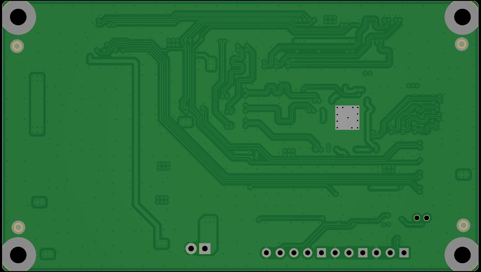
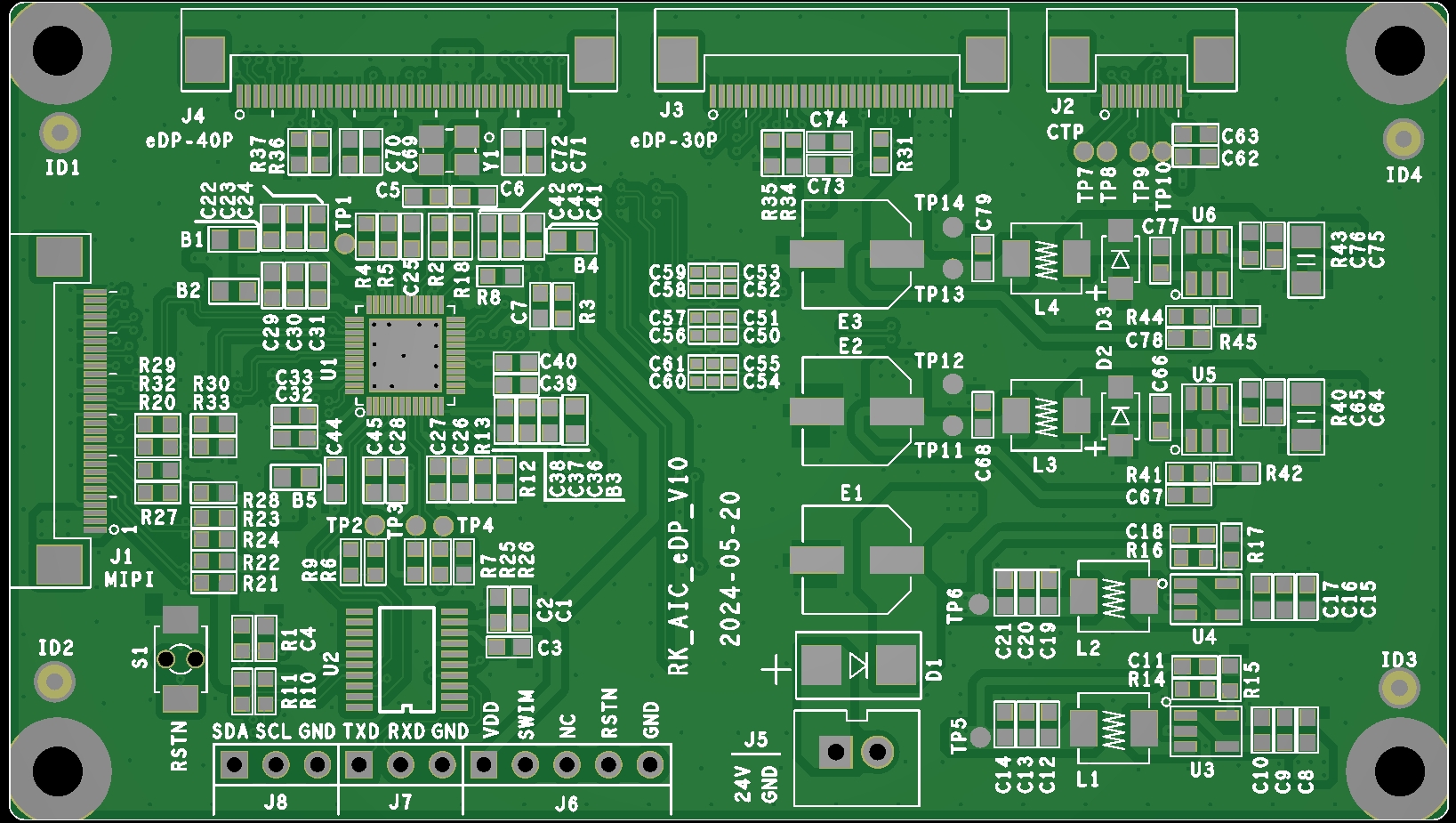

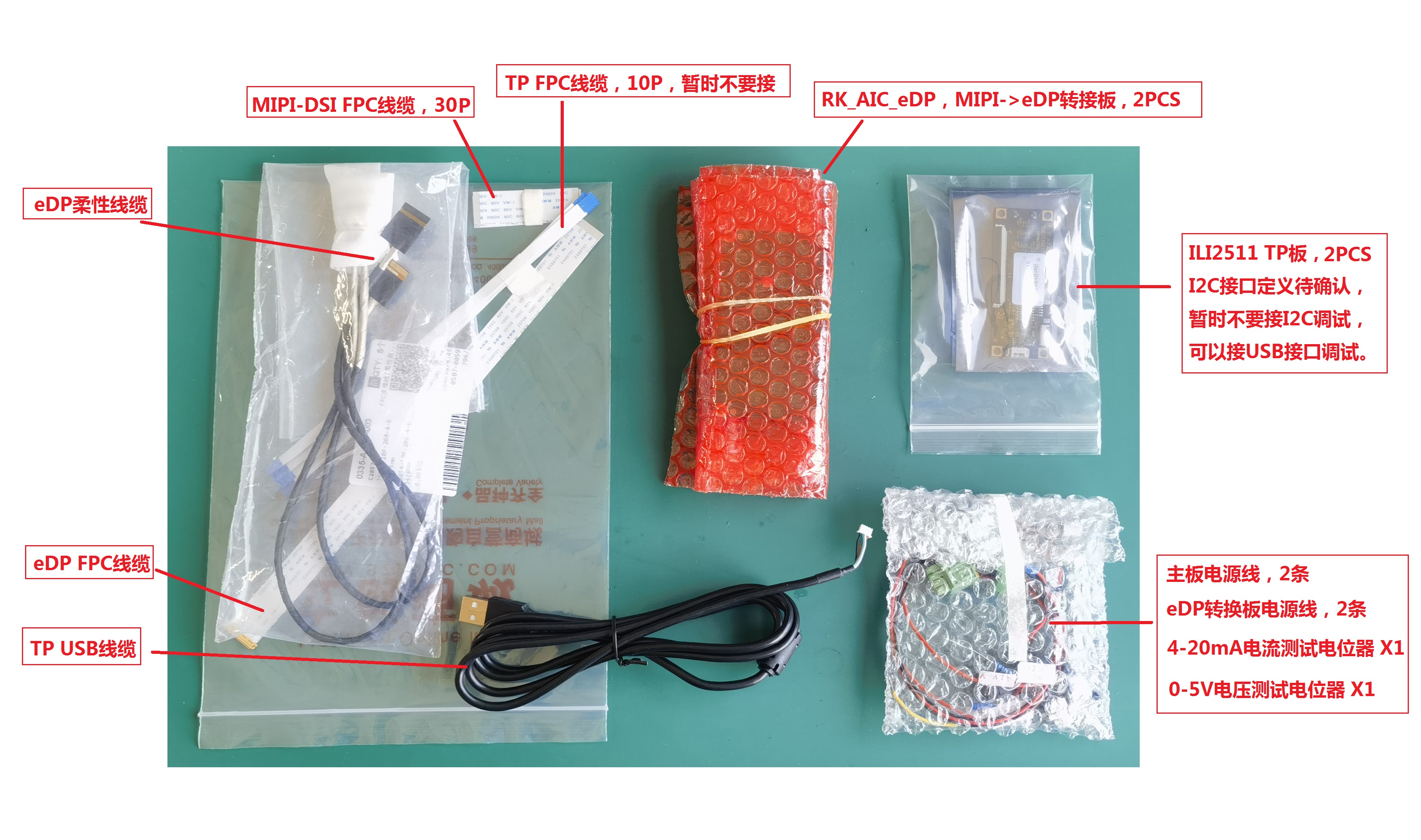
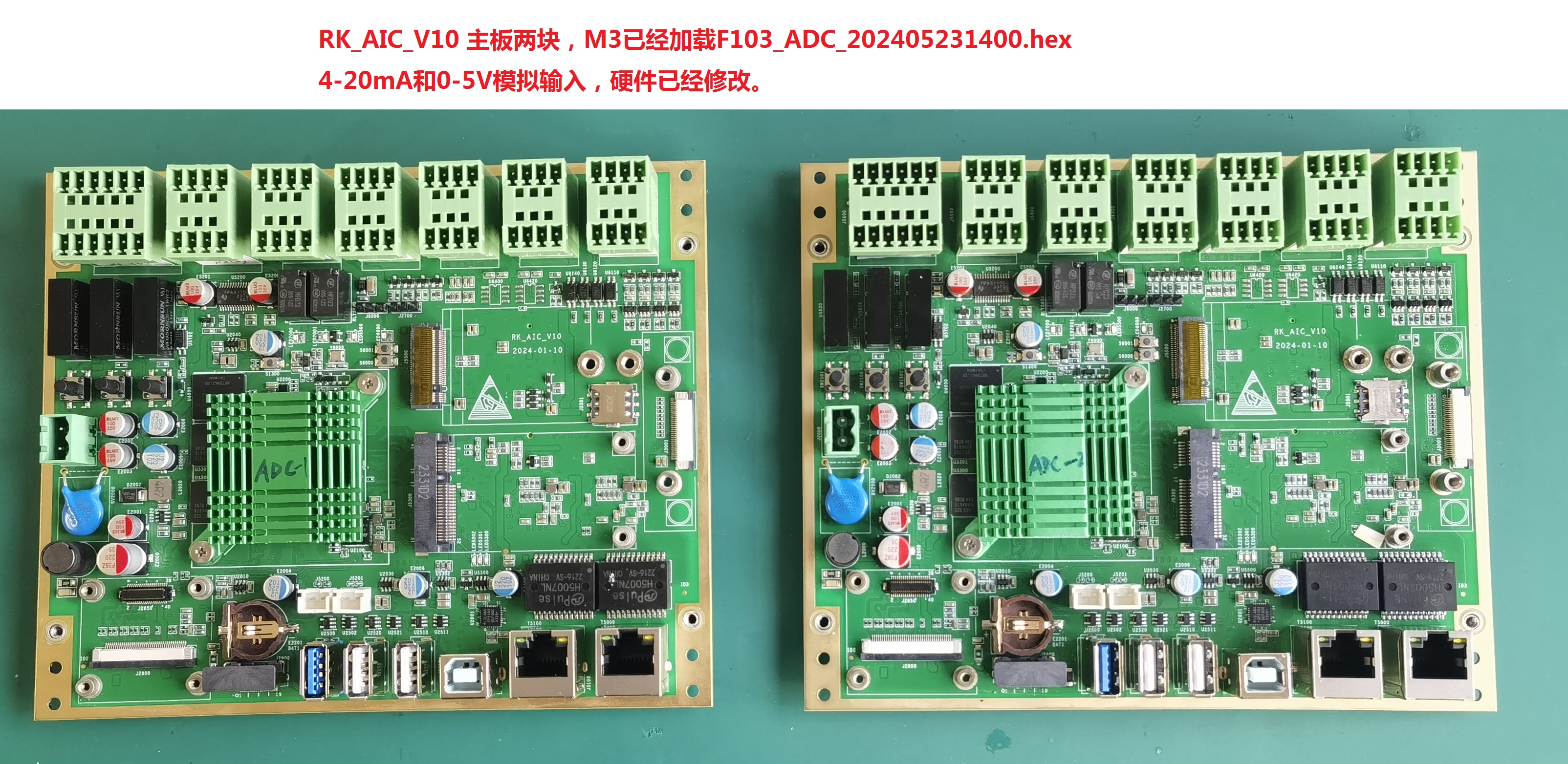
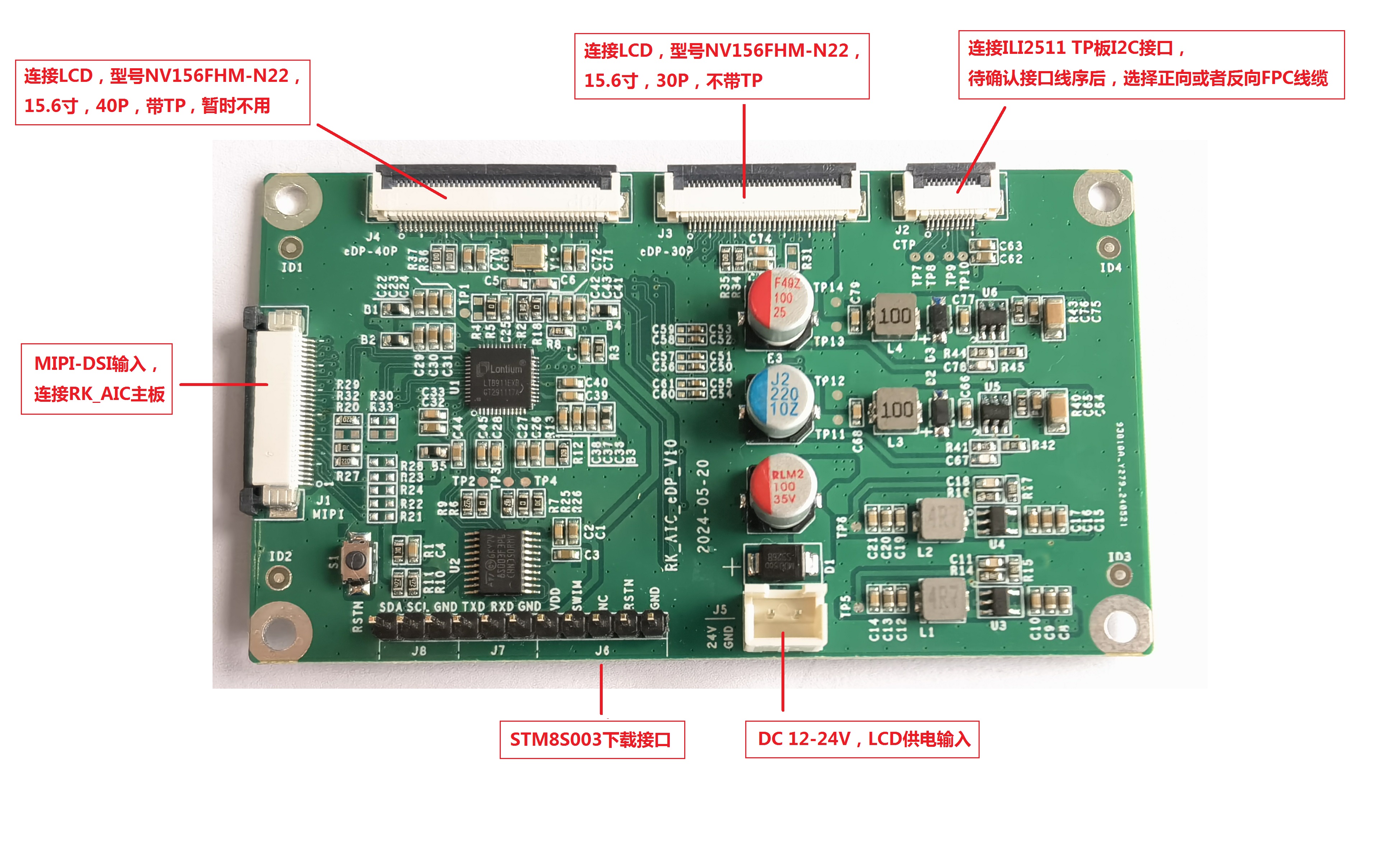
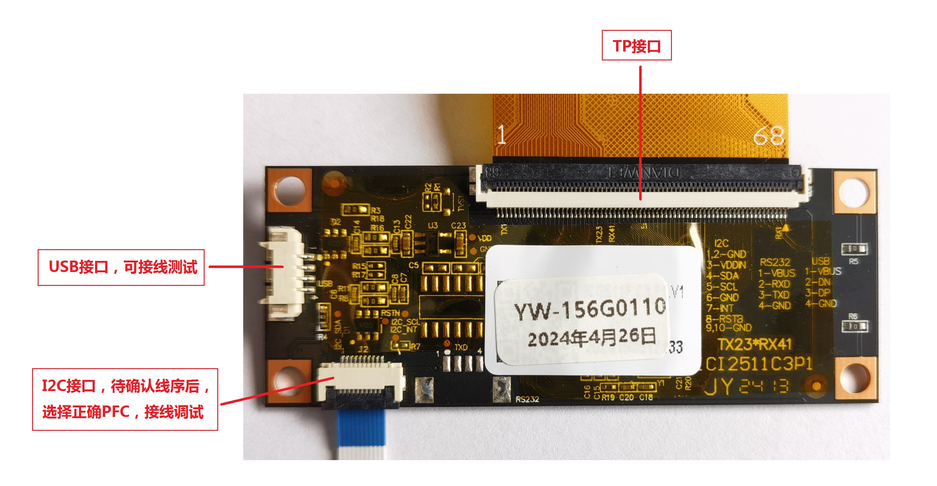
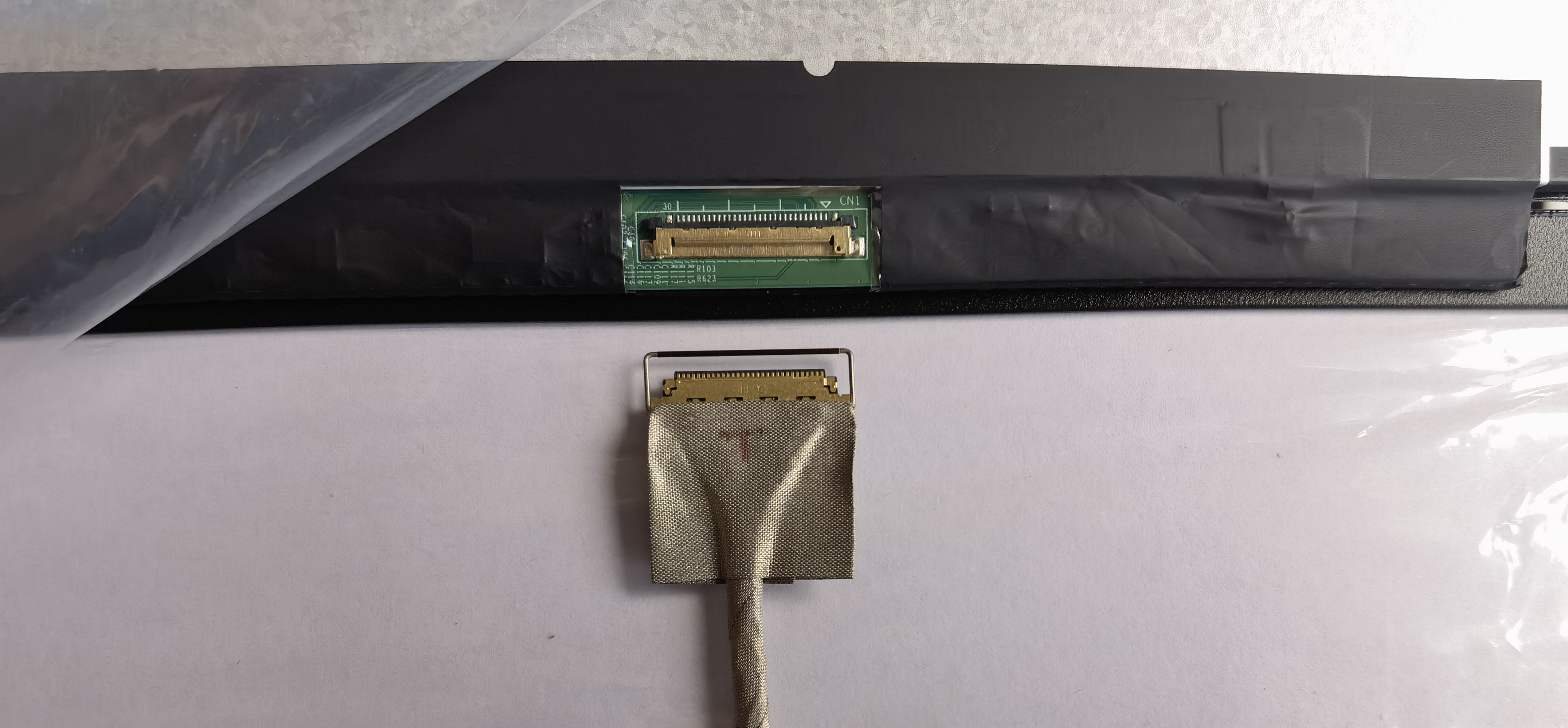
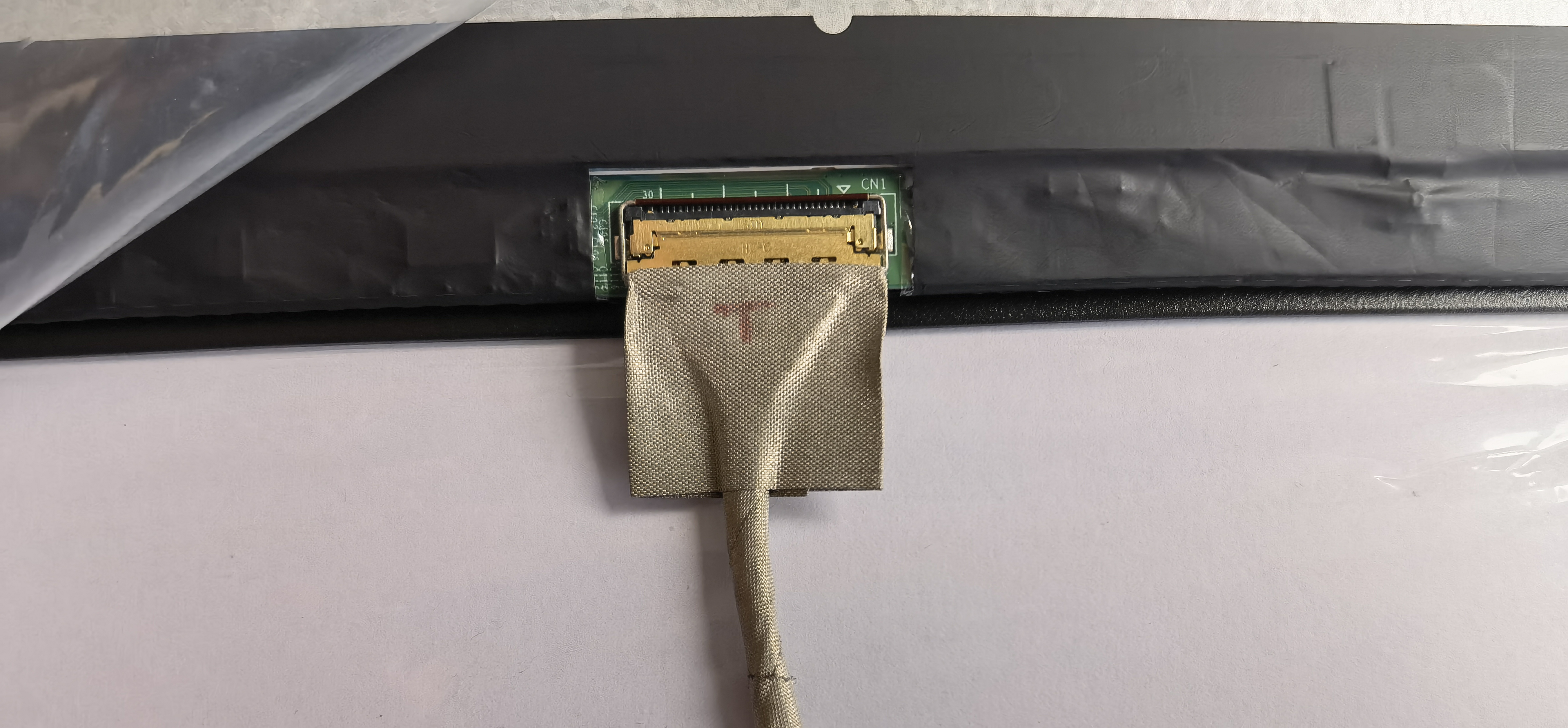
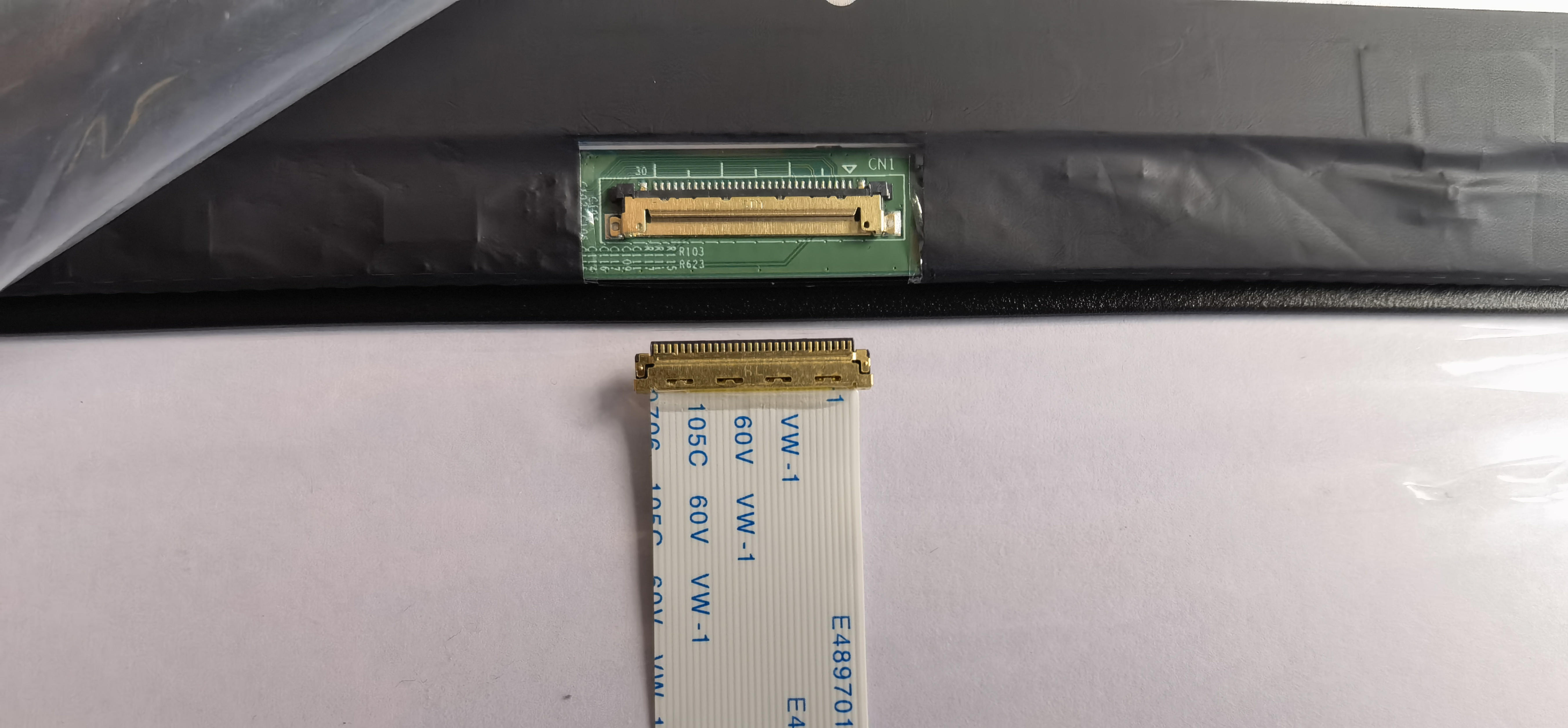
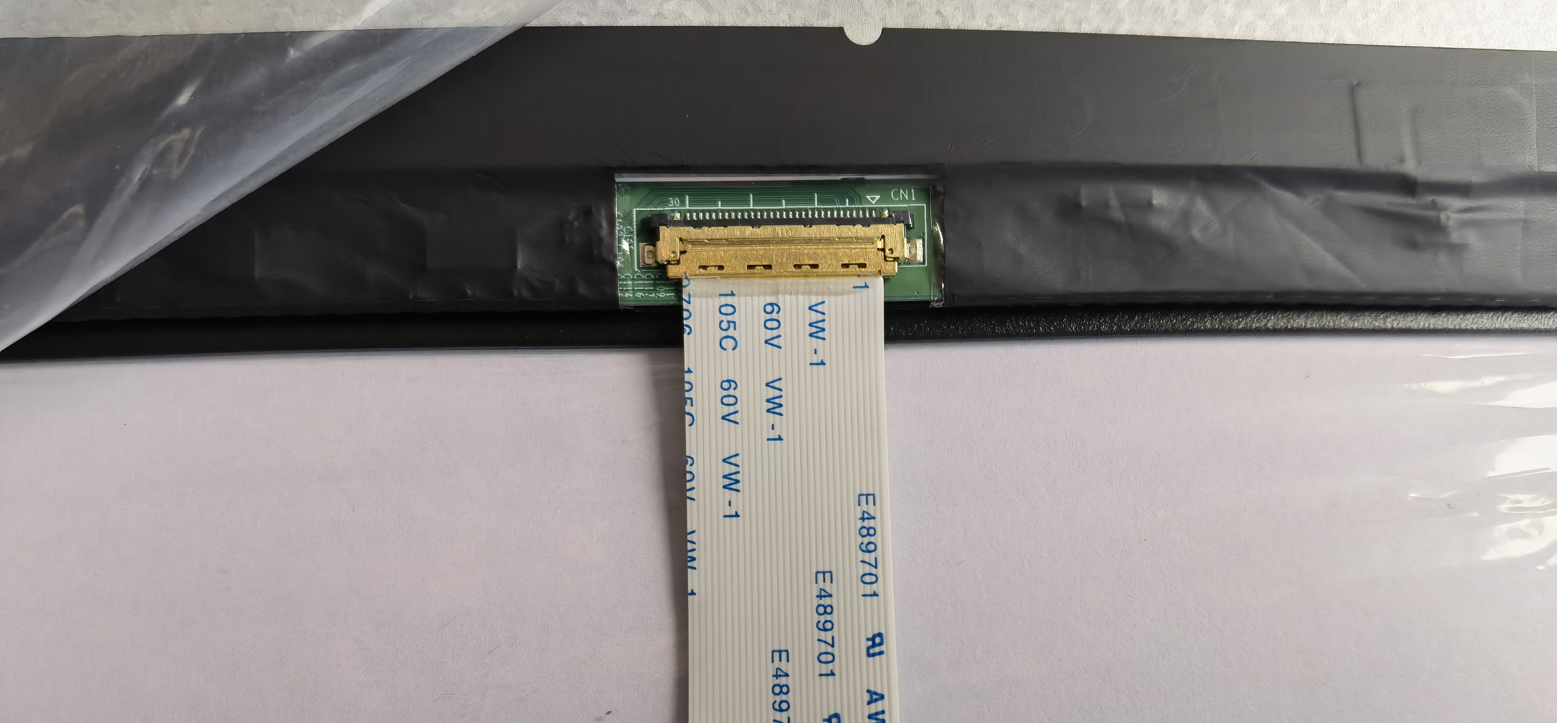
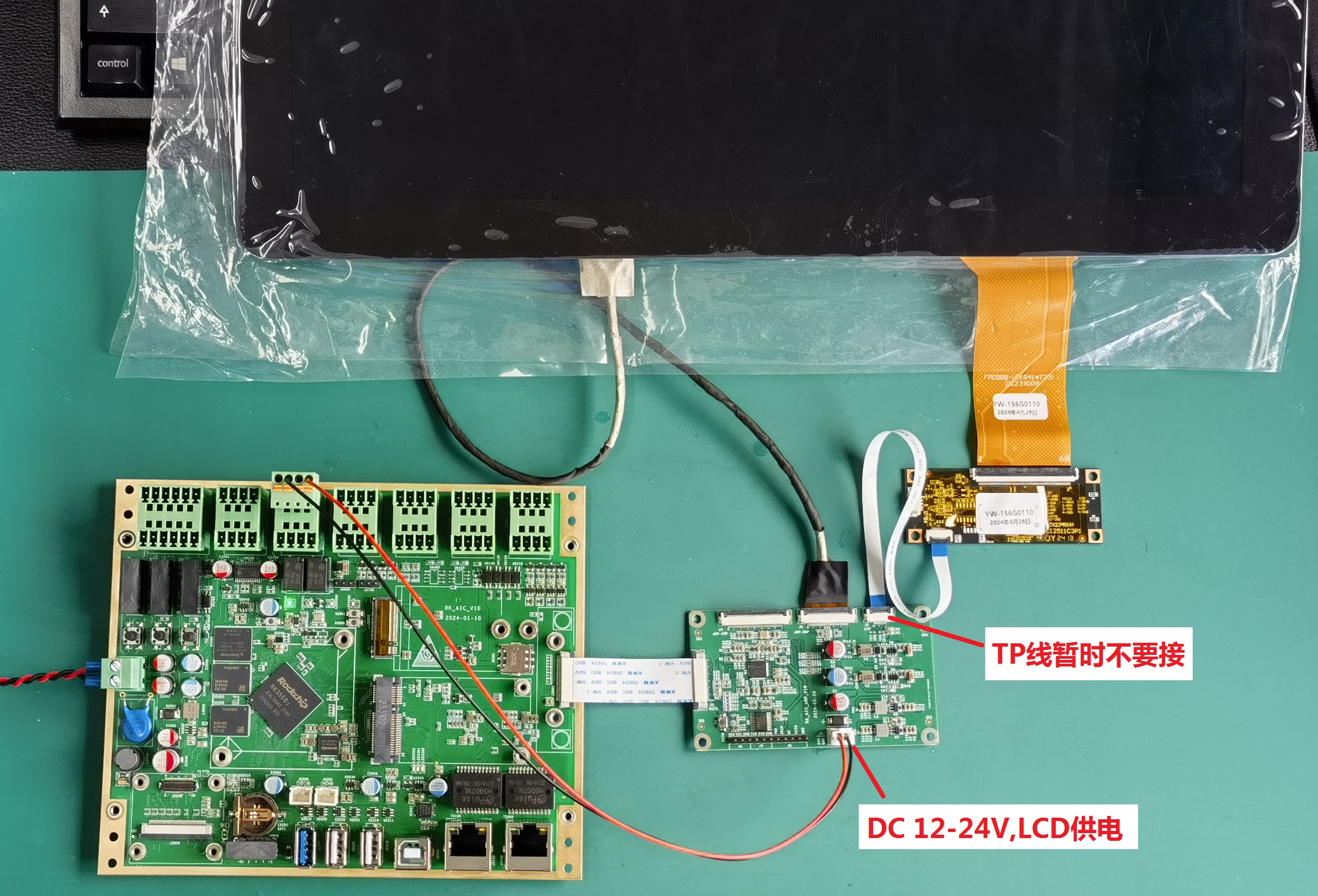
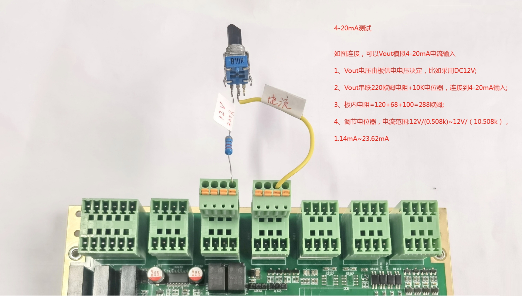
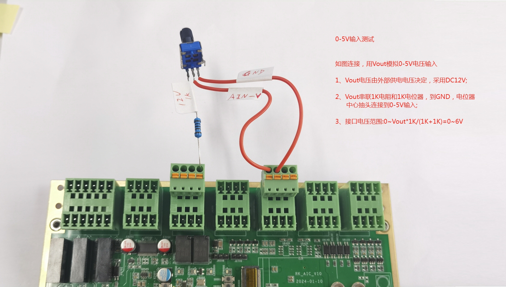